|
|
|
|
OPC 10000-15 |
|
|
OPC Unified Architecture Part 15: Safety
Release 1.05.04 2024-10-15
|

|
|
|
|
OPC 10000-15 |
|
|
OPC Unified Architecture Part 15: Safety
Release 1.05.04 2024-10-15
|
|
Standard Type: |
Industry Standard Specification |
Comments: |
|||
|
|
|
|
|
||
|
Document |
OPC 10000-15 |
|
|
||
|
Title: |
OPC Unified
Architecture |
Date: |
2024-10-15 |
||
|
|
|
|
|
||
|
Version: |
Release 1.05.04 |
Software: |
MS-Word |
||
|
Editors: |
|
Source: |
OPC 10000-15 - UA Specification Part 15 - Safety 1.05.04.docx |
||
|
|
|
|
|
||
|
Owner: |
OPC Foundation and PROFIBUS Nutzerorganisation e.V. |
Status: |
|
||
|
|
|
|
|
||
CONTENTS
3 Terms, definitions, symbols, abbreviated terms and conventions
3.1.1 Common terms and definitions
3.1.2 Additional terms and definitions
3.2 Symbols and abbreviated terms
3.2.1 Abbreviated terms from IEC 61784-3
3.2.2 Additional symbols and abbreviated terms
3.3.2 Conventions for requirements numbering
3.3.3 Conventions in state machines
5.1 External documents providing specifications for the profile
5.2 Safety functional requirements
5.4 Safety communication layer structure
5.5 Requirements for CRC calculation
6 Safety communication layer services
6.2.2 Object and ObjectType Definitions
6.2.5 DataTypes and length of SafetyData
6.2.6 Connection establishment
6.3.2 OPC UA Platform interface (OPC UA PI)
6.3.3 SafetyProvider interfaces
6.3.4 SafetyConsumer interfaces
6.3.5 Cyclic and acyclic safety communication
6.3.6 Principle for “application variables with qualifier”
6.4.2 Diagnostics messages of the SafetyConsumer
6.4.3 Method ReadSafetyDiagnostics of the SafetyProvider
7 Safety communication layer protocol
7.2 SafetyProvider and SafetyConsumer
8 Safety communication layer management
8.2 Safety function response time part of communication
9 System requirements (SafetyProvider and SafetyConsumer)
9.1 Constraints on the SPDU parameters
9.1.1 SafetyBaseID and SafetyProviderID
9.2 Initialization of the MNR in the SafetyConsumer
9.3 Constraints on the calculation of system characteristics
9.3.1 Probabilistic considerations (informative)
9.3.2 Safety related assumptions (informative)
9.4 PFH and PFD values of a logical safety communication link
10.3 Index of requirements (informative)
11 Profiles and Conformance Units
12.2 Handling of OPC UA namespaces
Annex A (normative) Safety Namespace and mappings
Annex B (informative) Additional information.
B.1 CRC calculation using tables, for the polynomial 0xF4ACFB13
B.2.1 Unidirectional communication
B.2.2 Bidirectional communication
B.3 Use cases for Operator Acknowledgment
B.3.2 Use case 1: unidirectional communication and OA on the SafetyConsumer side
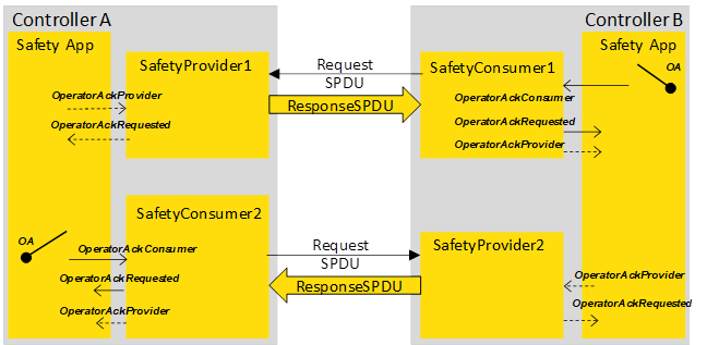
B.3.3 Use case 2: bidirectional communication and dual OA
B.3.4 Use case 3: bidirectional communication and single, one-sided OA
B.3.5 Use case 4: bidirectional communication and single, two-sided OA
Annex C (informative) Information for assessment
Figure 1 (informative) – Relationships of OPC UA Safety with other standards.................. xi
Figure 5 – Safety multicast with three recipients using IEC 62541 PubSub...................... 21
Figure 6 – Safety parameters for the SafetyProvider and the SafetyConsumer.................. 22
Figure 13 (informative) – Sequence diagram for requests and responses (Client/Server)..... 47
Figure 14 (informative) – Sequence diagram for requests and responses (PubSub)........... 48
Figure 17 – Simplified representation of the state diagram for the SafetyProvider.............. 50
Figure 22 (informative) – Example for the calculation of SPDU_ID_1, SPDU_ID_2 and SPDU_ID_3 65
Figure 23 – Calculation of the CRC (on little-endian machines, CRC32_Backward)............ 68
Figure 24 – Calculation of the CRC (on big-endian machines, CRC32_Forward)............... 69
Figure 27 – Counter example: data lengths not supported by OPC Safety....................... 75
Figure B.5 – Two-sided OA in bidirectional safety communication.................................. 88
Figure B.6 – One sided OA in bidirectional safety communication.................................. 88
Table 2 – Deployed safety measures to detect communication errors............................... 9
Table 8 – ReadSafetyData Method AddressSpace definition........................................ 18
Table 9 – ReadSafetyDiagnostics Method arguments................................................. 19
Table 10 – ReadSafetyDiagnostics Method AddressSpace definition.............................. 20
Table 13 – SafetyConsumerParametersType definition............................................... 23
Table 22 – NonSafetyDataPlaceholderDataType structure........................................... 27
Table 38 – Examples for cryptographically strong random number generators.................. 72
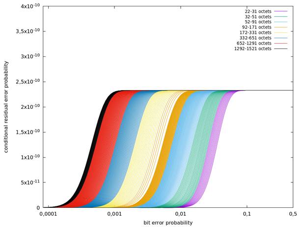
Table 39 – The total residual error rate for the safety communication channel.................. 76
Table 42 – NamespaceMetadata Object for this document........................................... 81
Table B.1 – The CRC32 lookup table for 32-bit CRC signature calculations..................... 84
OPC Foundation
____________
UNIFIED ARCHITECTURE
Part 15: Safety
This specification is the specification for developers of OPC UA applications. The specification is a result of an analysis and design process to develop a standard interface to facilitate the development of applications by multiple vendors that shall inter-operate seamlessly together.
Copyright © 2006-2024, OPC Foundation, Inc.
ACKNOWLEDGEMENT
This specification has its origin in a joint working group between the OPC Foundation and the PROFIBUS Nutzerorganisation e.V. (PNO) which was established in November 2017. The experts of this joint working group initially elaborated a safety concept for controller-to-controller communication using an approach according to IEC 61784-3 “Functional safety fieldbuses” based on the OPC UA Client/Server communication model. The launch of the Field Level Communication Initiative in November 2018 has resulted in an extension of the safety concept to also support controller-to-device communication and the Pub/Sub communication including transport via Ethernet and Ethernet TSN.
AGREEMENT OF USE
COPYRIGHT RESTRICTIONS
Any unauthorized use of this specification may violate copyright laws, trademark laws, and communications regulations and statutes. This document contains information which is protected by copyright. All Rights Reserved. No part of this work covered by copyright herein may be reproduced or used in any form or by any means--graphic, electronic, or mechanical, including photocopying, recording, taping, or information storage and retrieval systems--without permission of the copyright owner.
OPC Foundation members and non-members are prohibited from copying and redistributing this specification. All copies must be obtained on an individual basis, directly from the OPC Foundation Web site http://www.opcfoundation.org..
PATENTS
The attention of adopters is directed to the possibility that compliance with or adoption of OPC specifications may require use of an invention covered by patent rights. OPC shall not be responsible for identifying patents for which a license may be required by any OPC specification, or for conducting legal inquiries into the legal validity or scope of those patents that are brought to its attention. OPC specifications are prospective and advisory only. Prospective users are responsible for protecting themselves against liability for infringement of patents.
WARRANTY AND LIABILITY DISCLAIMERS
WHILE THIS PUBLICATION IS BELIEVED TO BE ACCURATE, IT IS PROVIDED “AS IS” AND MAY CONTAIN ERRORS OR MISPRINTS. THE OPC FOUDATION MAKES NO WARRANTY OF ANY KIND, EXPRESSED OR IMPLIED, WITH REGARD TO THIS PUBLICATION, INCLUDING BUT NOT LIMITED TO ANY WARRANTY OF TITLE OR OWNERSHIP, IMPLIED WARRANTY OF MERCHANTABILITY OR WARRANTY OF FITNESS FOR A PARTICULAR PURPOSE OR USE. IN NO EVENT SHALL THE OPC FOUNDATION BE LIABLE FOR ERRORS CONTAINED HEREIN OR FOR DIRECT, INDIRECT, INCIDENTAL, SPECIAL, CONSEQUENTIAL, RELIANCE OR COVER DAMAGES, INCLUDING LOSS OF PROFITS, REVENUE, DATA OR USE, INCURRED BY ANY USER OR ANY THIRD PARTY IN CONNECTION WITH THE FURNISHING, PERFORMANCE, OR USE OF THIS MATERIAL, EVEN IF ADVISED OF THE POSSIBILITY OF SUCH DAMAGES.
The entire risk as to the quality and performance of software developed using this specification is borne by you.
RESTRICTED RIGHTS LEGEND
This Specification is provided with Restricted Rights. Use, duplication or disclosure by the U.S. government is subject to restrictions as set forth in (a) this Agreement pursuant to DFARs 227.7202-3(a); (b) subparagraph (c)(1)(i) of the Rights in Technical Data and Computer Software clause at DFARs 252.227-7013; or (c) the Commercial Computer Software Restricted Rights clause at FAR 52.227-19 subdivision (c)(1) and (2), as applicable. Contractor / manufacturer are the OPC Foundation, 16101 N. 82nd Street, Suite 3B, Scottsdale, AZ, 85260-1830.
COMPLIANCE
The OPC Foundation shall at all times be the sole entity that may authorize developers, suppliers and sellers of hardware and software to use certification marks, trademarks or other special designations to indicate compliance with these materials. Products developed using this specification may claim compliance or conformance with this specification if and only if the software satisfactorily meets the certification requirements set by the OPC Foundation. Products that do not meet these requirements may claim only that the product was based on this specification and must not claim compliance or conformance with this specification.
Trademarks
Most computer and software brand names have trademarks or registered trademarks. The individual trademarks have not been listed here.
GENERAL PROVISIONS
Should any provision of this Agreement be held to be void, invalid, unenforceable or illegal by a court, the validity and enforceability of the other provisions shall not be affected thereby.
This Agreement shall be governed by and construed under the laws of the State of Minnesota, excluding its choice or law rules.
This Agreement embodies the entire understanding between the parties with respect to, and supersedes any prior understanding or agreement (oral or written) relating to, this specification.
ISSUE REPORTING
The OPC Foundation strives to maintain the highest quality standards for its published specifications; hence they undergo constant review and refinement. Readers are encouraged to report any issues and view any existing errata here: http://www.opcfoundation.org/errata.
Revision 1.05.04 Highlights
The following table includes the issues resolved with this revision.
|
Mantis ID |
Scope |
Summary |
Resolution |
|
Errata |
Missing Documentation About Duration of Demand |
Added new Subclause 7.2.2.3 “Duration of demand“. Removed obsolete item 7 from Table 40. |
|
|
Clarification |
Clarify Byte Order of SafetyBaseID in Calculation of the SPDU_ID |
Added new Subclause 7.2.3.3 “Example for the calculation of SPDU_ID_1, SPDU_ID_2 and SPDU_ID_3 (informative)“. Adapted Figure 21 wording to IEC “octet(s)”. |
|
|
Clarification |
Merge Changes from IEC Standardization Document Stream |
Minor technical rewordings and editorial changes were backported from the IEC CD stage. |
|
|
Errata |
Misleading Wording in Requirement RQ7.15 About Order of Constructing ResponseSPDU |
In RQ7.15, replaced “after that“ with “in addition”. |
|
|
Clarification |
Requirement 5.6 "Ignore All-Zero SPDUs" Needs Detailing |
Detailing of requirement RQ5.6 regarding actual Client/Server behavior. |
|
|
Clarification |
Section about "Duration of Demand" misses explanations about timeout-based and bidirectional approaches |
Add respective explanations to 7.2.2.3. |
|
|
Errata |
Nodeset changes concerning missing HasComponent relations |
Added HasComponent relations to SafetyPDUs Objects’ RequestSPDU and ResponseSPDU. |
|
|
Errata |
Editorial Issues in 1.05.04 RC |
Removed unexplained bold red highlighting of method arguments OutSafetyData and OutNonSafetyData in signature descriptions for methods ReadSafetyData and ReadSafetyDiagnostics and added explanations that these are abstract types that have to be concretized for specific applications. Table 23: added missing blank after "document" in entry for SafetyConsumerID. Figure 9: corrected misalignment of SafetyConsumer in F-PLC. Table 24 – SPI of the SafetyProvider: adapted to consistent usage of range "0x0 – 0xFFFFFFFF" (vs. "0 – 0xFFFFFFFF"). Table 25 – SAPI of the SafetyConsumer: uniformly formatted terms in first column in italics. Table 26 – SPI of the SafetyConsumer: Harmonized the wording explaining the SafetyProviderIDConfigured parameter (using the wording from the SafetyBaseIDConfigured parameter). 6.3.4.3 - Motivation for SAPI Operator Acknowledge (OperatorAckConsumer): added link to 6.3.4.5 - Motivation for SPI SafetyOperatorAckNecessary to last paragraph. Figure 16: noted availability of demand value "C" at occurrence of second new MNR. |
OPC UA Safety extends OPC UA to fulfill the requirements of functional safety as defined in the IEC 61508 series and IEC 61784-3 series of standards.
Figure 1 shows the relationship between this document and the relevant safety and OPC UA standards in an industrial environment. An arrow from Document A to Document B means “Document A is referenced in Document B”. This reference can be either normative or informative. Not all of these standards are applicable or required for a given product.
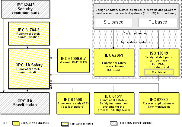
Figure 1 (informative) – Relationships of OPC UA Safety with other standards
Implementing this document allows for detecting all types of communication errors encountered in the lower network layers. In case an error is detected, this information is shared with the safety applications in the User Layer which can then act in an appropriate way, e.g. by switching to a safe state.
The document describes the behaviour of the individual endpoints for safe communication, as well as the OPC UA Information Model which is used to access these endpoints.
This document is application-independent and does not pose requirements on the structure and length of the application data. Application-specific requirements are expected to be described in appropriate companion specifications.
This document can be used for applications requiring functional safety up to the safety integrity level (SIL) 4.
OPC Unified Architecture Specification
Part 15: Safety
This document describes a safety communication layer (services and a protocol) for the exchange of SafetyData using OPC UA mechanisms. It identifies the principles for functional safety communications defined in IEC 61784‑3 that are relevant for this safety communication layer. This safety communication layer is intended for implementation in safety devices only.
NOTE 1 This document targets controller-to-controller communication. However, easy expandability to other use-cases (e.g. OPC UA field level communication) has already been considered in the design of this document.
NOTE 2 This document does not cover electrical safety and intrinsic safety aspects. Electrical safety relates to hazards such as electrical shock. Intrinsic safety relates to hazards associated with potentially explosive atmospheres.
This document defines mechanisms for the transmission of safety-relevant messages among participants within a network using OPC UA technology in accordance with the requirements of the IEC 61508 series and IEC 61784-3 for functional safety. These mechanisms can be used in various industrial applications such as process control, manufacturing, automation, and machinery.
This document provides guidelines for both developers and assessors of compliant devices and systems.
NOTE 3 The resulting SIL claim of a system depends on the implementation of this document within the system – implementation of this document in a standard device is not sufficient to qualify it as a safety device.
The following documents are referred to in the text in such a way that some or all of their content constitutes requirements of this document. For dated references, only the edition cited applies. For undated references, the latest edition of the referenced document (including any amendments) applies.
IEC 61508 (all parts), Functional safety of electrical/electronic/programmable electronic safety-related systems
IEC 61784‑3:2021, Industrial communication networks – Profiles – Part 3: Functional safety fieldbuses – General rules and profile definitions
IEC 62443 (all parts), Industrial communication networks – Network and system security
OPC 10000-1, OPC Unified Architecture – Part 1: Overview and Concepts
OPC 10000-3, OPC Unified Architecture – Part 3: Address Space Model
OPC 10000-4, OPC Unified Architecture – Part 4: Services
OPC 10000-5, OPC Unified Architecture – Part 5: Information Model
OPC 10000-6, OPC Unified Architecture – Part 6: Mappings
OPC 10000-14, OPC Unified Architecture – Part 14: PubSub
ISO/IEC 9834-8:2014, Information technology – Procedures for the operation of object identifier registration authorities – Part 8: Generation of universally unique identifiers (UUIDs) and their use in object identifiers
For the purposes of this document, the terms and definitions given in OPC 10000-1, OPC 10000-3, OPC 10000‑4, OPC 10000-6 and the following apply.
ISO and IEC maintain terminology databases for use in standardization at the following addresses:
· IEC Electropedia: available at https://www.electropedia.org/
· ISO Online browsing platform: available at https://www.iso.org/obp
NOTE This document uses concepts of OPC UA information modeling to describe the concepts in this document.
3.1.1.1
Cyclic Redundancy Check
CRC
<value> redundant data derived from, and stored or transmitted together with, a block of data in order to detect data corruption
<method> procedure used to calculate the redundant data
Note 1 to entry: Terms “CRC code” and “CRC signature”, and labels such as CRC1, CRC2, may also be used in this document to refer to the redundant data.
[SOURCE: IEC 61784-3:2021, 3.10]
3.1.1.2
error
discrepancy between a computed, observed or measured value or condition and the true, specified or theoretically correct value or condition
Note 1 to entry: Errors may be due to design mistakes within hardware/software and/or corrupted information due to electromagnetic interference and/or other effects.
Note 2 to entry: Errors do not necessarily result in a failure or a fault.
[SOURCE: IEC 60050-192:2024, 192-03-02, modified – notes added]
3.1.1.3
failure
termination of the ability of a functional unit to perform a required function or operation of a functional unit in any way other than as required
Note 1 to entry: Failure may be due to an error (for example, problem with hardware/software design or message disruption).
[SOURCE: IEC 61508‑4:2010, 3.6.4, modified – notes and figures deleted, new note to entry added]
3.1.1.4
fault
abnormal condition that may cause a reduction in, or loss of, the capability of a functional unit to perform a required function
Note 1 to entry: IEV 191‑05‑01 defines “fault” as a state characterized by the inability to perform a required function, excluding the inability during preventive maintenance or other planned actions, or due to lack of external resources.
[SOURCE: IEC 61508‑4:2010, 3.6.1, modified – figure reference deleted]
message
<information theory and communication theory> ordered sequence of characters (usually octets) intended to convey information
[SOURCE: ISO/IEC 2382:2015, 2123031, modified – insertion of "(usually octets)", deletion of notes and source]
3.1.1.6
performance level
PL
discrete level used to specify the ability of safety-related parts of control systems to perform a safety function under foreseeable conditions
[SOURCE: ISO 13849‑1:2023, 3.1.5]
3.1.1.7
residual error probability
probability of an error undetected by the SCL safety measures
[SOURCE: IEC 61784-3:2021 3.1]
3.1.1.8
residual error rate
statistical rate at which the SCL safety measures fail to detect errors
[SOURCE: IEC 61784-3:2021, 3.1.35]
3.1.1.9
safety communication layer
SCL
communication layer above the OPC UA communication stack that includes all necessary additional measures to ensure safe transmission of data in accordance with the requirements of IEC 61508
Note 1 to entry: The SCL provides several services, the most important ones being the SafetyProvider and the SafetyConsumer.
[SOURCE: IEC 61784-3:2021, 3.1.39 modified – “FAL” replaced by “OPC UA communication stack”, not to entry added]
safety function response time
worst case elapsed time following an actuation of a safety sensor connected to a fieldbus, until the corresponding safe state of its safety actuator(s) is achieved in the presence of errors or failures in the safety function
Note 1 to entry: This concept is introduced in IEC 61784‑3:2021, 5.2.4 and is addressed by the functional safety communication profiles defined in the IEC 61784-3 series of documents.
[SOURCE: IEC 61784-3:2021, 3.1.44]
3.1.1.11
safety integrity level
SIL
discrete level (one out of a possible four), corresponding to a range of safety integrity values, where safety integrity level 4 has the highest level of safety integrity and safety integrity level1 has the lowest
Note 1 to entry: The target failure measures (see IEC 61508‑4:2010, 3.5.17) for the four safety integrity levels are specified in Table 2 and Table 3 of IEC 61508‑1:2010.
Note 2 to entry: Safety integrity levels are used for specifying the safety integrity requirements of the safety functions to be allocated to the E/E/PE safety-related systems.
Note 3 to entry: A safety integrity level (SIL) is not a property of a system, subsystem, element or component. The correct interpretation of the phrase “SIL n safety-related system” (where n is 1, 2, 3 or 4) is that the system is potentially capable of supporting safety functions with a safety integrity level up to n.
[SOURCE: IEC 61508‑4:2010, 3.5.8]
3.1.1.12
safety measure
measure to control possible communication errors that is designed and implemented in compliance with the requirements of IEC 61508
Note 1 to entry: In practice, several safety measures are combined to achieve the required safety integrity level.
Note 2 to entry: Communication errors and related safety measures are detailed in IEC 61784‑3:2021, 5.3 and 5.4.
[SOURCE: IEC 61784-3:2021, 3.1.46]
safety PDU
SPDU
PDU transferred through the safety communication channel
Note 1 to entry: The SPDU may include more than one copy of the SafetyData using differing coding structures and hash functions together with explicit parts of additional protections such as a key, a sequence count, or a time stamp mechanism.
Note 2 to entry: Redundant SCLs may provide two different versions of the SPDU for insertion into separate fields of the OPC UA frame.
[SOURCE: IEC 61784-3:2021, 3.1.47]
3.1.2.1
fail-safe
ability of a system that, by adequate technical or organizational measures, prevents from hazards either deterministically or by reducing the risk to a tolerable measure
Note 1 to entry: Equivalent to functional safety.
3.1.2.2
fail-safe substitute values
FSV
values which are issued or delivered instead of process values when the safety function is set to a fail-safe state
Note 1 to entry: In this document, the fail-safe substitute values (FSV) are always set to binary “0”.
3.1.2.3
flag
one-bit value used to indicate a certain status or control information
3.1.2.4
Globally Unique Identifier
GUID
128-bit number used to identify information in computer systems
Note 1 to entry: The term universally unique identifier (UUID) is also used.
Note 2 to entry: In this document, UUID version 4 is used.
3.1.2.5
MonitoringNumber
MNR
means used to ensure the correct order among transmitted safety PDUs and to monitor the communication delay
Note 1 to entry: Instance of sequence number as described in IEC 61784‑3.
Note 2 to entry: The MNR starts at a random value and is incremented with each request. It rolls over to a minimum threshold value that is not zero.
Note 3 to entry: The transmitted MNR is protected by the transmitted CRC signature of the ResponseSPDU.
3.1.2.6
Non-safety-
predicate meaning that the respective object is a “standard” object and has not been designed and implemented to fulfil any requirements with respect to functional safety
3.1.2.7
OPC UA Mapper
non-safety-related part of the implementation of this document which maps the SPDU to the actual OPC UA services
Note 1 to entry: Depending on which services of OPC UA are being used (e.g. Client/Server or PubSub), different mappers can be specified.
3.1.2.8
process values
PV
input and output data (in a safety PDU) that are required to control an automated process
3.1.2.9
qualifier
attribute (bit or Boolean), indicating whether the corresponding value is valid or not (e.g. being a fail-safe substitute value)
3.1.2.10
SafetyAutomationComponent
SafetyAC
communication partner in a unidirectional safety link
Note 1 to entry: A SafetyAutomationComponent can be a SafetyProvider (data source), a SafetyConsumer (data sink), or both.
3.1.2.11
SafetyConsumer
entity (usually software) that implements the data sink of a unidirectional safety link
SafetyData
application data transmitted across a safety network using a safety protocol
Note 1 to entry; The safety communication layer does not ensure the safety of the data itself, but only that the data is transmitted safely.
3.1.2.13
SafetyProvider
entity (usually software) that implements the data source of a unidirectional safety link
SafetyBaseID
randomly generated authenticity ID which is used to safely authenticate SafetyProviders having the same SafetyProviderID
Note 1 to entry: Together with the SafetyProviderID, it is an instance of connection authentication as described in IEC 61784‑3.
SafetyProviderID
user-assigned, locally unique identifier which is used to safely authenticate SafetyProviders within a certain area
Note 1 to entry: Together with the SafetyBaseID, it is an instance of connection authentication as described in IEC 61784‑3.
Note 1 to entry: All SafetyProviders within an area such defined may share an identical SafetyBaseID.
3.1.2.16
standard transmission system
part of the transmission system (implemented in hardware and software) that is not implemented according to any safety standards
Note 1 to entry: This document is using the services of the standard transmission system to transmit prebuilt safety packets.
For the purposes of this document, the following symbols and abbreviated terms apply.
|
Cyclic Redundancy Check |
|
|
|
PDU |
Protocol Data Unit |
[ISO/IEC 7498‑1] |
|
PL |
Performance Level |
[ISO 13849‑1] |
|
PLC |
Programmable Logic Controller |
|
|
SCL |
Safety Communication Layer |
|
|
SIL |
safety integrity level |
[IEC 61508‑4] |
|
SPDU |
Safety PDU, Safety Protocol Data Unit |
|
|
Fail-safe substitute Values |
|
|
|
HMI |
Human-machine interface |
|
|
ID |
Identifier |
|
|
LSB |
Least significant bit |
|
|
MNR |
MonitoringNumber |
|
|
MSB |
Most significant bit |
|
|
OA |
Operator Acknowledgment |
|
|
OPC UA PI |
OPC UA Platform Interface |
|
|
PI |
Platform Interface |
|
|
PV |
Process Values |
|
|
SAPI |
Safety Application Program Interface |
|
|
SFRT |
Safety Function Response Time |
|
|
SPI |
Safety Parameter Interface |
|
|
STrailer |
Safety Trailer |
|
|
TRA |
threat and risk analysis |
|
|
p |
Bit error probability |
|
|
Pre,cond |
Conditional residual error probability |
|
Italics are used to denote a defined term or definition that appears in 3.1.
Italics are also used to denote the name of a service input or output parameter or the name of a structure or element of a structure that are usually defined in tables.
The italicized terms and names are also often written in camel-case (the practice of writing compound words or phrases in which the elements are joined without spaces, with each element's initial letter capitalized within the compound). For example, the defined term is AddressSpace instead of Address Space. This makes it easier to understand that there is a single definition for AddressSpace, not separate definitions for Address and Space. Terms or names where two capital letters of abbreviations are in sequence or for separation to a suffix are written with underscores in between.
The abbreviation “F” is an indication for safety- related items, technologies, systems, and units (fail-safe, functional safe).
The default data that are used in case of unit failures or errors, are called fail-safe substitute values (FSV) and are set to binary “0”.
Reserved bits (“res”) are set to “0” and ignored by the receiver to avoid problems with future versions of this document.
The notation 0x… represents a hexadecimal value.
Requirements in this document are designated as [RQx.yz], where x denotes the chapter number, y is a counter and z is an optional character to link closely related requirements. The following are examples of valid requirements designations: [RQ8.15] (requirement 15 in chapter 8); [RQ47.11a], [RQ47.11b] (requirements 11a and 11b in chapter 47, which are closely related).
The initial numbering of requirements was chosen such that counters within each chapter are in ascending order. However, the addition of further requirements leads to deviations from this rule since existing requirements shall keep their initial designation.
For an informative index of all the requirements in this document, see 10.3.
See Table 1 for the conventions used in state machines.
Table 1 – Conventions used in state machines
|
Convention |
Meaning |
|
:= |
Assignment: value of an item on the left is replaced by value of the item on the right. |
|
< |
Less than: a logical condition yielding TRUE if and only if an item on the left is less than the item on the right. |
|
<= |
Less or equal than: a logical condition yielding TRUE if and only if an item on the left is less or equal than the item on the right. |
|
> |
Greater than: a logical condition yielding TRUE if and only if the item on the left is greater than the item on the right. |
|
>= |
Greater or equal than: a logical condition yielding TRUE if and only if the item on the left is greater or equal than the item on the right. |
|
== |
Equality: a logical condition yielding TRUE if and only if the item on the left is equal to an item on the right. |
|
<> |
Inequality: a logical condition yielding TRUE if and only if the item on the left is not equal to an item on the right. |
|
&& |
Logical “AND” (Operation on binary values or results). |
|
|| |
Logical “OR” (Operation on binary values or results). |
|
|
Logical “XOR” (Operation on binary values or digital values). |
|
[..] |
UML Guard condition, if and only if the guard is TRUE the respective transition is enabled. |
This document specifies a safety communication layer (SCL) allowing safety-related devices to use the services of OPC UA for the safe exchange of safety-related data. A safety device that implements OPC UA Safety correctly will be able to exchange safety-related data and hereby fulfill the requirements of the IEC 61508 series and IEC 61784-3. This document uses a MonitoringNumber, a timeout, a set of IDs and a cyclic redundancy check (CRC)code for the detection of all possible communication errors which can happen in the underlying OPC UA standard transmission system. These safety measures have been quantitatively evaluated and offer a probability of dangerous failure per hour (PFH) and a probability of dangerous failure on demand (PFD) sufficing to build safety-related applications with a safety integrity level of up to SIL4.
OPC UA Safety itself is an application-independent, general solution. The length and structure of the data sent is defined by the safety application. However, application-dependent companion specifications (addressing for example electro-sensitive protective equipment, electric drives with safety functions, forming presses, robot safety, and automated guided vehicles) are expected to be defined by application-experts in appropriate OPC UA companion specifications.
[RQ4.1] All technical measures for error detection described in this document shall be implemented within the SCL in devices designed in accordance with the IEC 61508 series and shall meet the target SIL.
· Runs on top of:
– OPC UA Client/Server with the Method Service Set.
– OPC UA PubSub.
· From an architectural point of view: easy extensibility for other ways of communication.
· goal: no modification of existing OPC UA framework.
· The state machines of this document are independent from the OPC UA Mapper, allowing for a simplified exchange of the mapper.
· Ready for wireless transmission channels.
· Modest requirements on safety network nodes:
– No clock synchronization is necessary (no requirements regarding the accuracy between clocks at different nodes).
– Within the SafetyConsumer, a safety-related, local timer is required for implementing the SafetyConsumerTimeout. The accuracy of this timer depends on the timing requirements of the safety application.
· End-to-End Safety: functional SafetyData is transported between two safety endpoint devices across a standard network that is not functionally safety compliant. This includes the lower transport layers such as the OPC UA stack, underlying physical media, and non-safety network elements (e.g. routers and switches).
· “Dynamic” systems:
– Safety communication partners can change during runtime,
– either an increase or decrease, or both, in the number of safety communication partners can occur.
· Well-defined text-strings are used for diagnostic purposes.
· Safety communication and standard communication are independent. However, standard devices and safety devices can use the same standard transmission system at the same time.
· Functional safety can be achieved without using structurally redundant standard transmission systems i.e. a single channel approach can be used. Redundancy can be used optionally for increased availability.
· For diagnostic purposes, the last SPDU sent and received is accessible in the Information Model of the SafetyProvider.
· Length of user data: 1 octet to 1 500 octets, structures of basic DataTypes, see 6.2.5.
In the final application, an appropriate security environment is necessary to protect both the operational environment and the safety-related systems.
This document does not cover security aspects, nor does it provide any requirements for security.
A threat and risk analysis (TRA) according to the IEC 62443 series shall be carried out on a final application system level.
During compliance tests for this document, security aspects are not part of the scope, as it is assumed that the underlying base mechanisms (i.e. Methods) already provide adequate security.
No other external documents are providing specifications in addition to the Normative references given in Clause 2.
The following requirements apply for the development of this document:
a) Safety communication suitable for safety integrity level up to SIL4 (see the IEC 61508 series) and PL e (see ISO 13849‑1).
b) Combination of SIL 1 to 4 devices according to this document as well as non-safety devices on one communication network.
c) Implementation of the safety transmission protocol is restricted to the safety layer.
d) The safety-relevant time-out monitoring is implemented in the safety layer.
e) Safety communication meet the requirements of IEC 61784‑3.
f) [RQ5.1] This document is intended for implementation in safety devices exclusively. Exceptions (e.g. for debugging, simulation, testing, and commissioning) shall be discussed with a notified body.
[RQ5.2] For an implementation of this document, the following safety measures shall be implemented: MonitoringNumber; timeout with receipt in the SafetyConsumer; set of IDs for the SafetyProvider; Data Integrity check.
Together, these safety measures address all possible transmission errors as listed in IEC 61784‑3:2021, 5.5, see Table 2.
[RQ5.3] The safety measures shall be processed and monitored within the SCL.
Table 2 – Deployed safety measures to detect communication errors
|
Communication error |
Safety measures |
|||
|
MonitoringNumber a |
Timeout with receipt b |
Set of IDs for SafetyProvider c |
Data
integrity |
|
|
Corruption |
– |
– |
– |
X |
|
Unintended repetition |
X |
X |
– |
– |
|
Incorrect sequence |
X |
– |
– |
– |
|
Loss |
X |
X |
– |
– |
|
Unacceptable delay |
– |
X |
– |
– |
|
Insertion |
X |
– |
– |
– |
|
Masquerade |
X |
– |
X |
X |
|
Addressing |
– |
– |
X |
– |
|
a Instance of “sequence number” of IEC 61784‑3. b Instance of “time expectation” (timeout) and “feedback message” (receipt) of IEC 61784‑3. c Instance of “connection authentication” of IEC 61784‑3. d Instance of “data integrity assurance” of IEC 61784‑3, based on CRC signature. |
||||
The SafetyConsumer is specified in such a way that for any communication error according to Table 2, a defined fault reaction will occur.
In all cases, the faulty SPDU will be discarded, and not forwarded to the safety application.
Moreover, if the error rate is too high, the SafetyConsumer is defined in such a way that it will cease to deliver actual process values to the safety application but will deliver fail-safe substitute values instead. In addition, an indication at the Safety Application Program Interface is set which can be queried by the safety application.
In case the error rate is still considered acceptable, the state machine repeats the request, see 9.4.
This document is based on:
· the standard transmission system according to OPC UA
· an additional safety transmission protocol on top of this standard transmission system
Safety applications and standard applications share the same standard OPC UA communication systems at the same time. The safe transmission function incorporates safety measures to detect faults or hazards that originate in the standard transmission system which have a potential to compromise the safety subsystems. This includes faults such as:
· Random errors, for example due to electromagnetic interference on the transmission channel;
· Failures or faults of the standard hardware;
· Systematic malfunctions of components within the standard hardware and software.
This principle delimits the assessment effort to the “safe transmission functions”. The standard transmission system does not require any additional functional safety assessment.
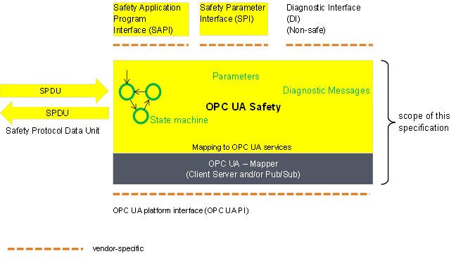
The basic communication layers of this document are shown in Figure 2.
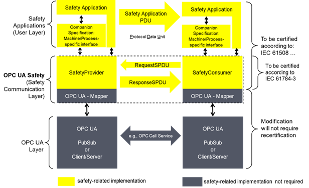
Figure 2 – Safety layer architecture
Summary of the architecture:
Part: User Layer
The safety applications in the User Layer are either directly connected to the SafetyProvider or SafetyConsumer, or they are connected via a machine-specific or process-specific interface, which is described in companion specifications (e.g. sectoral).
The safety applications are expected to be designed and implemented according to the IEC 61508 series.
The Safety applications in the User Layer are not within the scope of this document.
Part: OPC UA Safety (Safety Communication Layer)
This layer is within the scope of this document. It defines the two services SafetyProvider and SafetyConsumer as basic building blocks. Together, they form the safety communication layer (SCL), implemented in a safety-related way according to the IEC 61508 series.
SafetyData is transmitted using point-to-point communication (unidirectional). Each unidirectional data flow internally communicates in both directions, using a requestand response pattern. This allows for checking the timeliness of messages using a single clock in the SafetyConsumer, thus eliminating the necessity for synchronized clocks.
When SafetyConsumers connect to SafetyProviders, they have prior expectations regarding the pair of SafetyProviderID and SafetyBaseID (e.g. by configuration). If this expectation is not fulfilled by the SafetyProvider, fail-safe substitute values are delivered to the safety application instead of the received process values. In contrast, it is not necessary for a SafetyProvider to know the SafetyConsumerID of the SafetyConsumer and will provide its process values to any SafetyConsumer requesting it.
SafetyProviders can not detect communication errors. All required error detection is performed by the SafetyConsumer.
If it is necessary for a pair of safety applications to exchange SafetyData in both directions, two pairs of SafetyProviders and SafetyConsumers shall be established, one pair for each direction.
The OPC UA Mapper implements the parts of the safety communication layer which are specific for the OPC UA communication Service in use, i.e. PubSub or Client/Server. Therefore, the remaining parts of the safety communication layer can be implemented independent of the OPC UA Service being used.
Part: OPC UA Layer
Client/Server:
· The SafetyProvider is implemented using an OPC UA Server providing a Method.
· The SafetyConsumer is implemented using an OPC UA Client calling the Method provided by the SafetyProvider.
PubSub:
· The SafetyProvider publishes the ResponseSPDU and subscribes to the RequestSPDU.
· The SafetyConsumer publishes the RequestSPDU and subscribes to the ResponseSPDU.
[RQ5.4] Any CRC signature calculation shall start with a preset value of “1”.
[RQ5.5] Any CRC signature calculation resulting in a “0” value, shall use the value “1” instead.
[RQ5.6] SPDUs with all values (incl. CRC signature) being zero shall be ignored by the receiver (SafetyConsumer and SafetyProvider). For Client/Server communication, this means that a Method Call with all fields making up the RequestSPDU being zero shall be answered with all fields making up the ResponseSPDU being zero. Neither of these SPDUs shall be presented to the respective state machines.
Clause 6 describes the integration of this document into the OPC UA Information Models in 6.2 and the resulting Service interfaces in 6.3. Diagnostic services are described in 6.4.
Subclause 6.2 describes the identifiers, types and structure of the Objects and Methods that are used to implement the OPC UA mappers defined in this document. This implementation serves three purposes:
· support of the safe exchange of SPDUs at runtime
· online browsing, to identify SafetyConsumers and SafetyProviders, and to check their parameters for diagnostic purposes
· offline engineering: the Information Model of one controller can be exported in a standardized file on its engineering system, be imported in another engineering system, and finally deployed on another controller. This allows for a vendor-independent exchange of the communication interfaces of safety applications, e.g. for establishing connections between devices.
NOTE Neither online browsing nor offline engineering currently supports any features to detect errors. Hence, no guarantees with respect to functional safety are made. This means that online browsing can only be used for diagnostic purposes, and not for exchanging safety-relevant data. It is assumed that errors can occur during the transfer of the Information Model from one engineering system to another in the context of offline engineering. Therefore, the programmer of the safety application is responsible for the verification and validation of the safety application.
Consequently, all type values described in 6.2 are defined as read-only, i.e. they cannot be written by general OPC UA write commands.
[RQ6.1] Each Server shall have a singleton Folder called SafetyACSet with a fixed NodeID in the Namespace of this document. Because all SafetyProviders and SafetyConsumers on this Server contain a hierarchical Reference from this Object to themselves, it can be used to directly access all SafetyProviders and SafetyConsumers. SafetyACSet is intended for safety-related purposes only. It should not reference non-safety-related items.
See Table 3 for the definition of the SafetyACSet.
Table 3 – SafetyACSet definition
|
Attribute |
Value |
||
|
BrowseName |
SafetyACSet |
||
|
References |
NodeClass |
BrowseName |
Comment |
|
OrganizedBy by the Objects Folder defined in OPC 10000-5. |
|||
|
HasTypeDefinition |
ObjectType |
FolderType |
Entry point for all SafetyProviders and SafetyConsumers |
|
Conformance Units |
|||
|
SafetyACSet |
|||
[RQ6.2] In addition, a Server shall comprise one OPC UA Object derived from DataType SafetyProviderType for each SafetyProvider it implements, and one OPC UA Object derived from DataType SafetyConsumerType for each SafetyConsumer it implements. The corresponding Information Models shown in Figure 3 and Figure 4 shall be used.
A description of the graphical notation for the different types of Nodes and References (shown in Figure 3, Figure 4, and Figure 6) can be found in OPC UA 10000-3.
Figure 3 describes the SafetyProvider and the SafetyConsumer.
NOTE 1 This document assumes (atomic) consistent data exchange between OPC mappers of the two endpoints.
[RQ6.3a] For implementations supporting OPC UA Client/Server, the Call Service of the Method Service Set (see OPC UA 10000-4) shall be used. The Method ReadSafetyData has a set of input arguments that make up the RequestSPDU and a set of output arguments that make up the ResponseSPDU. The SafetyConsumer uses the OPC UA Client with the OPC UA Service Call.
[RQ6.3b] For implementations supporting OPC UA PubSub, the OPC UA Object SafetyPDUs with its Properties RequestSPDU and ResponseSPDU shall be used. RequestSPDU is published by the SafetyConsumer and subscribed by the SafetyProvider. ResponseSPDU is published by the SafetyProvider and subscribed by the SafetyConsumer.
NOTE 2 The terms “request” and “response” refer to the behaviour on the layer of this document. Within the PubSub context, both requests and responses are realized by repeatedly publishing and subscribing Messages, see Figure 14.
[RQ6.4] For diagnostic purposes, the SPDUs received and sent shall be accessible by calling the Method ReadSafetyDiagnostics.
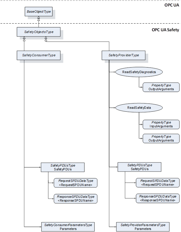
Figure 3 – Server Objects for OPC UA Safety
NOTE 3 For the input/output arguments of the Methods ReadSafetyData and ReadSafetyDiagnostics, see 6.2.2.3 and 6.2.2.4. For the parameters of the SafetyProvider and SafetyConsumer, see Figure 6, Table 12, and Table 13. For RequestSPDU and ResponseSPDU, see Table 7, Table 18, Table 20, and 7.2.1.
Figure 4 shows the instances of Server Objects for this document. The ObjectType for the SafetyProviderType contains Methods having outputs of the abstract DataType Structure. Each instance of a SafetyProvider requires its own copy of the Methods which contain the concrete DataTypes for OutSafetyData and OutNonSafetyData.
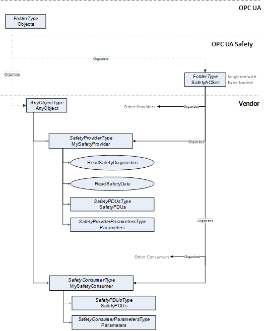
Figure 4 – Instances of Server Objects for this document
[RQ6.5] To reduce the number of variations and to alleviate validation testing, the following restrictions apply to instances of SafetyProviderType and SafetyConsumerType (or instances of DataTypes derived from SafetyProviderType or SafetyConsumerType):
1) The references shown in Figure 4 originating at SafetyProviderType or SafetyConsumerType and below shall be of ReferenceType HasComponent (and shall not be derived from ReferenceType HasComponent) for Object References or ReferenceType HasProperty (and shall not be derived from ReferenceType HasProperty) for Property References.
2) As BrowseNames (i.e. name and Namespace) are used to find Methods, the names of Objects and Properties shall be locally unique.
3) The DataType of both Properties and MethodArguments shall be used as specified, and no derived DataTypes shall be used (exception: OutSafetyData and OutNonSafetyData).
4) In IEC 62541, the order of Method arguments is relevant.
See Table 4 for the definition of the SafetyObjectsType.
Table 4 – SafetyObjectsType definition
|
Attribute |
Value |
||||
|
BrowseName |
SafetyObjectsType |
||||
|
IsAbstract |
True |
||||
|
References |
Node class |
BrowseName |
DataType |
TypeDefinition |
Modelling rule |
|
Subtype of BaseObjectType |
|||||
|
Conformance units |
|||||
|
SafetySupport |
|||||
See Table 5 for the definition of the SafetyProviderType.
Table 5 – SafetyProviderType definition
|
Attribute |
Value |
||||
|
BrowseName |
SafetyProviderType |
||||
|
IsAbstract |
False |
||||
|
References |
Node class |
BrowseName |
DataType |
TypeDefinition |
Modelling rule |
|
Subtype of SafetyObjectsType |
|||||
|
HasComponent |
Method |
ReadSafetyData |
|
|
Optional |
|
HasComponent |
Method |
ReadSafetyDiagnostics |
|
|
Optional |
|
HasComponent |
Object |
SafetyPDUs |
|
SafetyPDUsType |
Optional |
|
HasComponent |
Object |
Parameters |
|
SafetyProviderParametersType |
Mandatory |
|
Conformance units |
|||||
|
SafetyProviderParameters |
|||||
[RQ6.6] Instances of SafetyProviderType shall use non-abstract DataTypes for the arguments OutSafetyData and OutNonSafetyData.
See Table 6 for the definition of the SafetyConsumerType.
Table 6 – SafetyConsumerType definition
|
Attribute |
Value |
||||
|
BrowseName |
SafetyConsumerType |
||||
|
IsAbstract |
False |
||||
|
References |
Node class |
BrowseName |
DataType |
TypeDefinition |
Modelling rule |
|
Subtype of SafetyObjectsType |
|||||
|
HasComponent |
Object |
SafetyPDUs |
|
SafetyPDUsType |
Optional |
|
HasComponent |
Object |
Parameters |
|
SafetyConsumerParametersType |
Mandatory |
|
Conformance units |
|||||
|
SafetyConsumerParameters |
|||||
This Method is mandatory for the Facet SafetyProviderServerMapper. It is used to read SafetyData from the SafetyProvider. It is in the responsibility of the safety application that this Method is not concurrently called by multiple SafetyConsumers. Otherwise, the SafetyConsumer can receive invalid responses resulting in a safe reaction which can lead to either spurious trips or system unavailability, or both.
See Table 7 for Method ReadSafetyData’s arguments and Table 8 for its AdressSpace definition.
The Method argument OutSafetyData has an application-specific DataType derived from Structure. This DateType (including the DataTypeID) is expected to be the same in both the SafetyProvider and the SafetyConsumer. Otherwise, the SafetyConsumer will not accept the transferred data and switch to fail-safe substitute values instead (see state S16 in Table 34 as well as 7.2.3.2 and 7.2.3.5). The Method argument OutNonSafetyData has an application-specific DataType derived from Structure.
Signature
ReadSafetyData (
[in] UInt32 InSafetyConsumerID,
[in] UInt32 InMonitoringNumber,
[in] InFlagsType InFlags,
[out] Structure OutSafetyData,
[out] OutFlagsType OutFlags,
[out] UInt32 OutSPDU_ID_1,
[out] UInt32 OutSPDU_ID_2,
[out] UInt32 OutSPDU_ID_3,
[out] UInt32 OutSafetyConsumerID,
[out] UInt32 OutMonitoringNumber,
[out] UInt32 OutCRC,
[out] Structure OutNonSafetyData)
;
Table 7 – ReadSafetyData Method arguments
|
Argument |
Description |
|
|
InSafetyConsumerID |
“Safety Consumer Identifier”, see SafetyConsumerID in Table 23. |
|
|
InMonitoringNumber |
“MonitoringNumber of the RequestSPDU”, see 7.2.1.3 and MonitoringNumber in Table 23. |
|
|
InFlags |
“Octet with non-safety-related flags from SafetyConsumer”, see 6.2.3.1. |
|
|
OutSafetyData |
“SafetyData”, see 7.2.1.5. |
|
|
OutFlags |
“Octet with safety-related flags from SafetyProvider”, see 6.2.3.2. |
|
|
OutSPDU_ID_1 |
“Safety PDU Identifier Part1”, see 7.2.3.2. |
|
|
OutSPDU_ID_2 |
“Safety PDU Identifier Part2”, see 7.2.3.2. |
|
|
OutSPDU_ID_3 |
“Safety PDU Identifier Part3”, see 7.2.3.2. |
|
|
OutSafetyConsumerID |
“Safety Consumer Identifier”, see SafetyConsumerID in Table 23 and Table 26. |
|
|
OutMonitoringNumber |
MonitoringNumber of the ResponseSPDU, see 7.2.1.9, 7.2.3.1, and Figure 11. |
|
|
OutCRC |
CRC over the ResponseSPDU, see 7.2.3.6. |
|
|
OutNonSafetyData |
“Non-safe data” see 7.2.1.11. |
|
Table 8 – ReadSafetyData Method AddressSpace definition
|
Attribute |
Value |
||||
|
BrowseName |
ReadSafetyData |
||||
|
References |
NodeClass |
BrowseName |
DataType |
TypeDefinition |
ModellingRule |
|
HasProperty |
Variable |
InputArguments |
Argument[] |
PropertyType |
Mandatory |
|
HasProperty |
Variable |
OutputArguments |
Argument[] |
PropertyType |
Mandatory |
|
Conformance units |
|||||
|
ReadSafetyData |
|||||
This Method is mandatory for the Facet SafetyProviderServerMapper and optional for the Facet SafetyProviderPubSubMapper. It is provided for each SafetyProvider serving as a Diagnostic Interface, see 6.4.3.
See Table 9 for the arguments of Method ReadSafetyDiagnostics and Table 10 for its AddressSpace definition.
The Method arguments OutSafetyData and OutNonSafetyData are application-specific types derived from Structure.
Signature
ReadSafetyDiagnostics (
[out] UInt32 InSafetyConsumerID,
[out] UInt32 InMonitoringNumber,
[out] InFlagsType InFlags,
[out] Structure OutSafetyData,
[out] OutFlagsType OutFlags,
[out] UInt32 OutSPDU_ID_1,
[out] UInt32 OutSPDU_ID_2,
[out] UInt32 OutSPDU_ID_3,
[out] UInt32 OutSafetyConsumerID,
[out] UInt32 OutMonitoringNumber,
[out] UInt32 OutCRC,
[out] Structure OutNonSafetyData)
;
Table 9 – ReadSafetyDiagnostics Method arguments
|
Argument |
Description |
|
|
InSafetyConsumerID |
see Table 7 |
|
|
InMonitoringNumber |
see Table 7 |
|
|
InFlags |
see Table 7 |
|
|
OutSafetyData |
see Table 7 |
|
|
OutFlags |
see Table 7 |
|
|
OutSPDU_ID_1 |
see Table 7 |
|
|
OutSPDU_ID_2 |
see Table 7 |
|
|
OutSPDU_ID_3 |
see Table 7 |
|
|
OutSafetyConsumerID |
see Table 7 |
|
|
OutMonitoringNumber |
see Table 7 |
|
|
OutCRC |
see Table 7 |
|
|
OutNonSafetyData |
see Table 7 |
|
Table 10 – ReadSafetyDiagnostics Method AddressSpace definition
|
Attribute |
Value |
||||
|
BrowseName |
ReadSafetyDiagnostics |
||||
|
References |
NodeClass |
BrowseName |
DataType |
TypeDefinition |
ModellingRule |
|
HasProperty |
Variable |
OutputArguments |
Argument[] |
PropertyType |
Mandatory |
|
Conformance units |
|||||
|
ReadSafetyDiagnostics |
|||||
This Object is mandatory for the Facet SafetyProviderPubSubMapper and the Facet SafetyConsumerPubSubMapper It is used by the SafetyProvider to subscribe to the RequestSPDU and to publish the ResponseSPDU. The DataType of RequestSPDU is structured in the same way as the input arguments of ReadSafetyData. The DataType of ResponseSPDU is structured in the same way as the output arguments of ReadSafetyData.
See Table 11 for the definition of the SafetyPDUsType.
Both variables in the SafetyPDUsType have a counterpart within the Information Model of the SafetyConsumer. The SafetyConsumer publishes the RequestSPDU and subscribes to the ResponseSPDU.
Table 11 – SafetyPDUsType definition
|
Attribute |
Value |
|||||
|
BrowseName |
SafetyPDUsType |
|||||
|
IsAbstract |
False |
|||||
|
References |
Node class |
BrowseName |
DataType |
TypeDefinition |
Modelling rule |
|
|
Subtype of BaseObjectType |
||||||
|
HasComponent |
Variable |
<RequestSPDU> |
RequestSPDUDataType |
BaseDataVariableType |
Mandatory Placeholder |
|
|
HasComponent |
Variable |
<ResponseSPDU> |
ResponseSPDUDataType |
BaseDataVariableType |
Mandatory Placeholder |
|
|
Conformance units |
|
|||||
|
SafetyPDUs |
||||||
The Object SafetyPDUs shall contain exactly one Reference to a Variable of DataType RequestSPDUDataType and exactly one Reference to a Variable of a subtype of DataType ResponseSPDUDataType.
For example, Figure 5 shows a distributed safety application with four SafetyAutomationComponents. It is assumed that SafetyAutomationComponent 1 sends a value to the other three SafetyAutomationComponents using three SafetyProviders, each comprising a pair of SPDUs. For each recipient, there is an individual pair of SPDUs.
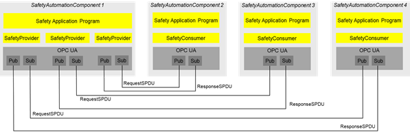
Figure 5 – Safety multicast with three recipients using IEC 62541 PubSub
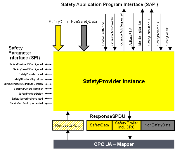
Figure 6 shows the safety parameters for the SafetyProvider and the SafetyConsumer.
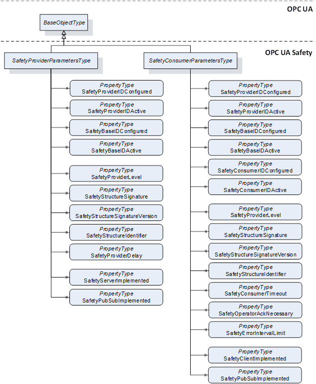
Figure 6 – Safety parameters for the SafetyProvider and the SafetyConsumer
Table 12 shows the definition for the SafetyProviderParametersType. Refer to 6.3.3.3 for more details on the Safety Parameter Interface (SPI) of the SafetyProvider.
Table 12 – SafetyProviderParametersType definition
|
Attribute |
Value |
||||
|
BrowseName |
SafetyProviderParametersType |
||||
|
IsAbstract |
False |
||||
|
References |
Node class |
BrowseName |
DataType |
TypeDefinition |
Modelling rule |
|
Subtype of BaseObjectType |
|||||
|
HasProperty |
Variable |
SafetyProviderIDConfigured |
UInt32 |
PropertyType |
Mandatory |
|
HasProperty |
Variable |
SafetyProviderIDActive |
UInt32 |
PropertyType |
Mandatory |
|
HasProperty |
Variable |
SafetyBaseIDConfigured |
Guid |
PropertyType |
Mandatory |
|
HasProperty |
Variable |
SafetyBaseIDActive |
Guid |
PropertyType |
Mandatory |
|
HasProperty |
Variable |
SafetyProviderLevel |
Byte |
PropertyType |
Mandatory |
|
HasProperty |
Variable |
SafetyStructureSignature |
UInt32 |
PropertyType |
Mandatory |
|
HasProperty |
Variable |
SafetyStructureSignatureVersion |
UInt16 |
PropertyType |
Mandatory |
|
HasProperty |
Variable |
SafetyStructureIdentifier |
String |
PropertyType |
Mandatory |
|
HasProperty |
Variable |
SafetyProviderDelay |
UInt32 |
PropertyType |
Mandatory |
|
HasProperty |
Variable |
SafetyServerImplemented |
Boolean |
PropertyType |
Mandatory |
|
HasProperty |
Variable |
SafetyPubSubImplemented |
Boolean |
PropertyType |
Mandatory |
|
Conformance units |
|||||
|
SafetyProviderParameters |
|||||
The parameters for SafetyProviderID and SafetyBaseID exist in pairs for “Configured” and “Active” states:
· SafetyProviderIDConfigured and SafetyProviderIDActive,
· SafetyBaseIDConfigured and SafetyBaseIDActive.
The “[...]Configured” parameters shall always deliver the values as configured via the SPI. The “[...]Active” parameters shall deliver:
· the corresponding “[...]Configured” values if the system is still offline;
· the values which have been set during runtime via the SAPI parameters (SafetyProviderID, SafetyBaseID);
· the corresponding “[...]Configured” values if the active values have been set to zero via the SAPI parameters (SafetyProviderID, SafetyBaseID).
The Property SafetyBaseIDConfigured is shared for all SafetyProviders with the same SafetyBaseIDConfigured value. If multiple instances of SafetyObjectsType are running on the same Node, it is a viable optimization that a Property SafetyBaseIDConfigured is referenced by either multiple SafetyProviders or SafetyConsumers, or both.
For releases up to Release 2.0 of the document, the value for the SafetyStructureSignatureVersion shall be 0x0001 (see RQ7.21 in 7.2.3.5).
Table 13 shows the definition of the SafetyConsumerParametersType. The Properties SafetyStructureIdentifier and SafetyStructureSignatureVersion are optional, because SafetyStructureSignature is typically calculated in an offline engineering tool. For small devices, it could be beneficial to only upload the SafetyStructureSignature to the device, but not SafetyStructureIdentifier and SafetyStructureSignatureVersion in order to save either bandwidth or memory, or both. Refer to 6.3.4.4 for more details on the Safety Parameter Interface (SPI) of the SafetyConsumer.
Table 13 – SafetyConsumerParametersType definition
|
Attribute |
Value |
||||
|
BrowseName |
SafetyConsumerParametersType |
||||
|
IsAbstract |
False |
||||
|
References |
Node class |
BrowseName |
DataType |
TypeDefinition |
Modelling rule |
|
Subtype of BaseObjectType |
|||||
|
HasProperty |
Variable |
SafetyProviderIDConfigured |
UInt32 |
PropertyType |
Mandatory |
|
HasProperty |
Variable |
SafetyProviderIDActive |
UInt32 |
PropertyType |
Mandatory |
|
HasProperty |
Variable |
SafetyBaseIDConfigured |
Guid |
PropertyType |
Mandatory |
|
HasProperty |
Variable |
SafetyBaseIDActive |
Guid |
PropertyType |
Mandatory |
|
HasProperty |
Variable |
SafetyConsumerIDConfigured |
UInt32 |
PropertyType |
Mandatory |
|
HasProperty |
Variable |
SafetyConsumerIDActive |
UInt32 |
PropertyType |
Mandatory |
|
HasProperty |
Variable |
SafetyProviderLevel |
Byte |
PropertyType |
Mandatory |
|
HasProperty |
Variable |
SafetyStructureSignature |
UInt32 |
PropertyType |
Mandatory |
|
HasProperty |
Variable |
SafetyStructureSignatureVersion |
UInt16 |
PropertyType |
Optional |
|
HasProperty |
Variable |
SafetyStructureIdentifier |
String |
PropertyType |
Optional |
|
HasProperty |
Variable |
SafetyConsumerTimeout |
UInt32 |
PropertyType |
Mandatory |
|
HasProperty |
Variable |
SafetyOperatorAckNecessary |
Boolean |
PropertyType |
Mandatory |
|
HasProperty |
Variable |
SafetyErrorIntervalLimit |
UInt16 |
PropertyType |
Mandatory |
|
HasProperty |
Variable |
SafetyClientImplemented |
Boolean |
PropertyType |
Mandatory |
|
HasProperty |
Variable |
SafetyPubSubImplemented |
Boolean |
PropertyType |
Mandatory |
|
Conformance units |
|||||
|
SafetyConsumerParameters |
|||||
The parameters for SafetyProviderID, SafetyBaseID and SafetyConsumerID exist in pairs for “Configured” and “Active” states: SafetyProviderIDConfigured and SafetyProviderIDActive, SafetyBaseIDConfigured and SafetyBaseIDActive, and SafetyConsumerIDConfigured and SafetyConsumerIDActive.
The “[...]Configured” parameters shall always deliver the values as configured via the SPI. The “[...]Active” parameters shall deliver:
· the corresponding “[...]Configured” values if the system is still offline;
· the values which have been set during runtime via the SAPI parameters (SafetyProviderID, SafetyBaseID, SafetyConsumerID);
· the corresponding “[...]Configured” values if the active values have been set to zero via the SAPI parameters (SafetyProviderID, SafetyBaseID, SafetyConsumerID).
The InFlagsType a subtype of the Byte DataType with the OptionSetValues Property defined. The InFlagsType is formally defined in Table 14.
CommunicationError can be used as a trigger, e.g. for a communication analysis tool. It is not forwarded to the safety application by the SafetyProvider. If CommunicationError is necessary in the safety application, bidirectional communication can be implemented and the value of CommunicationError can be put into the user data.
Table 14 – InFlagsType values
|
Value |
Bit no. |
Description |
|
CommunicationError |
0 |
0: No error 1: An error was detected in the previous ResponseSPDU. |
|
OperatorAckRequested |
1 |
Used to inform the SafetyProvider that operator acknowledgment is requested. |
|
FSV_Activated |
2 |
Used for conformance test of SafetyConsumer.SAPI.FSV_Activated. |
Bits 3 to 7 are reserved for future use and shall be set to zero by the SafetyConsumer. They shall not be evaluated by the SafetyProvider.
The InFlagsType representation in the AddressSpace is defined in Table 15.
Table 15 – InFlagsType dDefinition
|
Attribute |
Value |
|||||
|
BrowseName |
InFlagsType |
|||||
|
IsAbstract |
False |
|||||
|
References |
NodeClass |
BrowseName |
DataType |
TypeDefinition |
Other |
|
|
Subtype of the Byte DataType defined in OPC 10000-3 |
||||||
|
0:HasProperty |
Variable |
0:OptionSetValues |
0:LocalizedText [] |
0:PropertyType |
|
|
|
Conformance units |
||||||
|
SafetySupport |
||||||
The OutFlagsType is a subtype of the Byte DataType with the OptionSetValues Property defined. The OutFlagsType is formally defined in Table 16.
Table 16 – OutFlagsType values
|
Value |
Bit no. |
Description |
|
OperatorAckProvider |
0 |
Operator acknowledgment at the provider, hereby forwarded to the SafetyConsumer, see OperatorAckProvider in the SAPI of the SafetyProvider, 6.3.3.2. |
|
ActivateFSV |
1 |
Activation of fail-safe values by the safety application at the SafetyProvider, hereby forwarded to the SafetyConsumer, see ActivateFSV in the SAPI of the SafetyProvider, 6.3.3.2. |
|
TestModeActivated |
2 |
Enabling and disabling of test mode in the SafetyProvider, hereby forwarded to the SafetyConsumer, see EnableTestMode in the SAPI of the SafetyProvider, 6.3.3.2. |
Bits 3 to 7 are reserved for future use and shall be set to zero by the SafetyProvider. They shall not be evaluated by the SafetyConsumer.
The OutFlagsType representation in the AddressSpace is defined in Table 17.
Table 17 – OutFlagsType dDefinition
|
Attribute |
Value |
|||||
|
BrowseName |
OutFlagsType |
|||||
|
IsAbstract |
False |
|||||
|
References |
NodeClass |
BrowseName |
DataType |
TypeDefinition |
Other |
|
|
Subtype of the Byte DataType defined in OPC 10000-3 |
||||||
|
0:HasProperty |
Variable |
0:OptionSetValues |
0:LocalizedText [] |
0:PropertyType |
|
|
|
Conformance units |
||||||
|
SafetySupport |
||||||
Table 18 shows the definition of the RequestSPDUDataType. The Prefix “In” is interpreted from the SafetyProvider’s point of view and is used in a consistent manner to the parameters of the Method ReadSafetyData (see 6.2.2.3).
Table 18 – RequestSPDUDataType structure
|
Name |
Type |
Description |
|
RequestSPDUDataType |
structure |
|
|
InSafetyConsumerID |
UInt32 |
See corresponding Method argument in Table 7. |
|
InMonitoringNumber |
UInt32 |
See corresponding Method argument in Table 7. |
|
InFlags |
InFlagsType |
See corresponding Method argument in Table 7. |
The representation in the AddressSpace of the RequestSPDUDataType is defined in Table 19.
Table 19 – RequestSPDUDataType definition
|
Attributes |
Value |
||||
|
BrowseName |
RequestSPDUDataType |
||||
|
IsAbstract |
False |
||||
|
References |
NodeClass |
BrowseName |
DataType |
TypeDefinition |
ModellingRule |
|
Subtype of Structure defined in OPC 10000-3. |
|||||
|
Conformance units |
|||||
|
SafetyPDUs |
|||||
Table 20 shows the ResponseSPDUDataType Structure. The Prefix “Out” is interpreted from the SafetyProvider’s point of view and is used in a consistent manner to the parameters of the Method ReadSafetyData (see 6.2.2.3).
Table 20 – ResponseSPDUDataType structure
|
Name |
Type |
Description |
|
ResponseSPDUDataType |
structure |
|
|
OutFlags |
OutFlagsType |
See corresponding Method argument in Table 7. |
|
OutSPDU_ID_1 |
UInt32 |
See corresponding Method argument in Table 7. |
|
OutSPDU_ID_2 |
UInt32 |
See corresponding Method argument in Table 7. |
|
OutSPDU_ID_3 |
UInt32 |
See corresponding Method argument in Table 7. |
|
OutSafetyConsumerID |
UInt32 |
See corresponding Method argument in Table 7. |
|
OutMonitoringNumber |
UInt32 |
See corresponding Method argument in Table 7. |
|
OutCRC |
UInt32 |
See corresponding Method argument in Table 7. |
[RQ6.7] To define the concrete DataType for the ResponseSPDU (which specifies the concrete DataTypes for SafetyData and NonSafetyData, respectively), proceed as follows: (1) Derive a concrete DataType from the abstract ResponseSPDUDataType. (2) In doing so, add the following fields to the Structure in the given order: (a) First, field OutSafetyData with the concrete Structure DataType for the SafetyData (see 7.2.1.5). (b) Second, field NonSafetyData with the concrete Structure DataType for the NonSafetyData (or a placeholder DataType, see requirement RQ6.8).
[RQ6.8] To avoid possible problems with empty Structures, the dummy Structure NonSafetyDataPlaceholder shall be used as DataType for OutNonSafetyData when no NonSafetyData is used. The DataType Node defining this Structure has a fixed NodeID and contains a single Boolean.
The representation in the AddressSpace of the ResponseSPDUDataType is defined in Table 21.
Table 21 – ResponseSPDUDataType definition
|
Attributes |
Value |
||||
|
BrowseName |
ResponseSPDUDataType |
||||
|
IsAbstract |
True |
||||
|
References |
NodeClass |
BrowseName |
DataType |
TypeDefinition |
ModellingRule |
|
Subtype of Structure defined in OPC 10000-3 |
|||||
|
Conformance units |
|||||
|
SafetyPDUs |
|||||
Table 22 shows the definition of the NonSafetyDataPlaceholderDataType. The receiver shall not evaluate the value of ‘dummy’.
Table 22 – NonSafetyDataPlaceholderDataType structure
|
Name |
Type |
Description |
|
NonSafetyDataPlaceholderDataType |
Structure |
|
|
Dummy |
Boolean |
Dummy Variable to avoid empty structures. |
Future versions may use different identifiers (such as ReadSafetyDataV2 for the Method when using Client/Server communication or RequestSPDUV2DataType and ResponseSPDUV2DataType for the SPDU DataTypes when using PubSub communication), allowing a SafetyProvider to implement multiple versions of this document at the same time. Hence, the same SafetyProvider can be accessed by SafetyConsumers of different versions.
This document supports sending of the Built-in and Simple DataTypes specified in OPC UA (see OPC 10000-3 and OPC 10000-6) within SafetyData. The supported DataTypes are vendor-specific.
[RQ6.9] Only scalar DataTypes shall be used. Arrays are currently not supported by this document.
The supported maximum length of the SafetyData is vendor-specific but still limited to 1 500 octets. Typical values for the maximum length include 1 octet, 16 octets, 64 octets, 256 octets, 1 024 octets, and 1 500 octets.
[RQ6.10] For controller-like devices, the supported DataTypes and the maximum length of the SafetyData shall be listed in the user manual.
[RQ6.11] For the DataType Boolean, the value 0x01 shall be used for ‘true’ and the value 0x00 shall be used for ‘false’.
It is recommended to send multiple Booleans in separate variables. However, in small devices, it can be necessary to combine a set of 8 Booleans in one Variable for performance reasons. In this case, the DataType Byte can be used.
This document uses the OPC UA services for connection establishment, it poses no additional requirement to these services.
This version of the document describes configuration only at engineering time. This means that the parameters defined in the SPI (see 6.3.3.3 and 6.3.4.4) are read-only via the interface described in this document. Changing of parameters is expected to be done in a safety-related way, using the respective tools and interfaces provided by the vendor. Future versions of this document may specify a vendor-independent interface for configuration.
Figure 7 gives an overview of the safety communication layer and its interfaces. It thereby also shows the scope of this document. The main function of the layer services is the state machine which handles the protocol. The state machines interact with the following interfaces:
– The Safety Application Program Interface (SAPI) is accessed by the safety application for exchanging SafetyData during runtime.
– The Safety Parameter Interface (SPI) is accessed during commissioning for setting safety parameters such as IDs or the timeout value in the SafetyConsumer.
– The non-safety related Diagnostic Interface (DI) can be accessed at runtime for troubleshooting the safety communication.
The OPC UA Platform Interface (OPC UA PI) connects the SCL to the non-safe OPC UA stack and is used during runtime.
The interfaces (SAPI, SPI, DI and OPC UA PI) described in 6.3 are abstract and informative. They represent logical data inputs and outputs to this layer that are necessary for the proper operation of the state machine. No normative, concrete mappings are specified. The concrete implementations are vendor-specific and do no necessarily exactly match the abstract interfaces described in this document.
Figure 7 – Safety communication layer overview
The state machines of this document are independent from the actual OPC UA services used for data transmission. This is accomplished by introducing a so-called OPC UA Mapper, serving as an interface between the safety communication layer and the OPC UA stack.
The mapper can either make use of OPC UA Client/Server and remote Method invocation or the publishing of and subscribing to remote Variables as defined in OPC 10000-14. The requirements on the implementation of the mapper are implicitly given in 6.2.
Figure 8 shows an overview of the SafetyProvider interfaces. The SAPI is specified in 6.3.3.2, the SPI is specified in 6.3.3.3.
Figure 8 – SafetyProvider interfaces
[RQ6.12] The SAPI of the SafetyProvider represents the safety communication layer services of the SafetyProvider. Table 23 lists all inputs and outputs of the SAPI of the SafetyProvider. Each SafetyProvider shall implement the SAPI as shown in Table 23, however, the details are vendor-specific.
Table 23 – SAPI of the SafetyProvider
|
SAPI Term |
Type |
I/O |
Definition |
|
SafetyData |
Structure |
I |
This input is used to accept the user data which is then transmitted as SafetyData in the SPDU. NOTE Whenever a new MNR is received from a SafetyConsumer, the state machine of the SafetyProvider will read a new value of the SafetyData from its corresponding Safety Application and use it until the next MNR is received. If no valid user data is available at the Safety Application, ActivateFSV can be set to “1” by the Safety Application. |
|
NonSafetyData |
Structure |
I |
Used to consistently transmit NonSafetyData values (e.g. diagnostic information) together with safe data, see 7.2.1.11 |
|
EnableTestMode |
Boolean |
I |
By setting this input to “1” the remote SafetyConsumer is informed (by Bit 2 in ResponseSPDU.Flags, see 6.2.3.2) that the SafetyData are test data, and are not to be used for safety-related decisions. NOTE This document is intended for implementation in safety devices exclusively, see requirement RQ4.1. |
|
Boolean |
I |
This input is used to implement an operator acknowledgment on the SafetyProvider side. The value will be forwarded to the SafetyConsumer, where it can be used to trigger a return from fail-safe substitute values (FSV) to actual process values (PV), see B.3.4. |
|
|
OperatorAckRequested |
Boolean |
O |
Indicates that an operator acknowledge is requested by the SafetyConsumer. This flag is received within the RequestSPDU. |
|
ActivateFSV |
Boolean |
I |
By setting this input to “1” the SafetyConsumer is instructed (via Bit 1 in ResponseSPDU.Flags, see 6.2.3.2) to deliver FSV instead of PV to the safety application program. NOTE If the replacement of process values by FSV is to be controllable in a more fine-grained way, this can be realized by using qualifiers within the SafetyData, see 6.3.6. |
|
SafetyConsumerID |
UInt32 |
O |
This output yields the ConsumerID used in the last access to this SafetyProvider by a SafetyConsumer (see 6.2.2.3). Since all safety-related checks are executed by an implementation of this document, the safety application is not required to check this SafetyConsumerID. |
|
MonitoringNumber |
UInt32 |
O |
This output yields the MonitoringNumber (MNR). It is updated whenever a new request comes in from the SafetyConsumer. |
|
SafetyProviderID |
UInt32 |
I |
For dynamic systems, this input can be set to a non-zero value. In this case, the SafetyProvider uses this value instead of the value from the SPI parameter SafetyProviderIDConfigured. If the value is changed to “0”, the value of parameter SafetyProviderIDConfigured from the SPI will be used (again). See Figure 8, 3.1.2.15, and 9.1.1. For static systems, this input is usually always kept at value “0”. |
|
SafetyBaseID |
Guid |
I |
For dynamic systems, this input can be set to a non-zero value. In this case, the SafetyProvider uses this value instead of the value of the SPI parameter SafetyBaseIDConfigured. If the value is changed to “0”, the value of parameter SafetyBaseIDConfigured from the SPI will be used (again). See Figure 8, 3.1.2.14, and 9.1.1. For static systems, this input is usually always kept at value “0”. |
[RQ6.13a] Each SafetyProvider shall implement the parameters and constants [RQ6.13b] as shown in Table 24. The parameters (R/W in column “Access”) can be set via the SPI, whereas the constants (R in column “Access”) are read-only. The mechanisms for setting the parameters are vendor-specific. The attempt of setting a parameter to a value outside its range, or of the setting of a read-only parameter, shall not become effective, and a diagnostic message should be shown when appropriate. The values of the constants depend on the way the SafetyProvider is implemented. They never change and are therefore not writable via any of the interfaces.
Table 24 – SPI of the SafetyProvider
|
Identifier |
Type |
Range |
Initial value (before configuration) |
Access |
Note |
|
SafetyProviderIDConfigured |
UInt32 |
0x0 to 0xFFFFFFFF |
0x0 |
R/W |
SafetyProviderID of the SafetyProvider that is normally used, see 3.1.2.15 and 9.1.1. For dynamic systems, the safety application program can overwrite this ID by providing a non-zero value at the input SafetyProviderID of the SafetyProvider’s SAPI. This runtime value can be queried using the SafetyProviderIDActive parameter. See 6.2.2.6 for details on configured and active values. NOTE If both the values provided at the SPI and the SAPI are 0x0, this means that the SafetyProvider is not properly configured. SafetyConsumers will never try to communicate with SafetyProviders having a SafetyProviderID of 0x0, see Transitions T13/T27 in Table 35 and the macro <ParametersOK?> in Table 33. |
|
SafetyBaseIDConfigured |
Guid |
Any value which can be represented with sixteen octets |
All sixteenoctets are 0x00 |
R/W |
SafetyBaseID of the SafetyProvider that is normally used, see 3.1.2.14 and 9.1.1. For dynamic systems, the safety application program can overwrite this ID by providing a non-zero value at the input SafetyBaseID of the SafetyProvider’s SAPI. This runtime value can be queried using the SafetyBaseIDActive parameter. See 6.2.2.6 for details on configured and active values. NOTE If both the values provided at the SPI and the SAPI are 0x0, this means that the SafetyProvider is not properly configured. SafetyConsumers will never try to communicate with SafetyProviders having a SafetyBaseID of 0x0, see Transitions T13/T27 in Table 35 and the macro <ParametersOK?> in Table 33. See 9.1.1 for more information on GUID. |
|
SafetyProviderLevel |
Byte |
0x01 to 0x04 |
n.a. |
R |
The SIL the SafetyProvider implementation (hardware and software) is capable of, see Figure 9. NOTE 1 It is independent from the generation of the SafetyData at SAPI. NOTE 2 The SafetyProviderLevel is used to distinguish devices of a different SIL. As a result, SPDUs coming from a device with a low SIL will never be accepted when a SafetyConsumer is parameterized to implement a safety function with a high SIL. |
|
SafetyStructureSignature |
UInt32 |
0x0 to 0xFFFFFFFF |
0x0 |
R/W |
Signature of the SafetyData structure, for calculation see 7.2.3.5. NOTE “0” would not be a valid signature and thus indicates a SafetyProvider which is not properly configured. SafetyConsumers will never try to communicate with SafetyProviders having a SafetyStructureSignature of 0x0, see Transitions T13/T27 in Table 35 and the macro <ParametersOK?> in Table 33. |
|
SafetyStructureSignatureVersion |
UInt16 |
0x1 |
0x1 |
R/W |
Version used to calculate SafetyStructureSignature, see 7.2.3.5 |
|
SafetyStructureIdentifier |
String |
all strings |
“” (the empty string) |
R/W |
Identifier describing the DataType of the SafetyData, see 7.2.3.5. |
|
SafetyProviderDelay |
UInt32 |
0x0 to 0xFFFFFFFF |
0x0 |
R/W |
In microseconds (µs). It can be set during the engineering phase of the SafetyProvider or set during online configuration as well. SafetyProviderDelay is the maximum time at the SafetyProvider from receiving the RequestSPDU to start the transmission of ResponseSPDU, see 8.1. The parameter SafetyProviderDelay has no influence on the functional behaviour of the SafetyProvider. Therefore, it is not necessary for this value to be generated in a safety-related way. However, it will be provided in the OPC UA Information Model of a SafetyProvider to inform about its worst-case delay time. The value can be used during commissioning to check whether the timing behaviour of the SafetyProvider is suitable to fulfill the watchdog delay of the corresponding SafetyConsumer. |
|
SafetyServerImplemented |
Boolean |
0x0 or 0x1 |
n.a. |
R |
This read-only parameter indicates whether the SafetyProvider has implemented the Server part of OPC UA Client/Server communication (see 5.4): 1: Server for OPC UA Client/Server communication is implemented. 0: Server for OPC UA Client/Server communication is not implemented. The corresponding Facets are SafetyProviderServer and SafetyProviderServerMapper. |
|
SafetyPubSubImplemented |
Boolean |
0x0 or 0x1 |
n.a. |
R |
This read-only parameter indicates whether the SafetyProvider has implemented the necessary publishers and subscribers for OPC UA PubSub communication (see 5.4): 1: OPC UA PubSub communication is implemented. 0: OPC UA PubSub communication is not implemented. The corresponding Facets are SafetyProviderPubSub and SafetyProviderPubSubMapper. |
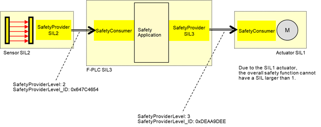
Figure 9 – Example combinations of SIL capabilities
The constant SafetyProviderLevel determines the value that is used for SafetyProviderLevel_ID when calculating the SPDU_ID, see 7.2.3.4.
NOTE SafetyProviderLevel is defined as the SIL the SafetyProvider implementation (hardware and software) is capable of, not to be confused with the SIL of the implemented safety function. For instance, Figure 9 shows a safety function which is implemented using a SIL2-capable sensor, a SIL3-capable PLC, and a SIL1-capable actuator. The overall SIL of the safety function is considered to be SIL1. Nevertheless, the SafetyProvider implemented on the sensor will use the constant value “2” as SafetyProviderLevel, whereas the SafetyProvider implemented on the PLC will use the constant value “3” as SafetyProviderLevel.
It is necessary for the respective SafetyConsumers (on the PLC and the actuator) to know the SafetyProviderLevel of their SafetyProviders in order to check the SPDU_ID (see 7.2.3.2).
Figure 10 shows an overview of the SafetyConsumer interfaces. The Safety Application Program Interface (SAPI) is specified in 6.3.4.2, the Safety Parameter Interface (SPI) is specified in 6.3.4.4.
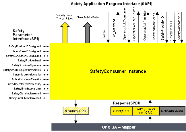
Figure 10 – SafetyConsumer interfaces
The SAPI of the SafetyConsumer represents the safety communication layer services of the SafetyConsumer. Table 25 lists all inputs and outputs of the SAPI of the SafetyConsumer.
[RQ6.14] Each SafetyConsumer shall implement the SAPI as shown in Table 25, however, the details are vendor-specific.
Table 25 – SAPI of the SafetyConsumer
|
SAPI Term |
Type |
I/O |
Definition |
|
SafetyData |
Structure |
O |
This output either delivers the process values received from the SafetyProvider in the SPDU field SafetyData, or FSV. |
|
NonSafetyData |
Structure |
O |
This output delivers the non-safety process values (e.g. diagnostic information) which were sent together with safe data, see 7.2.1.11 |
|
Enable |
Boolean |
I |
By changing this input to “0” the SafetyConsumer will change each and every Variable of the SafetyData to “0”1 and stop sending requests to the SafetyProvider. When changing Enable to “1” the SafetyConsumer will restart safe communication. The variable can be used to delay the start of the safety communication according to this document, after power on until “OPC UA connection ready” is set.The delay time is not monitored while enable is set to “0”. |
|
FSV_Activated |
Boolean |
O |
This output indicates via “1” that on the output SafetyData FSV (all binary “0”) are provided1. NOTE A ResponseSPDU which is checked with an error results in FSV_Activated being set to “1”, see T24 in Table 35. There could be other reasons. |
|
OperatorAckConsumer |
Boolean |
I |
For motivation, see 6.3.4.3. After an indication of OperatorAckRequested this input can be used to signal an operator acknowledgment. By changing this input from “0” to “1” (rising edge) the SafetyConsumer is instructed to switch SafetyData from FSV to PV. OperatorAckConsumer is processed only if this rising edge arrives after OperatorAckRequested was set to “1”, see Figure 19. If a rising edge of OperatorAckConsumer arrives before OperatorAckRequested becomes 1, this rising edge is ignored. |
|
Boolean |
O |
This output indicates the request for operator acknowledgment. The bit is set to “1” by the SafetyConsumer, when three conditions are met: 1) Too many communication errors were detected in the past, so the SafetyConsumer decided to switch to fail-safe substitute values. 2) Currently, no communication errors occur, and hence operator acknowledgment is possible. 3) Operator acknowledgment (rising edge at input OperatorAckConsumer) has not yet occurred. The bit is reset to “0” when a rising edge at OperatorAckConsumer is detected. |
|
|
Boolean |
O |
This output indicates that an operator acknowledgment has taken place on the SafetyProvider. If operator acknowledgment at the SafetyProvider should be allowed, this output is connected to OperatorAckConsumer, see B.3.4 and B.3.5. NOTE If the ResponseSPDU is checked with error, this output remains at its last value, see T24 in Table 35. |
|
|
TestModeActivated |
Boolean |
O |
The safety application program is expected to evaluate this output for determining whether the communication partner is in test mode or not. A value of “1” indicates that the communication partner (source of data) is in test mode, e.g. during commissioning. Data coming from a device in test mode may be used for testing but is not intended to be used to control safety-critical processes. A value of “0” represents the “normal” safety-related mode. The test mode enables the programmer and commissioner to validate the safety application using test data. NOTE If the ResponseSPDU check results in an error and the ErrorIntervalTimer (see 6.3.4.4) is also not expired, TestModeActivated is reset, see state S17_Error in Table 34. |
|
SafetyProviderID |
UInt32 |
I |
For dynamic systems, this input can be set to a non-zero value. In this case, the SafetyConsumer uses this variable instead of the SPI parameter SafetyProviderIDConfigured. This input is only read in the first cycle, or when a rising edge occurs at the input Enable. See also Table 26. If it is changed to “0”, the value of SPI parameter SafetyProviderIDConfigured will be used (again). For static systems, this input is usually always kept at value “0”. |
|
SafetyBaseID |
Guid |
I |
For dynamic systems, this input can be set to a non-zero value. In this case, the SafetyConsumer uses this variable instead of the SPI parameter SafetyBaseIDConfigured. This input is only read in the first cycle, or when a rising edge occurs at the input Enable. See also Table 26. If it is changed to “0”, the SPI parameter SafetyBaseIDConfigured will become activated. For static systems, this input is usually always kept at value “0”. |
|
SafetyConsumerID |
UInt32 |
I |
For dynamic systems, this input can be set to a non-zero value. In this case, the SafetyConsumer uses this variable instead of the SPI parameter SafetyConsumerID. This input is only read in the first cycle, or when a rising edge occurs at the input Enable. See also Table 26. If it is changed to “0”, the SPI parameter SafetyConsumerID will become activated. For static systems, this input is usually always kept at value “0”. |
|
1 If an application requires different FSV than “all binary 0”, it is expected to use appropriate constants and ignore the output of SafetyData whenever FSV_Activated is set. |
|||
The safety argumentation assumes that random errors in the underlying OPC UA stack including its communication links are not too frequent, i.e. that its failure rate is lower than a given threshold, depending on the desired SIL (see 9.3.1).
Whenever the SafetyConsumer detects a faulty message, it checks whether the assumption is still valid, and switches to fail-safe substitute values otherwise. Returning to process values then requires an operator acknowledgment.
Operator Acknowledge is expected to be initiated by a human operator who is responsible to check the installation, see Table 40, row “Operator Acknowledge”. For this reason, the parameter OperatorAckRequested is delivered by the SafetyConsumer to the safety application. See Clause B.2 for details on operator acknowledgment scenarios.
Timeout errors do only require an operator acknowledgment if operator acknowledgment is required by the safety function itself. In this case, SafetyOperatorAckNecessary is set to indicate that operator acknowledgments are required. See 6.3.4.5 for details.
[RQ6.15a] Each SafetyConsumer shall implement the parameters and constants [RQ6.15b] as shown in Table 26. The parameters (R/W in column “Access”) can be set via the SPI, whereas the constants (R in column “Access”) are read-only. The mechanisms for setting these parameters are vendor-specific. The attempt of setting a parameter to a value outside its range, or of the setting of a read-only parameter, shall not become effective, and a diagnostic message should be shown when appropriate. The SPI of the SafetyConsumer represents the parameters of the safety communication layer management of the SafetyConsumer. The values of the constants depend on the way the SafetyConsumer is implemented. They never change and are therefore not writable via any of the interfaces.
Table 26 – SPI of the SafetyConsumer
|
Identifier |
Type |
Valid range |
Initial value (before configuration) |
Access |
Note |
|
SafetyProviderIDConfigured |
UInt32 |
0x0 to 0xFFFFFFFF |
0x0 |
R/W |
The default SafetyProviderID of the SafetyProvider this SafetyConsumer uses to make a connection, see Figure 8 and 3.1.2.15. For dynamic systems, the safety application program can overwrite this ID by providing a non-zero value at the input SafetyProviderID of the SafetyConsumer’s SAPI. This runtime value can be queried using the SafetyProviderIDActive parameter. See 6.2.2.6 for details on configured and active values. |
|
SafetyBaseIDConfigured |
Guid |
Any value which can be represented with sixteen octets. |
All sixteen octets are 0x0 |
R/W |
The default SafetyBaseID of the SafetyProvider this SafetyConsumer uses to make a connection, see 3.1.2.14. For dynamic systems, the safety application program can overwrite this ID by providing a non-zero value at the input SafetyBaseID of the SafetyConsumer’s SAPI. This runtime value can be queried using the SafetyBaseIDActive parameter. See 6.2.2.6 for details on configured and active values. See 9.1.1 for more information on GUID. |
|
SafetyConsumerIDConfigured |
UInt32 |
0x0 to 0xFFFFFFFF |
0x0 |
R/W |
SafetyConsumerID of the SafetyConsumer, see 9.1.2. For dynamic systems, the safety application program can overwrite this ID by providing a non-zero value at the input SafetyConsumerID of the SafetyConsumer’s SAPI. This runtime value can be queried using the SafetyConsumerIDActive parameter. See 6.2.2.6 for details on configured and active values. |
|
SafetyProviderLevel |
Byte |
0x01 to 0x04 |
0x04 |
R/W |
SafetyConsumer’s expectation on the SIL the SafetyProvider implementation (hardware and software) is capable of. See 3.1, 7.2.3.4, and Figure 9. |
|
SafetyStructureSignature |
UInt32 |
0x0 to 0xFFFFFFFF |
0x0 |
R/W |
Signature over the SafetyData structure, see 7.2.3.5. |
|
SafetyStructureSignatureVersion |
UInt16 |
0x1 |
0x1 |
R/W |
Version used to calculate SafetyStructureSignature, see 7.2.3.5. For the SafetyConsumer, this parameter is optional. |
|
SafetyStructureIdentifier |
String |
|
“” |
R/W |
Identifier describing the DataType of the SafetyData, see 7.2.3.5. For the SafetyConsumer, this parameter is optional. |
|
SafetyConsumerTimeout |
UInt32 |
0x0 to 0xFFFFFFFF |
0x0 |
R/W |
Watchdog-time in microseconds (µs). Whenever the SafetyConsumer sends a request to a SafetyProvider, its watchdog timer is set to this value. The expiration of this timer prior to receiving an error-free reply by the SafetyProvider indicates an unacceptable delay. See 8.1 |
|
SafetyOperatorAckNecessary |
Boolean |
0x0 or 0x1 |
0x1 |
R/W |
This parameter controls whether
an operator acknowledgment (OA) is necessary in case of errors of type
“unacceptable delay” or “loss”, or when the SafetyProvider has
activated FSV (ActivateFSV). NOTE This parameter does not have an influence on the behaviour of the SafetyConsumer following the detection of other types of communication errors, such as data corruption or an error detected by the SPDU_ID. For these types of errors, OA is mandatory, see 6.3.4.3. |
|
SafetyErrorIntervalLimit |
UInt16 |
6, 60, 600 |
600 |
R/W |
Value in minutes. The parameter SafetyErrorIntervalLimit determines the minimal time interval between two consecutive communication errors so that they do not trigger a switch to FSV in the SafetyConsumer, see 6.3.4.3. It affects the availability and either the PFH or PFDavg, or both, of the safety communication link according to this document, see 9.4. |
|
SafetyClientImplemented |
Boolean |
0x0 or 0x1 |
n.a. |
R |
This read-only parameter indicates whether the SafetyConsumer has implemented the client part of OPC UA Client/Server communication (see 5.4): 1: Client for OPC UA Client/Server communication is implemented. 0: Client for OPC UA Client/Server communication is not implemented. The corresponding Facet is SafetyConsumerClient. |
|
SafetyPubSubImplemented |
Boolean |
0x0 or 0x1 |
n.a. |
R |
This read-only parameter indicates whether the SafetyConsumer has implemented the necessary publishers and subscribers for OPC UA PubSub communication (see 5.4): 1: OPC UA PubSub communication is implemented. 0: OPC UA PubSub communication is not implemented. The corresponding Facets are SafetyConsumerPubSub and SafetyConsumerPubSubMapper. |
This parameter determines whether automatic restart (i.e. automatically switching back from fail-safe values to process values) is possible for the safety function or not. It is expected to be set to 1 for safety functions where automatic restart is not allowed and restart always requires human interaction.
If automatic restart of the safety function is safe, the parameter can be set to 0.
This document supports cyclic and acyclic safety communication.
For most safety functions it is necessary to react in a timely manner to external events, such as an emergency stop button being pressed or a light curtain being interrupted. In these applications, cyclic safety communication is established. That means the SafetyConsumer is executed cyclically, and the time between two consecutive executions is safely bounded. The maximum time between two executions of the SafetyConsumer will contribute to the safety function response time (SFRT).
Some safety functions, such as the transfer of safe configuration data at startup, do not have to react on external events. In this case, it is not required to execute the SafetyConsumer cyclically.
Qualifiers allow the SafetyProvider to indicate the correctness of values on a fine-grained level. It is good practice to attach qualifiers to each individual value sent within an SPDU. The qualifiers are part of the SafetyData and hence not within the scope of this document.
[RQ6.16] However, whenever qualifiers are used, the values shown in Table 27 shall be used, i.e. 0x1 for a valid value (“good”), and 0x0 for an invalid value (“bad”).
Table 27 – Example “application variables with qualifier”
|
Value |
Qualifier |
|
valid |
0x1 (= good) |
|
invalid |
0x0 (= bad) |
Checking of the qualifiers is done in the safety application.
Diagnostics according to this document may be implemented in a non-safety-related way. This allows for categorization and localization of safety communication errors.
This document provides two types of diagnostics:
– Diagnostics messages generated by the SafetyConsumer and provided in a vendor-specific way.
– The Method ReadSafetyDiagnostics, defined in the OPC UA Information Model (see 6.2.2.4 and 6.4.3).
[RQ6.17] Every time the macro <Set Diag(SD_IDerrOA, isPermanent)> is executed within the SafetyConsumer, the textual representation shown in Table 28 shall be presented. The details and location of this representation (display, logfile, etc.) are vendor-specific.
Table 28 – Safety layer diagnostic messages
|
Internal identifier (as used in the state-machines) |
General error type |
Extended error type (String) |
Error code |
Classification *) |
Mandatory |
|
SD_IDerrIgn |
The SafetyConsumer has discarded a message due to an incorrect ID. |
|
0x01 |
A |
Yes |
|
SD_IDerrOA |
The SafetyConsumer has switched to fail-safe substitute values due to an incorrect ID. Operator acknowledgment is required. |
Mismatch of SafetyBaseID.2 |
0x11 |
B, E |
Yes |
|
SD_IDerrOA |
The SafetyConsumer has switched to fail-safe substitute values due to an incorrect ID. Operator acknowledgment is required. |
Mismatch of SafetyProviderID. |
0x12 |
B, E |
Yes |
|
SD_IDerrOA |
The SafetyConsumer has switched to fail-safe substitute values due to an incorrect ID. Operator acknowledgment is required. |
Mismatch of SafetyData structure or identifier.3 |
0x13 |
B, E |
Yes |
|
SD_IDerrOA |
The SafetyConsumer has switched to fail-safe substitute values due to an incorrect ID. Operator acknowledgment is required. |
Mismatch of SafetyProviderLevel.4 |
0x14 |
B, E |
Yes |
|
CRCerrIgn |
The SafetyConsumer has discarded a message due to a CRC error (data corruption). |
|
0x05 |
A |
Yes |
|
CRCerrOA |
The SafetyConsumer has switched to fail-safe substitute values due to a CRC error (data corruption). Operator acknowledgment is required. |
|
0x15 |
B, C |
Yes |
|
CoIDerrIgn |
The SafetyConsumer has discarded a message due to an incorrect ConsumerID. |
|
0x06 |
A |
Yes |
|
CoIDerrOA |
The SafetyConsumer has switched to fail-safe substitute values due to an incorrect SafetyConsumerID. Operator acknowledgment is required. |
|
0x16 |
B |
Yes |
|
MNRerrIgn |
The SafetyConsumer has discarded a message due to an incorrect MonitoringNumber. |
|
0x07 |
A |
Yes |
|
MNRerrOA |
The SafetyConsumer has switched to fail-safe substitute values due to an incorrect monitoring number. Operator acknowledgment is required. |
|
0x17 |
B, C |
Yes |
|
CommErrTO |
The SafetyConsumer has switched to fail-safe substitute values due to timeout. |
|
0x08 |
B |
Yes |
|
ApplErrTO |
The SafetyConsumer has switched to fail-safe substitute values at the request of the safety application. |
|
0x09 |
D |
No |
|
ParametersInvalid |
The SafetyConsumer has been configured with invalid parameters. |
|
0x0A |
B, E |
Yes |
|
FSV_Requested |
The SafetyConsumer has switched to fail-safe substitute values at the request of the SafetyProvider. Operator acknowledgment is required.5 |
|
0x20 |
F |
Yes |
|
1 An offset of 0x10 or larger indicates an error requiring operator acknowledgment. 2 This text may also be shown when the error in the SPDU_ID is due to an incorrect SafetyBaseID. 3 This text may also be shown when the error in the SPDU_ID is due to an incorrect SafetyStructureID. 4 This text may also be shown when the error in the SPDU_ID is due to an incorrect SafetyProviderLevel. 5 A diagnostic message is generated only if the parameter SPI.SafetyOperatorAckNecessary is true, see transition T22 in Table 35. |
|||||
|
*) The following classification is specified: A) Transient communication error B) Permanent communication error C) Transmission quality seems not to be sufficient D) Application error E) Parameter error F) Error does not affect communication itself. |
|||||
To avoid a flood of diagnostic messages in case of transmission errors, only up to two messages are shown even if multiple communication errors occur in sequence. This is ensured by the behaviour defined in the SafetyConsumer’s state machine.
Optional features (vendor-specific):
· Extend
diagnostic data by expected value and received value, e.g.:
Mismatch of SafetyProviderID:
Expected SafetyProviderID: 0x00000005
Received SafetyProviderID: 0x00000007
· Extend
diagnostic data if a parameter of the SafetyConsumer is invalid.
Example 1:
The SafetyConsumer has been configured with invalid parameters.
The value 0x00000000 is an invalid SafetyProviderID.
This Method (as part of the OPC UA Mapper) serves as a Diagnostic Interface and exists for each SafetyProvider. For time series observation, this interface can be polled, e.g. by a diagnostic device. For details, refer to the OPC UA Information Model described, see 6.2.2.4.
The Diagnostic Interface Method does not take any input parameters and returns both the input and output parameters of the last call of the Method ReadSafetyData.
Additionally, a 2-octet sequence number is added to the Diagnostic Interface, allowing for a detection of missed calls due to polling. The sequence number counts the number of accesses to ReadSafetyData.
A best practice recommendation is to store all input and output parameters if SComErr_diag is <> 0.
This chapter describes in detail the protocol that is used for the safety communication layer.
Figure 11 shows the structure of a RequestSPDU which originates at the SafetyConsumer and contains a SafetyConsumerID, a MonitoringNumber (MNR), and one octet of (non-safety-related) Flags. See 7.2.1.2 to 7.2.1.4 for details. See 6.2.3.3 for details on the RequestSPDUDataType definition.
NOTE 1 The RequestSPDU does not contain a CRC signature.
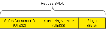
Figure 11 – RequestSPDU
Figure 12 shows the structure of a ResponseSPDU which originates at the SafetyProvider and contains the SafetyData (1 to 1 500 octets), an additional 25 octet safety code (STrailer) and the NonSafetyData. See 7.2.1.5 to 7.2.1.11 for details. See 6.2.3.4 for details on the ResponseSPDUDataType definition.
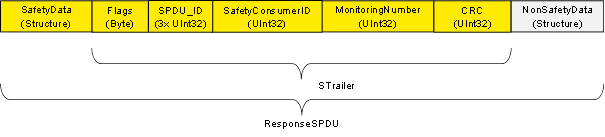
Figure 12 – ResponseSPDU
NOTE 2 To avoid spurious trips, the ResponseSPDU is transmitted in an atomic (consistent) way from the OPC UA Platform Interface of the SafetyProvider to the OPC UA Platform Interface of the SafetyConsumer. This is the task of the respective OPC UA mapper, see Figure 2.
Identifier of the SafetyConsumer instance, for diagnostic purposes, see 9.1.2.
The SafetyConsumer uses the MNR to detect SPDUs with timeliness errors, e.g. such SPDUs which are continuously repeated by an erroneous network element which stores data. A different MNR is used in every RequestSPDU of a given SafetyConsumer, and a ResponseSPDU will only be accepted if its MNR matches the MNR of the corresponding RequestSPDU.
The checking for correctness of the MNR is only performed by the SafetyConsumer.
[RQ7.1] The flags of the SafetyConsumer (RequestSPDU.Flags) shall be used as shown in 6.2.3.1.
[RQ7.2] SafetyData shall contain the safety-related application data transmitted from the SafetyProvider to the SafetyConsumer. It is comprised of a single or multiple basic OPC UA Variables (see 6.2.5). For the sake of reducing distinctions of cases, SafetyData shall always be a Structure, even if it comprised of only a single basic OPC UA Variable.
For the calculation of the CRC signature, the order in which this data is processed by the calculation is important. SafetyProvider and SafetyConsumer shall agree upon the number, type and order of application data transmitted in SafetyData. The sequence of SafetyData is fixed.
SafetyData may contain qualifiers for a fine-grained activation of fail-safe substitute values. For valid process values, the respective qualifiers are set to 1 (good), whereas the value 0 (bad) is used for invalid values. Invalid process values are replaced by fail-safe substitute values in the SafetyConsumer’s safety application. See 6.3.6.
[RQ7.3] The flags of the SafetyProvider (ResponseSPDU.Flags) shall be used as shown in 6.2.3.2.
[RQ7.4] Flags in the ResponseSPDU.Flags which are reserved for future use shall be set to zero by the SafetyProvider and shall not be evaluated by the SafetyConsumer.
This field is used by the SafetyConsumer to check whether the ResponseSPDU is coming from the correct SafetyProvider. For details, see 7.2.3.1.
[RQ7.5] The SafetyConsumerID in the ResponseSPDU shall be a copy of the SafetyConsumerID received in the corresponding RequestSPDU. See 7.2.3.1.
[RQ7.6] The MonitoringNumber in the ResponseSPDU shall be a copy of the MonitoringNumber received in the corresponding RequestSPDU. See 7.2.3.1.
NOTE The SafetyConsumer uses the ResponseSPDU.MonitoringNumber to detect SPDUs received with timeliness error, e.g. SPDUs which are continuously repeated by an erroneous network element which stores data. A different MonitoringNumber is used in every RequestSPDU of a given SafetyConsumer, and a ResponseSPDU will only be accepted if its MonitoringNumber matches the MonitoringNumber in the corresponding RequestSPDU.
[RQ7.7] The ResponseSPDU CRC shall be used to detect data corruption. See 7.2.3.6 on how it is calculated in the SafetyProvider and how it is checked in the SafetyConsumer.
[RQ7.8] This structure shall be used to transmit NonSafetyData values (e.g. diagnostic information) together with SafetyData consistently. NonSafetyData is not CRC-protected and can stem from an unsafe source.
[RQ7.9] When presented to the safety application (e.g. at an output of the SafetyConsumer), non-safety values shall clearly be indicated as “non-safety” by an appropriate vendor-specific mechanism (e.g. by using a different colour).
To avoid possible problems with empty structures, the dummy structure NonSafetyDataPlaceholder shall be used when no NonSafetyData is used (see requirement RQ6.8).
The two SCL services SafetyProvider and SafetyConsumer are specified using state diagrams.
Figure 13 and Figure 14 show sequences of requests and responses with SafetyData for this document using OPC UA Client/Server and PubSub communication mechanisms, respectively. The figures show selected scenarios only and are therefore informative.
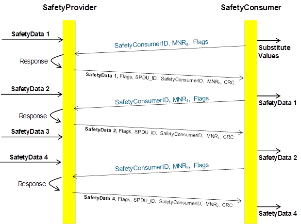
Figure 13 (informative) – Sequence diagram for requests and responses (Client/Server)
[RQ7.10] In the case of Client/Server communication, a SafetyConsumer’s OPC UA Mapper may call a SafetyProvider (either the state machine implementation itself or the SafetyProvider’s OPC UA Mapper) with an identical RequestSPDU multiple times in a row. In that case, the SafetyProvider (state machine or OPC UA Mapper) shall answer all requests. The returned ResponseSPDUs may contain different values (e.g. currently available process values) or contain the initially returned values.
[RQ7.11] For each SafetyProvider, the implemented choice of behaviour according to RQ7.10 (i.e. whether currently available process values or initially returned values will be used) shall be documented in the corresponding safety manual.
NOTE 2 Since a SafetyConsumer checks for changed MNRs in ResponseSPDUs (see SafetyConsumer state S14_WaitForChangedSPDU in Table 34 and transition T17 in Table 35), and therefore will use only the first evaluated ResponseSPDU for a given MNR and all further ResponseSPDUs with the same MNR will be ignored.
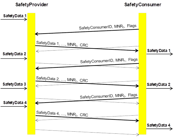
NOTE The bold arrows represent communication with new data values, whereas dashed arrows contain repeated data values.
Figure 14 (informative) – Sequence diagram for requests and responses (PubSub)
NOTE 3 The state machines according to this document do not contain any retry-mechanisms to increase fault tolerance. In contrast, it is assumed that retry is already handled within the OPC UA stack (e.g. when using Client/Server, or by choosing a higher update rate for PubSub). The dashed lines therefore are not part of this document, but rather symbolize the repeated sending of data implemented in the OPC UA stack.
The SafetyConsumerTimeout is the watchdog time checked in the SafetyConsumer. The watchdog is restarted immediately before a new RequestSPDU is generated (transitions T14 and T28 of the SafetyConsumer in Table 35). If an appropriate ResponseSPDU is received in time, and the checks for data integrity, authenticity, and timeliness are all valid, the timer will not expire before it is restarted.
Otherwise, the watchdog timer expires, and the SafetyConsumer triggers a safe reaction. To duly check its timer, the SafetyConsumer is executed cyclically, with period ConsumerCycleTime. ConsumerCycleTime is expected to be smaller than SafetyConsumerTimeout.
The ConsumerCycleTime is the maximum time for the cyclic update of the SafetyConsumer. It is the timeframe from one execution of the SafetyConsumer to the next execution of the SafetyConsumer. The implementation of the monitoring of the ConsumerCycleTime and the reaction in case of exceeding the ConsumerCycleTime are not part of this document; these are vendor-specific.
[RQ7.12] The ConsumerCycleTime shall be monitored in a safety-related way.
[RQ7.26] A change of the SafetyConsumerTimeout parameter value shall take immediate effect on the ConsumerTimer.
In case it is necessary to ensure that a given SafetyData (e.g. a safety demand or a command value) that originates in the SafetyProvider’s safety application is being received by a SafetyConsumer and forwarded to the SafetyConsumer’s safety application, i.e. if no SafetyData in a series of SafetyData is to be missed, the following two cases shall be considered.
In case A, repeated identical RequestSPDUs are being answered by the SafetyProvider with ResponseSPDUs which contain the initially returned value. This is the case for PubSub communication and is a choice for Client/Server communication, see RQ7.11. In this case, the SafetyProvider’s safety application shall provide the respective SafetyData at the SafetyProvider’s SAPI until at least one change of the MNR is detected.
In case B, repeated identical RequestSPDUs are being answered by the SafetyProvider with the currently available SafetyData. This is a choice for Client/Server communication, see RQ7.11. In this case, the SafetyProvider’s safety application shall provide the respective SafetyData at the SafetyProvider’s SAPI until at least two changes of the MNR have been detected.
Figure 15 and Figure 16 show examples justifying case B by depicting two sequences of ResponseSPDUs as sent by a SafetyProvider. Due to the cycles of SafetyProvider and SafetyConsumer not being synchronized, a SafetyConsumer can evaluate any one of a given number of ResponseSPDUs for a given RequestSPDU.
In the examples, the SafetyData is made up of two components: the “respective safety data”, i.e. a safety demand that is not to be missed (one of the values “A”, “B” or “C”) and non-demand numerical measurement values for which it does not matter whether some are not received by the SafetyConsumer.
The worst-case time to make sure that the respective safety data from the SafetyProvider is made available to the SafetyConsumer is two times the SafetyConsumerTimeout. This worst-case time occurs when the two transmissions of a RequestSPDU and its corresponding ResponseSPDU, which are necessary according to the descriptions above, each take a time of just slightly under one SafetyConsumerTimeout.
If the SafetyConsumer’s SafetyConsumerTimeout is known at the SafetyProvider, the SafetyProvider may alternatively provide the respective safety data for at least two times the SafetyConsumerTimeout to ensure that the respective safety data reaches the SafetyConsumer.
Since NonSafetyData is consistently transmitted with SafetyData, the same considerations apply for NonSafetyData.
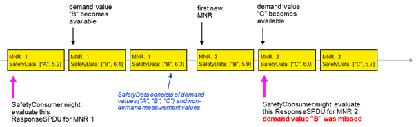
Figure 15 – Duration of demand example for missed demand value in case of currently available SafetyData not being provided until second change of MNR
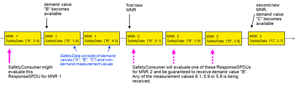
Figure 16 – Duration of demand example for received demand value in case of currently available SafetyData being provided
[RQ7.13] Figure 17 shows a simplified representation of the state diagram of the SafetyProvider. The exact behaviour is described in Table 30, Table 31, and Table 32. The SafetyProvider shall implement that behaviour. It is not required to literally follow the entries given in the tables, if the externally observable behaviour does not change.
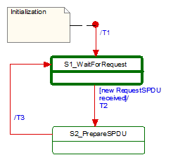
Figure 17 – Simplified representation of the state diagram for the SafetyProvider
Table 29 shows the symbols used for state machines.
Table 29 – Symbols used for state machines
|
Type |
Description |
|
|
|
Activity state |
Within these interruptible activity states the SafetyProvider waits for new input. |
|
|
Action state |
Within these non-interruptible action states events like new requests are deferred until the next activity state is reached, see [1][1]. |
The transitions are fired in case of an event. “Event” in this context means either a Method call in the case of Client/Server communication or the detection of a changed RequestSPDU by the OPC UA Mapper in the case of PubSub communication.
In case of several possible transitions, so-called guard conditions (refer to […] in UML diagrams) define which transition to fire.
The diagram consists of activity and action states. Activity states are surrounded by bold lines, action states are surrounded by thin lines. While activity states can be interruptible by new events, action states are not. External events occurring while the state machine is in an action state, are deferred until the next activity state is reached.
NOTE The details on how to implement activity states and action states are vendor-specific. Typically, in a real-time system the task performing the SafetyProvider or SafetyConsumer state machine is executed cyclically (see 6.3.5). Whenever the task is woken up by the scheduler of the operating system while it is in an action state, it executes action states until its time slice is used up, or an activity state is reached. Whenever a task being in an activity state is woken up, it checks for input. If no new input is available, it immediately returns to the sleep state without changing state.
If input is available, it starts executing action states until its time-slice is up or until the next activity state is reached.
Table 30 shows the internal items of a SafetyProvider instance.
Table 30 – SafetyProvider instance internal items
|
Internal items |
Type |
Definition |
|
RequestSPDU_i |
Variable |
Local memory for RequestSPDU (required to react on changes). |
|
SPDU_ID_1_i |
UInt32 |
Local variable to store SPDU_ID_1. |
|
SPDU_ID_2_i |
UInt32 |
Local variable to store SPDU_ID_2. |
|
SPDU_ID_3_i |
UInt32 |
Local variable to store SPDU_ID_3. |
|
BaseID_i |
Guid |
Local variable containing the BaseID (taken either from the SPI or SAPI). |
|
ProviderID_i |
UInt32 |
Local variable containing the ProviderID (taken either from the SPI or SAPI). |
|
<Get RequestSPDU> |
Macro |
Instruction to take the whole RequestSPDU from the OPC UA Mapper. |
|
<Set ResponseSPDU> |
Macro |
Instruction to transfer the whole ResponseSPDU to the OPC UA Mapper. |
|
<Calc SPDU_ID_i> |
Macro |
const uint32 SafetyProviderLevel_ID:= … // see 7.2.3.4 If(SAPI.SafetyBaseID
== 0) then Endif Endif SPDU_ID_1_i:= BaseID_i (octets 0…3) SPDU_ID_2_i:= BaseID_i (octets 4…7) SPDU_ID_3_i:= BaseID_i (octets 8…11) // see 7.2.3.2 for clarification |
|
<build ResponseSPDU> |
Macro |
Take the MNR and the SafetyConsumerID of the received RequestSPDU. Add the SPDU_ID_1_i, SPDU_ID_2_i, SPDU_ID_3_i, Flags, the SafetyData and the NonSafetyData, as well as the calculated CRC. See 7.2.3.1 |
Table 31 shows the states of a SafetyProvider instance. The SafetyProvider does not check for correct configuration. It will reply to requests even if it is incorrectly configured (e.g. its SafetyProviderID is zero). However, SafetyConsumers will never try to communicate with SafetyProviders having incorrect parameters, see Transitions T13 and T27 in Table 35 and the macro <ParametersOK?> in Table 33.
Table 31 – States of SafetyProvider instance
|
State name |
State description |
|
Initialization |
// Initial state SAPI.SafetyData:= 0 SAPI.NonSafetyData:= 0 SAPI.OperatorAckRequested:= 0 RequestSPDU_i:= 0 |
|
S1_WaitForRequest |
// waiting on next RequestSPDU from SafetyConsumer <Get RequestSPDU> |
|
S2_PrepareSPDU |
ResponseSPDU.Flags.ActivateFSV:=
SAPI.ActivateFSV <Calc SPDU_ID_i> <build ResponseSPDU> // see 7.2.3.1 |
Table 32 shows the transitions of the SafetyProvider.
Table 32 – SafetyProvider transitions
|
Transition |
Source state |
Target state |
Guard condition |
Activity |
|
T1 |
Init |
S1 |
|
|
|
T2 |
S1 |
S2 |
// RequestSPDU received1 - |
// Process request RequestSPDU_i:= RequestSPDU SAPI.MonitoringNumber:= RequestSPDU.MonitoringNumber SAPI.SafetyConsumerID:= RequestSPDU.SafetyConsumerID SAPI.OperatorAckRequested:= RequestSPDU.Flags.OperatorAckRequested |
|
T3 |
S2 |
S1 |
// SPDU is prepared - |
<Set ResponseSPDU> |
|
1 See the preceding explanation in 7.2.2.4 of what constitutes events which trigger this transition. |
||||
[RQ7.14] Figure 18 shows a simplified representation of the state diagram of the SafetyConsumer. The exact behaviour is described in Table 33, Table 34, and Table 35. The SafetyConsumer shall implement this behaviour. It is not required to literally follow the entries given in the tables, if the externally observable behaviour does not change.
To avoid unnecessary spurious trips requiring operator acknowledgment, it is recommended that a SafetyConsumer is started after an OPC UA connection to a running SafetyProvider has been established, or that the setting of input SAPI.Enable to “1” is delayed until the SafetyProvider is running.
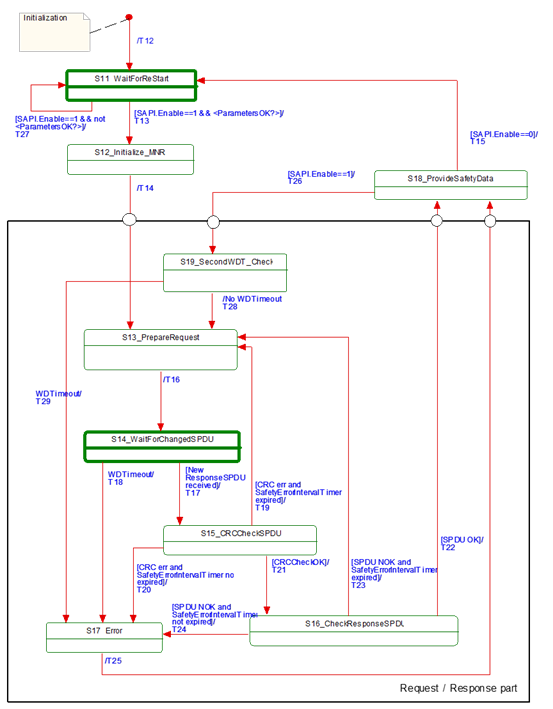
Figure 18 – Principle state diagram for SafetyConsumer
Table 33 shows the internal items of a SafetyConsumer. A macro is a shorthand representation for operations described in the according definition.
Table 33 – SafetyConsumer internal items
|
Internal items |
Type |
Definition |
|
|
Constants |
|
|
|
|
MNR_min:= 0x100 |
UInt32 |
// 0x100 is the start value for MNR, also used after wrap-around // The values 0…0xFF are reserved for future use |
|
|
Variables |
|
|
|
|
FaultReqOA_i |
Boolean |
Local memory for errors which request operator acknowledgment |
|
|
OperatorAckConsumerAllowed_i |
Boolean |
Auxiliary flag indicating that operator acknowledgment is allowed. It is true if the input SAPI.OperatorAckConsumer has been ‘false’ since FaultReqOA_i was set |
|
|
MNR_i |
UInt32 |
Local MonitoringNumber (MNR) |
|
|
prevMNR_i |
UInt32 |
Local memory for previous MNR |
|
|
ConsumerID_i |
UInt32 |
Local memory for SafetyConsumerID in use |
|
|
CRCCheck_i |
Boolean |
Local variable used to store the result of the CRC check |
|
|
SPDUCheck_i |
Boolean |
Local variable used to store the result of the additional SPDU checks |
|
|
SPDU_ID_1_i |
UInt32 |
Local variable to store the expected SPDU_ID_1 |
|
|
SPDU_ID_2_i |
UInt32 |
Local variable to store the expected SPDU_ID_2 |
|
|
SPDU_ID_3_i |
UInt32 |
Local variable to store the expected SPDU_ID_3 |
|
|
SPI_SafetyConsumerID_i |
UInt32 |
Local variable to store the parameter SafetyConsumerID |
|
|
SPI_SafetyProviderID_i |
UInt32 |
Local variable to store the parameter SafetyProviderID |
|
|
SPI_SafetyBaseID_i |
UInt128 |
Local variable to store the parameter SafetyBaseID |
|
|
SPI_SafetyStructureSignature_i |
UInt32 |
Local variable to store the parameter SafetyStructureSignature |
|
|
SPI_SafetyOperatorAckNecessary_i |
Boolean |
Local variable to store the parameter SafetyOperatorAckNecessary |
|
|
SPI_SafetyErrorIntervalLimit_i |
UInt16 |
Local variable to store the parameter SafetyErrorIntervalLimit |
|
|
Boolean |
Local variable used to support re-synchronization of MNR after detected error |
||
|
Timers |
|
|
|
|
ConsumerTimer |
Timer |
This timer is used to check whether the next valid ResponseSPDU has arrived on time. It is initialized using the parameter SPI.SafetyConsumerTimeout. NOTE As opposed to other parameters, a modification of the parameter value SafetyConsumerTimeout takes effect immediately, i.e. not only when state S11 is visited, see RQ7.26. |
|
|
ErrorIntervalTimer |
Timer |
This timer is used to check the elapsed time between errors. If the elapsed time between two consecutive errors is smaller than the value SafetyErrorIntervalLimit, FSV will be activated. Otherwise, the ResponseSPDU is discarded and the SafetyConsumer waits for the next ResponseSPDU. This timer is initialized using the local variable SPI_SafetyErrorIntervalLimit_i. See Table 26, 6.3.4.3, and 9.4 for more information. NOTE The local variable SPI_SafetyErrorIntervalLimit_i is not to be confused with the parameter SPI.SafetyErrorIntervalLimit. The local variable is copied from the parameter in state S11 (restart). Hence, if the parameter value changes during runtime, the new value will only be used after the connection has been restarted. |
|
|
Macros <...><...> |
|
|
|
|
<risingEdge x> |
Macro |
// detection of a rising edge: If x==true &&
tmp==false tmp:= x |
|
|
<Get ResponseSPDU> |
Macro |
Instruction to take the whole ResponseSPDU from the OPC UA Mapper. |
|
|
<Use FSV> |
Macro |
SAPI.SafetyData is set to binary 0 If
[<ConsumerTimer expired || SAPI.Enable==0 ?>] Else Endif SAPI.FSV_Activated:= 1 RequestSPDU.Flags.FSV_Activated:= 1 NOTE 1 If a safety application prefers fail-safe values other than binary 0, this can be implemented in the safety application by querying SAPI.FSV_Activated. NOTE 2 The NonSafetyData is always updated if data is available. In case of a timeout, no data is available, which is indicated using binary zero. If it is necessary for an application to distinguish between “no data available” and “binary zero received”, it can add a Boolean variable to the NonSafetyData. This value is set to ”1” during normal operation, and to ”0” for indicating that no data is available. |
|
|
<Use PV> |
Macro |
SAPI.SafetyData is set to ResponseSPDU.SafetyData SAPI.NonSafetyData is set to ResponseSPDU.NonSafetyData SAPI.FSV_Activated:= 0 RequestSPDU.Flags.FSV_Activated:= 0 RequestSPDU.Flags.CommunicationError:= 0 |
|
|
<Set RequestSPDU> |
Macro |
Instruction to transfer the whole RequestSPDU to the OPC UA Mapper. |
|
|
<(Re)Start ConsumerTimer> |
Macro |
Restarts the ConsumerTimer. |
|
|
<(Re)Start ErrorIntervalTimer> |
Macro |
Restarts the ErrorIntervalTimer. |
|
|
<ConsumerTimer expired?> |
Macro |
Yields “true” if the timer is running longer than SPI.SafetyConsumerTimeout since last restart, “false” otherwise. |
|
|
<ErrorIntervalTimer expired?> |
Macro |
Yields “true” if the timer is running longer than SPI.SafetyErrorIntervalLimit since last restart, “false” otherwise. |
|
|
<Assign ConsumerID> |
Macro |
If SAPI.SafetyConsumerID != 0 Then ConsumerID_i:= SAPI.SafetyConsumerID Else ConsumerID_i:= SPI_SafetyConsumerID_i Endif |
|
|
<Calc SPDU_ID_i> |
Macro |
uint128 BaseID uint32 ProviderID const uint32 SafetyProviderLevel_ID:= … // see 7.2.3.4 If(SAPI.SafetyBaseID == 0) Then Endif Then Endif SPDU_ID_1_i:= BaseID (octets 0…3) SPDU_ID_2_i:= BaseID (octets 4…7) SPDU_ID_3_i:= BaseID (octets 8…11) // see 7.2.3.2 for clarification |
|
|
<ParametersOK?> |
Macro |
Boolean result:= true If(SAPI.SafetyProviderID
== 0 && SPI_SafetyProviderID_i==0) If(SAPI.SafetyConsumerID
== 0 && SPI_SafetyConsumerID_i==0) If(SPI_SafetyStructureSignature_i==0) yield result |
|
|
<Set Diag(ID, Boolean isPermanent)> |
Macro |
// ID is the identifier for the type of diagnostic
output, see Table 28. If(RequestSPDU.Flags.CommunicationError
== 0) RequestSPDU.Flags.CommunicationError:= isPermanent |
|
|
<ResponseSPDU |
Macro |
Boolean result:= false If MNR_re_sync_i == false Then Then result:= true Else Else If ResponseSPDU.MNR == MNR_i Then result:= true Else Endif yield result |
|
|
<Handle WDTimeout> |
Macro |
<Set Diag(CommErrTO,isPermanent:=true)> If SPI_SafetyOperatorAckNecessary_i
== 1 |
|
|
External event |
|
|
|
|
Restart cycle |
Event |
The external call of SafetyConsumer can be interpreted as event “restart cycle” |
|
Table 34 shows the states of the SafetyConsumer. The SafetyConsumer parameters are accessed only in state S11. In this state, a copy is made, and in all other states and transitions the copied values are used. This ensures that a change of one of these parameters takes effect only when a new safety connection is established. The only exception from this rule is the parameter SafetyConsumerTimeout. A change of this parameter becomes effective immediately (see RQ7.26). If this is not the desired behaviour, i.e. if parameters should be changeable during runtime, this can be accomplished by establishing a second safety connection according to this document with the new parameters, and then switching between these two safety connections at runtime.
Table 34 – SafetyConsumer states
|
State name |
State description |
|
Initialization |
// Initial state of the SafetyConsumer instance. <Use FSV> MNR_re_sync_i:= false |
|
S11_Wait for (Re)Start |
// Safety layer is waiting for (Re)Start // Changes to these parameters are only considered in this state // Exception: a change of SafetyConsumerTimeout is possible during operation // Read parameters from the SPI and store them in local variables: SPI_SafetyConsumerID_i:= SPI.SafetyConsumerID SPI_SafetyProviderID_i:= SPI.SafetyProviderIDConfigured SPI_SafetyBaseID_i:= SPI.SafetyBaseIDConfigured SPI_SafetyStructureSignature_i:= SPI.SafetyStructureSignature SPI_SafetyOperatorAckNecessary_i:= SPI.SafetyOperatorAckNecessary SPI_SafetyErrorIntervalLimit_i:= SPI_SafetyErrorIntervalLimit |
|
S12_initialize MNR |
// Use previous MNR if known MNR_i:= (previous MNR_i if known) or (random MNR) MNR_i:= max(MNR_i, MNR_min)1 |
|
S13_PrepareRequest |
// Build RequestSPDU and send (done in T16) |
|
S14_WaitForChangedSPDU |
// Safety Layer is waiting for next ResponseSPDU from SafetyProvider. // A new ResponseSPDU is characterized by a change in the MNR. |
|
S15_CRCCheckSPDU |
// Check CRC uint32 CRC_calc // see 7.2.3.6 on how to calculate CRC_calc |
|
S16_CheckResponseSPDU |
// Check SafetyConsumerID and SPDU_ID and MNR (see T22, T23, T24) SPDUCheck_i:= |
|
S17_Error |
SAPI.TestModeActivated:= 0 |
|
S18_ProvideSafetyData |
// Provide SafetyData to the application program |
|
S19_SecondWDT_Check |
// Second check of WDTimeout // Prevents restarting of ConsumerTimer if it expired since initial check |
|
1 This ensures that the MNR is greater or equal to MNR_min, in cases the random number generator yielded a smaller value. |
|
Table 35 shows the transitions of the SafetyConsumer.
Table 35 – SafetyConsumer transitions
|
Tran |
Source state |
Target state |
Activity |
|
|
T12 |
Init |
S11 |
- |
|
|
T13 |
S11 |
S12 |
//Start [SAPI.Enable==1 && <ParametersOK?>] |
<(Re)Start
ErrorIntervalTimer> |
|
T14 |
S12 |
S13 |
// MNR initialized |
<(Re)Start ConsumerTimer> <Assign ConsumerID> |
|
T15 |
S18 |
S11 |
// Termination [SAPI.Enable==0] |
<Use FSV> RequestSPDU.Flags.CommunicationError:= 0 // necessary to make sure that no diagnostic // message is lost, see macro <Set Diag ...> // NOTE Depending on its implementation, it could // be necessary to stop the ConsumerTimer here. |
|
T16 |
S13 |
S14 |
// Build RequestSPDU |
prevMNR_i:= MNR_i If MNR_i == 0xFFFFFFFFF MNR_i:= MNR_i
+ 1 RequestSPDU.MonitoringNumber:= MNR_i <Set RequestSPDU> |
|
T17 |
S14 |
S15 |
// Changed ResponseSPDU <Get ResponseSPDU>2 <ResponseSPDU ready for checks> |
// A changed ResponseSPDU is characterized by a change in the MNR. |
|
T18 |
S14 |
S17 |
// WDTimeout [<ConsumerTimer expired?>] |
|
|
T19 |
S15 |
S13 |
// When CRC err and ErrorIntervalTimer expired |
MNR_re_sync_i:= true <(Re)Start ErrorIntervalTimer> |
|
T20 |
S15 |
S17 |
// When CRC err and ErrorIntervalTimer not expired [(crcCheck_i == 0) && not <ErrorIntervalTimer expired?>] |
<(Re)Start ErrorIntervalTimer> FaultReqOA_i:= 1 |
|
T21 |
S15 |
S16 |
// When CRCCheckOK [crcCheck_i == 1] |
- |
|
T22 |
S16 |
S18 |
// SPDU OK [SPDUCheck_i==true] |
// For clarification, refer to Figure 19; MNR_re_sync_i:= false // indicate OA from provider SAPI.OperatorAckProvider:= ResponseSPDU.Flags.OperatorAckProvider // OA requested due to rising edge at ActivateFSV? If
(<risingEdge ResponseSPDU.Flags.ActivateFSV>&& SPI_SafetyOperatorAckNecessary_i
== true) Endif // Set Flags if OA requested: If
FaultReqOA_i==1 // Wait until OperatorAckConsumer is not active If SAPI.OperatorAckConsumer==0 Then OperatorAckConsumerAllowed_i:= 1 Else //do nothing Endif // Reset Flags after OA: If SAPI.OperatorAckConsumer ==1 && OperatorAckConsumerAllowed_i == 1 Then SAPI.OperatorAckRequested:=
0, RequestSPDU.Flags.OperatorAckRequested:= 0 // do nothing Endif If SAPI.OperatorAckRequested==1
|| ResponseSPDU.Flags.ActivateFSV==1 // Notify safety application that SafetyProvider is in test mode: SAPI.TestModeActivated:= ResponseSPDU.Flags.TestModeActivated |
|
T23 |
S16 |
S13 |
// SPDU NOK and ErrorIntervalTimer
expired |
<(Re)Start ErrorIntervalTimer>, MNR_re_sync_i:= true // Send diagnostic message
according to the If ResponseSPDU.SafetyConsumerID <> ConsumerID_i isPermanent:=false)>3 |
|
T24 |
S16 |
S17 |
// SPDU NOK and ErrorIntervalTimer not expired
|
<(Re)Start ErrorIntervalTimer> If ResponseSPDU.SafetyConsumerID<> ConsumerID_i FaultReqOA_i:= 1 SAPI.OperatorAckRequested:= 0 |
|
T25 |
S17 |
S18 |
// SPDU NOK - |
MNR_re_sync_i:= true |
|
T26 |
S18 |
S19 |
// Restart Cycle [SAPI.Enable==1] |
- |
|
S11 |
S11 |
// Invalid parameters [SAPI.Enable==1 && not <ParametersOK?>] |
<Set Diag(ParametersInvalid, isPermanent:=true)> |
|
|
T28 |
S19 |
S13 |
// No WDTimeout |
<(Re)Start ConsumerTimer> |
|
T29 |
S19 |
S17 |
// WDTimeout [<ConsumerTimer expired?>] |
<Handle WDTimeout> |
|
1 Another event like “Method completion successful” can be used as guard condition of “Changed ResponseSPDU received” as well. 2 SPDUs with all values (incl. CRC signature) being zero shall be ignored, see requirement RQ5.6. 3 See Table 28. |
||||
Figure 19 shows the sequence after the detection of an error requiring operator acknowledge until communication returns to delivering process values again.
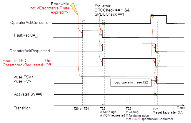
Figure 19 – Sequence diagram for OA
After the error is gone the sequence follows the logic of T22 in Table 35.
[RQ7.15] The ResponseSPDU shall be built by the SafetyProvider by copying RequestSPDU.MonitoringNumber and RequestSPDU.SafetyConsumerID into the ResponseSPDU. In addition, SPDU_ID, Flags, the SafetyData and the NonSafetyData shall be updated. Finally, ResponseSPDU.CRC shall be calculated and appended.
Figure 20 gives an overview over the task of building the ResponseSPDU.
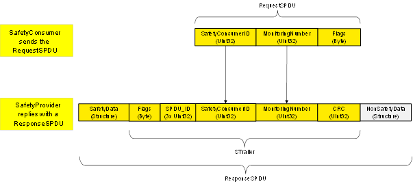
Figure 20 – Overview of task for SafetyProvider
For the ResponseSPDU.Flags, see 7.2.1.6. For the calculation of the SPDU_ID, see 7.2.3.2. For the calculation of the CRC, see 7.2.3.6.
[RQ7.16] SPDU_ID_1, SPDU_ID_2 and SPDU_ID_3 shall be calculated according to Figure 21 and Table 36.
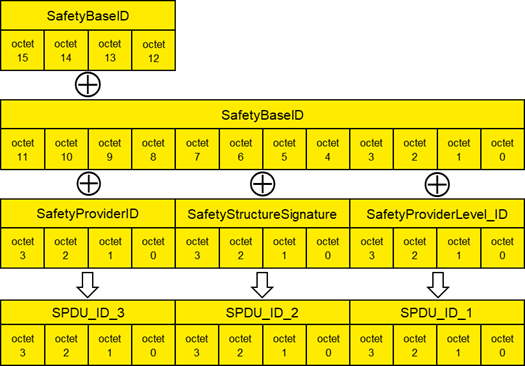
Figure 21 – Calculation of the SPDU_ID
Table 36 – Presentation of the SPDU_ID
|
SPDU_ID_1:= SafetyBaseID (octets 0…3) XOR SafetyProviderLevel_ID (octets 0…3) |
|
SPDU_ID_2:= SafetyBaseID (octets 4…7) XOR SafetyStructureSignature (octets 0…3) |
|
SPDU_ID_3:= SafetyBaseID (octets 8…11) XOR SafetyBaseID (octets 12…15) XOR SafetyProviderID (octets 0…3) |
In case of a mismatch between expected SPDU_ID and actual SPDU_ID, the following rules can be used for diagnostic purposes:
· If all of SPDU_ID_1, SPDU_ID_2, and SPDU_ID_3 differ, there probably is a mismatching SafetyBaseID.
· If SPDU_ID_3 differs, but SPDU_ID_1 and SPDU_ID_2 do not, there is a mismatching SafetyProviderID.
· If SPDU_ID_2 differs, but SPDU_ID_1 and SPDU_ID_3 do not, the structure or identifier of the SafetyData do not match.
· If SPDU_ID_1 differs, but SPDU_ID_2 and SPDU_ID_3 do not, the SafetyProviderLevel does not match.
By these rules, there is a very low probability (<10-9) that a mismatching SafetyBaseID will be misinterpreted. From a practical view, this probability can be ignored.
Figure 22 shows a concrete example of the calculation of SPDU_ID_1, SPDU_ID_2 and SPDU_ID_3. The following input values were chosen for the calculation: SafetyBaseID is the GUID “72962B91-FA75-4AE6-8D28-B404DC7DAF63”, SafetyProviderID has the value 0xE0EA6B40, SafetyStructureSignature has the value 0xDE7329FD and the SafetyProviderLevel_ID is chosen as 0xDEAA9DEE (representing SIL3).
See OPC 10000-6, 5.2.2.6 for details on the encoding of Guids. The octets from the resulting octet stream are used according to Figure 21, i.e. in “reverse order”.
The resulting SPDU_IDs are as follows: SPDU_ID_1 has the value of 0xAC3CB67F, SPDU_ID_2 has the value of 0x9495D388 and SPDU_ID_3 has the value of 0x87F13E11.
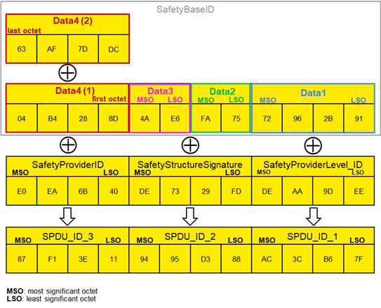
Figure 22 (informative) – Example for the calculation of SPDU_ID_1, SPDU_ID_2 and SPDU_ID_3
The SafetyProviderLevel is the SIL the SafetyProvider implementation (hardware and software) is capable of.
Table 37 – Coding for the SafetyProviderLevel_ID
|
SafetyProviderLevel |
Value of SafetyProviderLevel_ID |
|
SIL1 |
0x11912881 |
[RQ7.17] Exactly one of the values provided in Table 37 shall be used as constant code value for SafetyProviderLevel_ID. The values were chosen in such a way that the hamming distance between them becomes maximal (hamming distance of 21).
[RQ7.18] Measures shall be taken to avoid that a SafetyProvider is erroneously using a code value belonging to a SIL that is higher than the SIL it is capable of. For instance, a SafetyProvider capable of SIL1 to SIL3 should not be able to accidently use the value 0xAB47F33B used for SIL4. One way to achieve this is to avoid that this constant appears in the source code of the SafetyProvider at all.
The SafetyProviderLevel is independent to the SIL capability of the provided SafetyData, see 3.1.2.12.
SafetyStructureSignature is used to check the number, DataTypes, and order of application data transmitted in SafetyData. If the SafetyConsumer is expecting anything different than what the SafetyProvider actually provides, SafetyStructureSignature will differ, allowing the SafetyConsumer to enable fail-safe substitute values.
In addition, the identifier of the Structure DataType (SafetyStructureIdentifier) is also taken into account when calculating SafetyStructureSignature. This ensures that the SafetyProvider and the SafetyConsumer are using the same identifier for the Structure DataType, effectively avoiding any confusion.
For instance, if a SafetyProvider defines a Structure with identifier “vec3D_m” comprising three Floats containing a three-dimensional vector in the metric system, this Structure could not be used by a SafetyConsumer expecting a Structure of DataType “vec3D_in” where the vector components are given in inches, or even at a SafetyConsumer expecting a Structure of DataType “orientation”, containing three Floats to define an orientation using Euler angles.
[RQ7.19] SafetyStructureSignature shall be calculated as a 32 bit CRC signature (polynomial: 0xF4ACFB13, see Clause B.1) over SafetyStructureIdentifier (encoding: UTF-8), SafetyStructureSignatureVersion and the sequence of the DataTypeEncodingIDs. After each DataTypeEncodingID, a 16-bit zero-value (0x0000) shall be inserted. All integers shall be encoded using little endian octet ordering. Data shall be processed in reverse order, see Clause B.1. The value “0” shall not be used as a signature. Instead, the value “1” shall be used in this case.
The terminating zero of SafetyStructureIdentifier shall not be considered when calculating the CRC.
[RQ7.20] SafetyStructureIdentifier may be visible in the OPC UA Information Model for diagnostic purposes but shall not be evaluated by the SafetyConsumer during runtime.
[RQ7.21] For all releases up to Release 2.0 of the specification, the value for SafetyStructureSignatureVersion shall be 0x0001.
SafetyStructureIdentifier,
e.g. “Motörhead” = 0x4d 0x6f 0x74 0xc3 0xb6 0x72 0x68 0x65 0x61 0x64
SafetyStructureSignatureVersion:= 0x0001
1. DataType Int16: (DataTypeEncodingId = 0x0004), // see 6.2.5
2. DataType Boolean: (DataTypeEncodingId = 0x0001),
3. DataType Float: (DataTypeEncodingId =0x000a)
SafetyStructureSignature
=
= CRC32_Backward(0x4d, 0x6f, 0x74, 0xc3, 0xb6, 0x72, 0x68, 0x65, 0x61, 0x64,
0x01,0x00,
0x04,0x00, 0x00,0x00,
0x01,0x00, 0x00,0x00,
0x0A, 0x00, 0x00, 0x00)
= CRC32_Forward(
0x00, 0x00, 0x00, 0x0A,
0x00, 0x00, 0x00, 0x01,
0x00, 0x00, 0x00, 0x04,
0x00,0x01,
0x64, 0x61, 0x65, 0x68, 0x72, 0xb6, 0xc3, 0x74, 0x6f, 0x4d)
= 0xe2e86173
NOTE 1 The insertion of 0x0000 values after each DataTypeEncodingID allows for introducing arrays in later versions of this document.
NOTE 2 SafetyStructureSignatureVersion is the version of the procedure used to calculate the signature, as defined in requirement RQ7.19. If future releases of this document define an alternative procedure, they will indicate this by using a different version number.
OPC 10000-3, 5.8.2 defines different categories of DataTypes. Regarding the DataTypeEncodingID which is to be used within the SafetyStructureSignature, the following holds:
· For Built-in DataTypes, the ID from Table 1 of OPC 10000-6 is used as DataTypeEncodingID.
· For Simple DataTypes, the DataTypeEncodingID of the Built-in DataType from which they are derived is used.
· As of now, Structured DataTypes (including OptionSets) shall not be used within SafetyData. Arrays are not supported. Instead, multiple variables of the same type are used.
· Enumeration DataTypes are encoded on the wire as Int32 and therefore shall use the DataTypeEncodingID of the Int32 Built-in DataType.
The SafetyProvider calculates the CRC signature (ResponseSPDU.CRC) and sends it to the SafetyConsumer as part of the ResponseSPDU. This enables the SafetyConsumer to check the correctness of the ResponseSPDU including the SafetyData, flags, MNR, SafetyConsumerID and SPDU_ID by recalculating the CRC signature (CRC_calc).
[RQ7.22] The generator polynomial 0xF4ACFB13 shall be used for the 32-Bit CRC signature.
[RQ7.23] If SafetyData is longer than one octet (e.g. if it is of DataType UInt16, Int16 or Float), it shall be decoded and encoded using little endian order in which the least significant octet appears first in the incremental memory address stream.
[RQ7.24] The calculation sequence shall begin with the highest memory address (n) of the STrailer counting back to the lowest memory address (0) and then include also the SafetyData beginning with the highest memory address.
Figure 23 shows the calculation sequence of a ResponseSPDU CRC on a little-endian machine, using an example SafetyData with the following fields:
Int32 var1
UInt32 var2
UInt16 var3
Int16 var4
Boolean var5
For the example given above, the STrailer (without CRC) and SafetyData have a combined length of 34 octets (16 octets STrailer without CRC, 12 octets of SafetyData). The calculation of ResponseSPDU.CRC (SafetyProvider) or CRC_calc (SafetyConsumer) is done in reverse order, from bottom to top. In the example shown in Figure 23, CRC calculation starts at octet index 33 (most significant octet of the MNR) and ends at octet index 0.
NOTE The reverse order ensures that the effectiveness of the CRC mechanism remains independent of any CRCs used within the underlying OPC UA channel, even if it would coincidentally use the same CRC polynomial.
Figure 23 – Calculation of the CRC (on little-endian machines, CRC32_Backward)
An alternative way to calculate the CRC (particularly useful on big-endian machines) is shown in Figure 24. Here, the individual elements of the ResponseSPDU are already arranged in memory in reversed order, and CRC calculation is executed from octet 0 to octet 33.
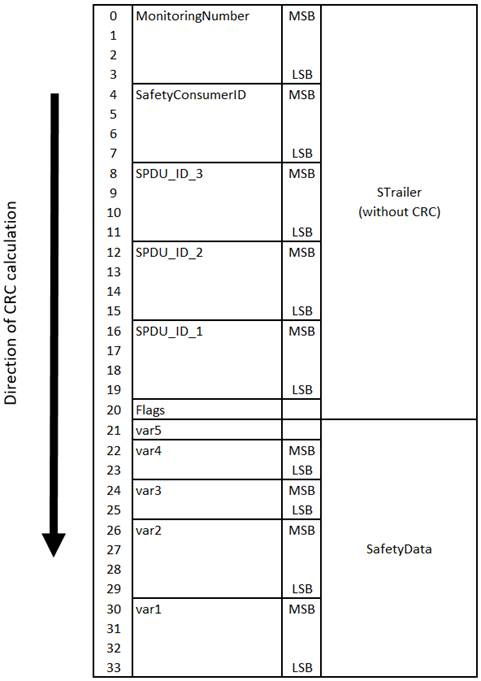
Figure 24 – Calculation of the CRC (on big-endian machines, CRC32_Forward)
[RQ7.25] On the SafetyConsumer, CRC_calc shall be calculated using data received in the ResponseSPDU, and not from expected values.
This chapter gives details about the management of the safety communication layer.
For cyclic communication, the part of the safety function response time attributable to a safety communication according to this document (SFRTOPCSafety) is specified in Formula (1).
Calculation of safety function response time part of OPC UA safety
|
|
SFRTOPCSafety <= 2
× SafetyConsumerTimeout |
(1) |
where
SFRTOPCSafety: Part of the safety function response time attributable to the safety communication according to this document.
SafetyConsumerTimeout: Watchdog timer running in the SafetyConsumer. It is started immediately before a new RequestSPDU is sent (T14 or T28). If the timer runs out a timeout error is triggered (T18 or T29).
ConsumerCycleTime: The maximum time for the cyclic execution of the SafetyConsumer, see 7.2.2.2.
NOTE 1 Formula (1) only addresses the part of the SFRT attributable to OPC UA Safety. The overall SFRT also depends on the implementation of the devices the SafetyProvider and SafetyConsumer are running on. Details on how these fractions of the SFRT are calculated are vendor-specific.
If multiple safety connections according to this document are used within a safety function in series, their respective attributions to the SFRT shall be summed up.
Figure 25 – Overview of delay times and watchdogs
Formula (1) is justified by Figure 25 and the following explanation:
1) The SafetyConsumer sends a RequestSPDU. At about the same time, a dangerous event occurs at the SafetyProvider, demanding the safety function to trigger.
2) However, in the worst case, the RequestSPDU is processed at the SafetyProvider just before the dangerous event becomes known.
3) Hence, the ResponseSPDU does not yet contain any information about the dangerous event.
4) In the worst case, the ResponseSPDU is processed in the SafetyConsumer just before the SafetyConsumerTimeout expires.
5) An error leads to a loss or unacceptable delay of either the RequestSPDU or the ResponseSPDU.
6) Hence, the SafetyConsumerTimeout expires.
7) In the worst case, the timer expires immediately after it was checked. Hence, it takes another cycle of the SafetyConsumer to detect the error.
SafetyConsumerTimeout is a parameter of the SafetyConsumer. ConsumerCycleTime depends on the maximum sample time of the SafetyConsumer application. At commissioning, the integrator should be advised to design it shorter than a quarter of the target SFRTOPCSafety. If the watchdog time SafetyConsumerTimeout is too small, spurious trips can occur. To avoid this, SafetyConsumerTimeout should be chosen as shown in Formula (2).
Selection of the watchdog parameter SafetyConsumerTimeout
|
|
SafetyConsumerTimeout >= T_CD_RequestSPDU
+ |
(2) |
where
T_CD_RequestSPDU: The worst-case communication delay for the RequestSPDU.
NOTE 2 T_CD_RequestSPDU can include the occurrence of dropped messages in the standard transmission system.
T_CD_ResponseSPDU: The worst-case communication delay for the ResponseSPDU.
NOTE 3 T_CD_ResponseSPDU can include the occurrence of dropped messages in the standard transmission system.
SafetyProviderDelay: The worst-case SafetyProvider delay.
Typically, one scan time period of the SafetyProvider.
SafetyConsumerDelay: The worst-case SafetyConsumer delay.
Typically, one scan time period of the SafetyConsumer.
NOTE 4 The reason why SafetyConsumerDelay is part of the summation is that it can take one cycle after the asynchronous reception of the ResponseSPDU to execute the checks.
[RQ8.1] To support the calculation of SafetyConsumerTimeout the SafetyProvider shall provide the SafetyProviderDelay as a Variable in the OPC UA Information Model, see Table 12.
Vendors may provide their individual adapted calculation method if necessary.
The pair of SafetyProviderID and SafetyBaseID is used by the SafetyConsumer to check the authenticity of the ResponseSPDU. SafetyProviderID and SafetyBaseID are usually assigned during engineering or during commissioning. It is in the responsibility of the end user or OEM to assign unique SafetyProviderID to individual SafetyProviders whenever this is reasonable possible. For instance, a machine builder should assign unique SafetyProviderIDs within a single machine containing multiple devices which run implementations of this document.
As the effort for the administration of unique SafetyProviderIDs will reach its limits when the system becomes large, this document uses the SafetyBaseID for cases where guaranteeing unique SafetyProviderIDs is not possible.
A SafetyBaseID is a universal unique identifier version4 (UUIDv4, also called globally unique identifier (GUID)), as described in ISO/IEC 9834-8:2014, Clause 15.It is a 128-bit number where at least 96 bits were chosen randomly. The probability that two randomly generated UUIDs are identical is extremely low (2-96 < 10-28), and can therefore be neglected, even when considering applications with a safety integrity level of 4.
When implementing or using a generator for the UUIDs, it shall be ensured that each possible value is generated with equal probability (discrete uniform distribution), and that any two values are independent from each other. When a pseudo random number generator (PNRG) is used, it is ‘seeded’ with a random source having enough collision entropy (e.g. seeds of at least 128 bits that are uniformly distributed, too; and all seeds being pairwise independent from each other).
Most commercial systems offer random number generators for applications within a cryptographic context. These applications pose even harder requirements on the quality of random numbers than the ones mentioned above. Hence, cryptographically strong random number generators are applicable to this document as well. See References [2] to [5], as well as OPC 10000-2, for detailed information.
Table 38 shows implementations of cryptographically strong random number-generators that can be used to calculate the random part of the UUIDv4:
Table 38 – Examples for cryptographically strong random number generators
|
Environment |
Function |
|
Microsoft® Windows® |
BCryptGenRandom |
|
Unix®-like OS |
Read from the file: |
|
.NET® |
RandomNumberGenerator |
|
JavaScript® |
Crypto.getRandomValues() |
|
Java® |
java.security.SecureRandom |
|
Python® |
os.urandom(size) |
While being evaluated from a security point of view, probably none of these implementations has been validated with safety in mind. Therefore, there is a remaining risk that these implementations are subject to systematic implementation errors which could decrease the effectiveness of these random numbers. To overcome this problem, the output of the random number generator is not used directly, but a SHA256-hash is calculated over (1) the generator’s output, (2) a timestamp (wall-clock-time or persistent logical clock) and (3) a unique domain name. Any bits of the SHA256-hash can then be used to construct the random parts of the UUIDv4.
[RQ9.1] The parameters SafetyBaseID and SafetyProviderID shall be stored in a non-volatile, i.e. persistent, way.
The SafetyConsumerID allows for discrimination between RequestSPDUs and ResponseSPDUs belonging to different SafetyConsumers. It is mainly used for diagnostic purposes, such as detecting unintentional concurrent access of a single SafetyProvider by multiple SafetyConsumers. Safety-related communication errors which are detected by checking the SafetyConsumerID would also be detected by other mechanisms, including the MNR, the SafetyProviderID, and the SafetyConsumerTimeout.
From a safety point of view, there are no qualitative requirements regarding the generation or administration of the SafetyConsumerID. It may be assigned during engineering, commissioning, at startup, and may even change during runtime. It is not required to check for uniqueness of SafetyConsumerIDs.
However, assigning identical SafetyConsumerIDs to multiple consumers is not recommended because fault localization can become more difficult.
The MNR is used to discriminate messages stemming from the same SafetyProvider and is therefore used to detect timeliness errors such as outdated messages, messages received out-of-order, or streams of messages erroneously repeated by a network storing element (e.g. a router).
To be effective, the set of used MNR values shall not be restricted to a small set. This could happen for connections which are restarted frequently, and which start counting from the same MNR value each time.
There are at least two ways to address this potential problem:
Option 1: [RQ9.2a] Whenever the connection is terminated, the current value of the MNR shall be safely stored within non-volatile memory of the SafetyConsumer. After restart, the previously stored MNR is used for initialization of the MNR (i.e. in state S12 of the SafetyConsumer state machine).
Option 2: [RQ9.2b] Whenever the SafetyConsumer is restarted (i.e. in state S12 of the SafetyConsumer state machine), the MNR is initialized with a 32-bit random number.
Either requirement RQ9.2a or requirement RQ9.2b, or an equivalent solution shall be fulfilled.
Following IEC 61784-3, this document detects all communication errors which can possibly occur in the underlying standard transmission system, including the OPC UA stack. If an error is detected, the erroneous data is discarded. Moreover, this document is designed in such a way that a safety function becomes practically unusable if the failure rate in the underlying, standard transmission system is higher than one error per safety error interval limit (6, 60, or 600 minutes), depending on the desired SIL of the safety function (see Table 26 and Table 39).
Thus, for operational safety functions a failure rate of 0,1 h-1, 1 h-1, or 10 h-1 can be assumed for communication errors occurring in the OPC UA stack. In order to obtain the communication’s contribution to the PFH value of the safety function, this value has to be multiplied by the so-called conditional residual error probability Pre,cond. For the CRC mechanism used in this document, it holds:
Pre,cond ≤ 4,0 × 10⁻¹⁰
This leads to the PFH and PFD values shown in Table 39.
The value 4,0 × 10⁻¹⁰ was justified by extensive numerical evaluation of the 32-bit CRC generator polynomial in use (0xF4ACFB13). The results of this evaluation, executed for all relevant data lengths and all relevant values for the bit error probability p up to p = 0,5, is shown in Figure 26. As can be seen, Pre,cond never exceeds the value 4,0 × 10⁻¹⁰.
Figure 26 – Conditional residual error probability of the CRC check
An explanation that it is indeed necessary to calculate Pre,cond for all data lengths and all relevant values of p can be found in Figure 27. For the data lengths shown in this figure, Pre,cond exceeds the desired value by several orders of magnitudes. The maximum value of Pre,cond is not obtained when p becomes maximal.
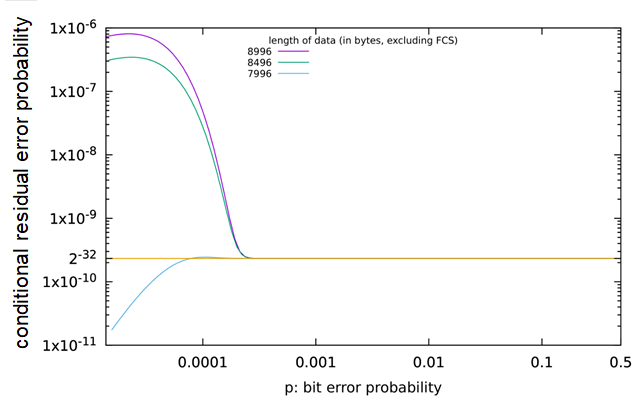
Figure 27 – Counter example: data lengths not supported by OPC Safety
Generally:
· Number of retries in the underlying standard transmission system :
No restrictions
· CRC polynomials used inside the underlying
standard transmission system(e.g. Ethernet, TCP, …):
No restrictions
· Message storing elements:
No restrictions; any number of message storing elements is permitted
· Size of SafetyData within one ResponseSPDU:
≤ 1 500 octets
Even for safety functions that do not require manual operator acknowledgment for restart, manual operator acknowledgment is mandatory whenever the SafetyConsumer has detected certain types of errors and indicates this using OperatorAckRequested. Hence, operator acknowledgment is expected to be implemented by the safety application whenever OPC UA Safety is used. For details, see 6.3.4.3 and Clause B.2.
The PFH value of a logical safety communication link according to this document depends on the parameter of SafetyErrorIntervalLimit (see Table 26) of the link’s SafetyConsumer. Whenever the SafetyConsumer detects a mismatch of the SafetyConsumerID, SPDU_ID, MNR or CRC, it will only continue operating if the last occurrence of such an error happened more than SafetyErrorIntervalLimit time units ago. Otherwise, it will make a transition to fail-safe values, which can only be left by manual operator acknowledgment, see 6.3.4.3.
This directly limits the rate of detected errors, and indirectly limits the rate of undetected (residual) errors.
See Table 39 for numeric PFH and PFD values.
Table 39 – The total residual error rate for the safety communication channel
|
SafetyErrorIntervalLimit |
Allowed for SIL range |
Total residual error rate for one logical connection of the safety function (PFH) |
Total residual error probability for one logical connection of the safety function, for a mission time of 20 years (PFDavg) |
|
6 min |
Up to SIL2 |
< 4,0 × 10⁻⁹ / h |
< 1,0 × 10⁻⁶ |
|
60 min |
Up to SIL3 |
< 4,0 × 10⁻¹⁰ / h |
< 2,5 × 10⁻⁷ |
|
600 min |
Up to SIL4 |
< 4,0 × 10⁻¹¹ / h |
< 8,0 × 10⁻⁸ |
The parameter SafetyErrorIntervalLimit affects either the PFH or the PFD, or both of only the safety communication channel. There is no effect on the PFH and PFD values of the components the SafetyProviders and SafetyConsumers are running on. The requirements for the implementation of these components are specified in the IEC 61508 series.
[RQ9.3] According to IEC 61508-2, the suppliers of equipment implementing an implementation of this document shall provide a safety manual. The instructions, information and parameters of Table 40 shall be included in that safety manual unless they are not relevant for a specific device.
Table 40 – Information to be included in the safety manual
|
|
Item |
Instruction or parameter |
Remark |
|
1 |
Safety handling |
Instructions on how to configure, parameterize, commission and test the device safely in accordance with the IEC 61508 series and IEC 61784-3. |
|
|
2 |
PFH, respectively PFDavg |
The PFH, respectively PFDavg, per logical connection of the safety function. |
See 9.3.2 and 9.4 |
|
3 |
SFRTOPCSafety |
Information on how this value can be calculated by the end user or OEM. |
See 8.1 The implementation and error reaction of ConsumerCycleTime is in the responsibility of the either the vendor or the integrator, or both. |
|
4 |
SafetyBaseID / SafetyProviderID |
Information on how the SafetyBaseID and SafetyProviderID are generated and assigned. |
See 9.1.1 |
|
5 |
Commissioning |
Either the end user or the OEM, or both, are responsible for verification and validation of correct cabling and assignment of network addresses. The safety manual shall address how this can be accomplished. |
|
|
6 |
If the SafetyConsumers makes a transition to fail-safe substitute values requiring operator acknowledgment “frequently”, this is an indication that a check of the installation (for example electromagnetic interference), network traffic load, or transmission quality is required. It shall be mentioned in the manual that it is
potentially unsafe to simply omit these checks. – more than once per day in SIL2 and SIL3 applications – more than once per week in SIL4 applications |
|
|
|
7 |
High demand and low demand applications |
The SafetyConsumer shall be executed cyclically within a shorter time frame than the SafetyConsumerTimeout. |
|
|
8 |
Maintenance |
Specific requirements for device repair and device replacement. |
|
|
9 |
Relevant safety standards |
A safety device according to this document shall fulfill the requirements of the relevant safety standards, such as the IEC 61508 series (according to the SIL as described) when used in live operation. |
For usage in live operation |
[RQ9.4] The device a SafetyConsumer is running on shall be able to indicate if SAPI.OperatorAckRequested is enabled. This can be done for example by an indicator LED or by using an HMI.
[RQ9.5] If an LED is used for indication, it shall blink in green colour with frequency of 0,5 Hz whenever the output SAPI.OperatorAckRequested is true of at least one of the SafetyConsumers running on the device.
This LED may also be used for other purposes. For instance, normal operation may be indicated by a non-flashing LED, or erroneous behaviour may be indicated by an LED blinking with a frequency higher than 0,5 Hz. Thus, this document does not contain any requirements for the behaviour of the LED if SAPI.OperatorAckRequested is false.
The message shown on an HMI is application-specific. For instance, the text “machine has stopped for safety reasons. For restart, please check for obstacles and press the green button.” can be shown.
NOTE 2 How to realize operator acknowledgment (physical button, element in HMI etc.) is vendor-specific.
Users of this document shall take into account the following constraints to avoid misunderstanding or wrong expectations regarding safety-related developments and applications.
NOTE 1 This includes for example use for training, seminars, workshops and consultancy.
The communication technologies specified in this document shall only be implemented in devices designed in accordance with the requirements of the relevant safety standards.
The use of communication technologies specified in this document in a device does not ensure that all necessary technical, organizational and legal requirements related to safety-related applications of the device have been fulfilled in accordance with the requirements of the relevant safety standards.
For a device based on this document to be suitable for use in safety-related applications, appropriate functional safety management life-cycle processes according to the relevant safety standards shall be observed. This shall be assessed in accordance with the independence and competence requirements of the relevant safety standards. Safety-related applications of the device can be subject to local regulations and legal requirements.
NOTE 2 Examples for relevant safety standards include the IEC 61508 series, IEC 61511, IEC 60204‑1, IEC 62061, ISO 13849-1 and ISO 13849-2.
The manufacturer of a device using communication technologies specified in this document is responsible for the correct implementation of the standard, the correctness and completeness of the device documentation and information.
Additional important information including corrigenda and errata published by the OPC Foundation or PI shall be considered for implementation and assessment.
It is strongly recommended that implementers of this document comply with the appropriate conformance tests and validations provided by the related technology-specific organization.
NOTE 3 These requirements and recommendations are included because incorrect implementations could lead to serious injury or loss of life.
Since safety technology in automation is relevant to occupational safety and the concomitant insurance risks in a country, local regulations and legal requirements can apply. The national authorities (notified bodies) decide on the recognition of assessment reports.
NOTE Examples of such authorities are the IFA (Institut für Arbeitsschutz der Deutschen Gesetzlichen Unfallversicherung/Institute for Occupational Safety and Health of the German Social Accident Insurance) in Germany, HSE (Health and Safety Executive) in UK, FM (Factory Mutual/Property Insurance and Risk Management Organization), UL (Underwriters Laboratories Inc./Product Safety Testing and Certification Organization), or the INRS (Institut National de Recherche et de Sécurité) in France.
Table 41 gives an informative overview of all the requirements (safety and non-safety) which are described in this document. A summary requirement description and the corresponding clause or subclause where the requirement is defined are given. To fully understand a requirement and its context, it is necessary to consult its original definition. Table 41 serves as a tool for quick navigation and as a checklist for an overview over all requirements.
For the conventions used for numbering requirements, see 3.3.2.
Table 41 – Index of requirements (informative)
|
Requirement number |
Requirement summary |
Clause or subclause |
|
RQ4.1 |
Implement in devices designed according to the IEC 61508 series with appropriate SIL |
4.2 Implementation aspects |
|
RQ5.1 |
Implement in safety devices only |
5.2 Safety functional requirements |
|
RQ5.2 |
Implement safety measures (MNR, timeout with receipt, IDs, data integrity check) |
5.3 Safety measures |
|
RQ5.3 |
Process and monitor safety measures in the SCL |
5.3 Safety measures |
|
RQ5.4 |
Start CRC calculation with value “1” |
5.5 Requirements for CRC calculation |
|
RQ5.5 |
Use CRC result “1” instead of “0” |
5.5 Requirements for CRC calculation |
|
RQ5.6 |
Ignore all-zero SPDUs |
5.5 Requirements for CRC calculation |
|
RQ6.1 |
Singleton SafetyACSet Folder |
6.2.2.1 SafetyACSet Object |
|
RQ6.2 |
Objects for SafetyProviders and SafetyConsumers |
6.2.2.1 SafetyACSet Object |
|
RQ6.3a |
Usage of Call Service for Client/Server |
6.2.2.1 SafetyACSet Object |
|
RQ6.3b |
Usage of SafetyPDUs for PubSub |
6.2.2.1 SafetyACSet Object |
|
RQ6.4 |
Provide SPDUs for diagnostics in Method ReadSafetyDiagnostics |
6.2.2.1 SafetyACSet Object |
|
RQ6.5 |
Restrictions on DataTypes |
6.2.2.2 Safety ObjectType definitions |
|
RQ6.6 |
Non-abstract DataTypes for out data |
6.2.2.2 Safety ObjectType definitions |
|
RQ6.7 |
Definition of concrete DataTypes for ResponseSPDU |
6.2.3.4 ResponseSPDUDataType |
|
RQ6.8 |
Usage of NonSafetyDataPlaceHolder |
6.2.3.4 ResponseSPDUDataType |
|
RQ6.9 |
Restriction to scalar types |
6.2.5 DataTypes and length of SafetyData |
|
RQ6.10 |
List supported DataTypes in user manual |
6.2.5 DataTypes and length of SafetyData |
|
RQ6.11 |
Values for Boolean DataType |
6.2.5 DataTypes and length of SafetyData |
|
RQ6.12 |
Implementation of SafetyProvider SAPI |
6.3.3.2 SAPI of SafetyProvider |
|
RQ6.13a |
Implementation of SafetyProvider SPI |
6.3.3.3 SPI of SafetyProvider |
|
RQ6.13b |
Parameters of SafetyProvider SPI |
6.3.3.3 SPI of SafetyProvider |
|
RQ6.14 |
Implementation of SafetyConsumer SAPI |
6.3.4.2 SAPI of SafetyConsumer |
|
RQ6.15a |
Implementation of SafetyConsumer SPI |
6.3.4.4 SPI of the SafetyConsumer |
|
RQ6.15b |
Parameters of SafetyConsumer SPI |
6.3.4.4 SPI of the SafetyConsumer |
|
RQ6.16 |
Values for qualifiers |
6.3.6 Principle for “application variables with qualifier” |
|
RQ6.17 |
SafetyConsumer diagnostic message texts |
6.4.2 Diagnostics messages of the SafetyConsumer |
|
RQ7.1 |
RequestSPDU Flags |
7.2.1.4 RequestSPDU: Flags |
|
RQ7.2 |
Contents and structure of SafetyData in ResponseSPDU |
7.2.1.5 ResponseSPDU: SafetyData |
|
RQ7.3 |
Usage of ResponseSPDU.Flags |
7.2.1.6 ResponseSPDU: Flags |
|
RQ7.4 |
Zero out reserved flags |
7.2.1.6 ResponseSPDU: Flags |
|
RQ7.5 |
Copy SafetyConsumerID into ResponseSPDU |
7.2.1.8 ResponseSPDU: SafetyConsumerID |
|
RQ7.6 |
Copy MonitoringNumber into ResponseSPDU |
7.2.1.9 ResponseSPDU: MonitoringNumber |
|
RQ7.7 |
Usage of CRC signature |
7.2.1.10 ResponseSPDU: CRC |
|
RQ7.8 |
Usage of NonSafetyData |
7.2.1.11 ResponseSPDU: NonSafetyData |
|
RQ7.9 |
Indication of NonSafetyData |
7.2.1.11 ResponseSPDU: NonSafetyData |
|
RQ7.10 |
Answer repeated RequestSPDUs in Client/Server communication |
7.2.2.2 SafetyProvider and SafetyConsumer Sequence diagram |
|
RQ7.11 |
Document behaviour chosen in RQ7.10 in safety manual |
7.2.2.2 SafetyProvider and SafetyConsumer Sequence diagram |
|
RQ7.12 |
Monitor ConsumerCycleTime in safety-related way |
7.2.2.2 SafetyProvider and SafetyConsumer Sequence diagram |
|
RQ7.13 |
Implement SafetyProvider behaviour |
7.2.2.4 SafetyProvider state diagram |
|
RQ7.14 |
Implement SafetyConsumer behaviour |
7.2.2.5 SafetyConsumer state diagram |
|
RQ7.15 |
Rules for building the ResponseSPDU |
7.2.3.1 Build ResponseSPDU |
|
RQ7.16 |
Rules for calculating SPDU_ID fields |
7.2.3.2 Calculation of the SPDU_ID_1, SPDU_ID_2, SPDU_ID_3 |
|
RQ7.17 |
Values to indicate SafetyProviderLevel_ID |
7.2.3.4 Coding of the SafetyProviderLevel_ID |
|
RQ7.18 |
Avoid accidental use of higher SIL indicator |
7.2.3.4 Coding of the SafetyProviderLevel_ID |
|
RQ7.19 |
Calculation of SafetyStructureSignature |
7.2.3.5 Signature over the SafetyData Structure (SafetyStructureSignature) |
|
RQ7.20 |
No evaluation of SafetyStructureSignature |
7.2.3.5 Signature over the SafetyData Structure (SafetyStructureSignature) |
|
RQ7.21 |
Value of SafetyStructureSignatureVersion |
7.2.3.5 Signature over the SafetyData Structure (SafetyStructureSignature) |
|
RQ7.22 |
Generator polynomial for CRC signature |
7.2.3.6 Calculation of a CRC signature |
|
RQ7.23 |
Endianess encoding of SafetyData |
7.2.3.6 Calculation of a CRC signature |
|
RQ7.24 |
CRC calculation sequence |
7.2.3.6 Calculation of a CRC signature |
|
RQ7.25 |
Calculate CRC in SafetyConsumer from ResponseSPDU values |
7.2.3.6 Calculation of a CRC signature |
|
RQ7.26 |
Immediate effect of SafetyConsumerTimeout |
7.2.2.2 SafetyProvider and SafetyConsumer Sequence diagram |
|
RQ8.1 |
Provision of SafetyProviderDelay |
8.2 Safety function response time part of communication |
|
RQ9.1 |
Storage of SafetyBaseID and SafetyProviderID |
9.1.1 SafetyBaseID and SafetyProviderID |
|
RQ9.2a |
(Option 1) Use stored MNR after restart |
9.2 Initialization of the MNR in the SafetyConsumer |
|
RQ9.2b |
(Option 2) Use random MNR after restart |
9.2 Initialization of the MNR in the SafetyConsumer |
|
RQ9.3 |
Provision of and information in safety manual |
9.5 Safety manual |
|
RQ9.4 |
Indication of SAPI.OperatorAckRequested |
9.6 Indicators and displays |
|
RQ9.5 |
Properties of LED indication of SAPI.OperatorAckRequested |
9.6 Indicators and displays |
|
RQ12.1 |
Namespaces |
12.2 Handling of OPC UA namespaces |
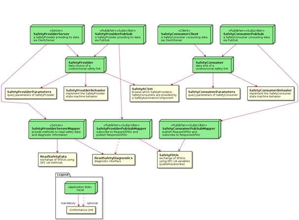
Figure 28 (informative) – Facets and ConformanceUnits
Table 42 defines the Namespace metadata for this document. The Object is used to provide version information for the Namespace and an indication about static Nodes. Static Nodes are identical for all Attributes in all Servers, including the Value Attribute. See OPC 10000-5 for more details.
The information is provided as Object of type NamespaceMetadataType. This Object is a component of the Namespaces Object that is part of the Server Object. The NamespaceMetadataType ObjectType and its Properties are defined in OPC 10000-5.
The version information is also provided as part of the ModelTableEntry in the UANodeSet XML file. The UANodeSet XML schema is defined in OPC 10000-6.
Table 42 – NamespaceMetadata Object for this document
|
Attribute |
Value |
|||
|
BrowseName |
|
|||
|
Property |
DataType |
Value |
||
|
NamespaceUri |
String |
|||
|
NamespaceVersion |
String |
1.05.04 |
||
|
NamespacePublicationDate |
DateTime |
2024-06-12 |
||
|
IsNamespaceSubset |
Boolean |
False |
||
|
StaticNodeIdTypes |
IdType [] |
0 |
||
|
StaticNumericNodeIdRange |
NumericRange [] |
|
||
|
StaticStringNodeIdPattern |
String |
|
||
Namespaces are used by OPC UA to create unique identifiers across different naming authorities. The Attributes NodeId and BrowseName are identifiers. A Node in the UA AddressSpace is unambiguously identified using a NodeId. Unlike NodeIds, the BrowseName cannot be used to unambiguously identify a Node. Different Nodes canmay have the same BrowseName. They are used to build a browse path between two Nodes or to define a standard Property.
Servers canmay often choose to use the same Nnamespace for the NodeId and the BrowseName. However, if they want to provide a standard Property, its BrowseName shall have the Nnamespace of the standards body although the Nnamespace of the NodeId reflects something else, for example the EngineeringUnits Property. All NodeIds of Nodes not defined in this document shall not use the standard namespaces.
[RQ12.1] Table 43 provides a list of mandatory and optional Namespaces used in an OPC UA Server according to this document.
Table 43 – Namespaces used in a safety Server
|
NamespaceURI |
Description |
Use |
|
http://opcfoundation.org/UA/ |
Namespace for NodeIds and BrowseNames defined in the OPC UA specification. This Namespace shall have Namespace index 0. |
Mandatory |
|
Local server URI |
Namespace for Nodes defined in the local Server. This can include types and instances used in an AutoID Device represented by the Server. This Namespace shall have Namespace index 1. |
Mandatory |
|
http://opcfoundation.org/UA/Safety |
Namespace for NodeIds and BrowseNames defined in this document. The Namespace index is Server-specific. |
Mandatory |
|
Vendor-specific types |
A Server can provide vendor-specific types like types derived from ObjectTypes defined in this document in a vendor-specific Namespace. |
Optional |
|
Vendor-specific instances |
A Server provides vendor-specific instances of the standard types or vendor-specific instances of vendor-specific types in a vendor-specific Namespace. It is recommended to separate vendor-specific types and vendor-specific instances into two or more namespaces. |
Mandatory |
Annex A
(normative)
Safety Namespace and mappings
This Annex A defines the numeric identifiers for the numeric NodeIds defined in the Namespace of this document. The identifiers are specified in a CSV file with the following syntax:
<SymbolName>, <Identifier>, <NodeClass>
Where the SymbolName is either the BrowseName of a Type Node or the BrowsePath for an Instance Node that appears in the specification and the Identifier is the numeric value for the NodeId.
The NamespaceUri for all NodeIds defined here is http://opcfoundation.org/UA/Safety
The CSV released with this version of the specification can be found here:
http://www.opcfoundation.org/UA/schemas/1.05/Opc.Ua.Safety.NodeIds.csv
The latest CSV that is compatible with this version of the specification can be found here:
http://www.opcfoundation.org/UA/schemas/Opc.Ua.Safety.NodeIds.csv
A computer processible version of the complete Information Model defined in this document is also provided. It follows the XML Information Model schema syntax defined in OPC 10000-6.
The Information Model schema released with this version of the specification can be found here:
http://www.opcfoundation.org/UA/schemas/1.05/Opc.Ua.Safety.NodeSet2.xml
The latest Information Model schema that is compatible with this version of the specification can be found here:
http://www.opcfoundation.org/UA/schemas/Opc.Ua.Safety.NodeSet2.xml
Annex B
(informative)
Additional information
B.1 CRC calculation using tables, for the polynomial 0xF4ACFB13
The calculation of a 32-bit CRC signature over an array of N octets with the help of lookup tables, using “C” as programming language, is shown below:
|
// VARIANT A: presumably easier to implement on little endian machines uint32_t crctab32[256]; // lookup table uint32_t CRC32_Backward(char *array, int16_t N){ // input is array of N octets //
containing the data,
uint32_t result = 1; // seed value for the calculated CRC int16_t i; // index for(i=N-1;i>=0;i--) // process array in reversed order result = crctab32 [((result >> 24) ^ array[i]) & 0xff] ^ (result << 8); if
(result==0) } |
where the lookup-table crctab32 has to be initialized as shown in Table B.1.
|
// VARIANT B: presumably easier to implement on big endian machines uint32_t crctab32[256]; // lookup table uint32_t CRC32_Forward(char *array, int16_t N){ // input is array of N octets // containing the data in reversed // order, see e. g. Figure 24 uint32_t result = 1; // seed value for the calculated CRC int16_t i; // index for(i=0;i<N;i++) // process array result = crctab32 [((result >> 24) ^ array[i]) & 0xff] ^ (result << 8); if (result==0) } |
where the lookup-table crctab32 has to be initialized as shown in Table B.1.
Table B.1 – The CRC32 lookup table for 32-bit CRC signature calculations
|
CRC32 lookup table (0 to 255) |
|||||||
|
00000000 |
F4ACFB13 |
1DF50D35 |
E959F626 |
3BEA1A6A |
CF46E179 |
261F175F |
D2B3EC4C |
|
77D434D4 |
8378CFC7 |
6A2139E1 |
9E8DC2F2 |
4C3E2EBE |
B892D5AD |
51CB238B |
A567D898 |
|
EFA869A8 |
1B0492BB |
F25D649D |
06F19F8E |
D44273C2 |
20EE88D1 |
C9B77EF7 |
3D1B85E4 |
|
987C5D7C |
6CD0A66F |
85895049 |
7125AB5A |
A3964716 |
573ABC05 |
BE634A23 |
4ACFB130 |
|
2BFC2843 |
DF50D350 |
36092576 |
C2A5DE65 |
10163229 |
E4BAC93A |
0DE33F1C |
F94FC40F |
|
5C281C97 |
A884E784 |
41DD11A2 |
B571EAB1 |
67C206FD |
936EFDEE |
7A370BC8 |
8E9BF0DB |
|
C45441EB |
30F8BAF8 |
D9A14CDE |
2D0DB7CD |
FFBE5B81 |
0B12A092 |
E24B56B4 |
16E7ADA7 |
|
B380753F |
472C8E2C |
AE75780A |
5AD98319 |
886A6F55 |
7CC69446 |
959F6260 |
61339973 |
|
57F85086 |
A354AB95 |
4A0D5DB3 |
BEA1A6A0 |
6C124AEC |
98BEB1FF |
71E747D9 |
854BBCCA |
|
202C6452 |
D4809F41 |
3DD96967 |
C9759274 |
1BC67E38 |
EF6A852B |
0633730D |
F29F881E |
|
B850392E |
4CFCC23D |
A5A5341B |
5109CF08 |
83BA2344 |
7716D857 |
9E4F2E71 |
6AE3D562 |
|
CF840DFA |
3B28F6E9 |
D27100CF |
26DDFBDC |
F46E1790 |
00C2EC83 |
E99B1AA5 |
1D37E1B6 |
|
7C0478C5 |
88A883D6 |
61F175F0 |
955D8EE3 |
47EE62AF |
B34299BC |
5A1B6F9A |
AEB79489 |
|
0BD04C11 |
FF7CB702 |
16254124 |
E289BA37 |
303A567B |
C496AD68 |
2DCF5B4E |
D963A05D |
|
93AC116D |
6700EA7E |
8E591C58 |
7AF5E74B |
A8460B07 |
5CEAF014 |
B5B30632 |
411FFD21 |
|
E47825B9 |
10D4DEAA |
F98D288C |
0D21D39F |
DF923FD3 |
2B3EC4C0 |
C26732E6 |
36CBC9F5 |
|
AFF0A10C |
5B5C5A1F |
B205AC39 |
46A9572A |
941ABB66 |
60B64075 |
89EFB653 |
7D434D40 |
|
D82495D8 |
2C886ECB |
C5D198ED |
317D63FE |
E3CE8FB2 |
176274A1 |
FE3B8287 |
0A977994 |
|
4058C8A4 |
B4F433B7 |
5DADC591 |
A9013E82 |
7BB2D2CE |
8F1E29DD |
6647DFFB |
92EB24E8 |
|
378CFC70 |
C3200763 |
2A79F145 |
DED50A56 |
0C66E61A |
F8CA1D09 |
1193EB2F |
E53F103C |
|
840C894F |
70A0725C |
99F9847A |
6D557F69 |
BFE69325 |
4B4A6836 |
A2139E10 |
56BF6503 |
|
F3D8BD9B |
07744688 |
EE2DB0AE |
1A814BBD |
C832A7F1 |
3C9E5CE2 |
D5C7AAC4 |
216B51D7 |
|
6BA4E0E7 |
9F081BF4 |
7651EDD2 |
82FD16C1 |
504EFA8D |
A4E2019E |
4DBBF7B8 |
B9170CAB |
|
1C70D433 |
E8DC2F20 |
0185D906 |
F5292215 |
279ACE59 |
D336354A |
3A6FC36C |
CEC3387F |
|
F808F18A |
0CA40A99 |
E5FDFCBF |
115107AC |
C3E2EBE0 |
374E10F3 |
DE17E6D5 |
2ABB1DC6 |
|
8FDCC55E |
7B703E4D |
9229C86B |
66853378 |
B436DF34 |
409A2427 |
A9C3D201 |
5D6F2912 |
|
17A09822 |
E30C6331 |
0A559517 |
FEF96E04 |
2C4A8248 |
D8E6795B |
31BF8F7D |
C513746E |
|
6074ACF6 |
94D857E5 |
7D81A1C3 |
892D5AD0 |
5B9EB69C |
AF324D8F |
466BBBA9 |
B2C740BA |
|
D3F4D9C9 |
275822DA |
CE01D4FC |
3AAD2FEF |
E81EC3A3 |
1CB238B0 |
F5EBCE96 |
01473585 |
|
A420ED1D |
508C160E |
B9D5E028 |
4D791B3B |
9FCAF777 |
6B660C64 |
823FFA42 |
76930151 |
|
3C5CB061 |
C8F04B72 |
21A9BD54 |
D5054647 |
07B6AA0B |
F31A5118 |
1A43A73E |
EEEF5C2D |
|
4B8884B5 |
BF247FA6 |
567D8980 |
A2D17293 |
70629EDF |
84CE65CC |
6D9793EA |
993B68F9 |
|
This table contains 32-bit values in hexadecimal representation for each value (0 to 255) of the argument a in the function crctab32 [a]. The table should be used line-by-line in ascending order from top left (0) to bottom right (255). For instance, crctab32[10] is highlighted using a darker background and red colour. |
|||||||
B.2.1 Unidirectional communication
The most basic type of communication is unidirectional communication, where a safety application on one device (Controller A in Figure B.1) sends data to a safety application on another device (Controller B in Figure B.1).
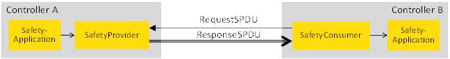
Figure B.1 – Unidirectional communication
This is accomplished by placing a SafetyProvider on Controller A and a SafetyConsumer on Controller B. The connection between SafetyProvider and SafetyConsumer can be established and terminated during runtime, allowing different consumers to connect to the same SafetyProvider at different times. Furthermore, the protocol is designed in such a way, that it is necessary for the SafetyConsumer to know the parametrized set of IDs of the SafetyProvider such that it is able to safely check whether the received data is coming from the expected source. On the other hand, as SafetyData flows in one direction only, it is not necessary for the SafetyProvider to check the ID of the SafetyConsumers. Hence, Controller A can – one after another – serve an arbitrarily large number of SafetyConsumers, and new SafetyConsumers can be introduced into the system without having to update Controller A.
B.2.2 Bidirectional communication
Bidirectional communication means the exchange of data in both directions, which is accomplished by placing a SafetyProvider and a SafetyConsumer on each controller. Hence, bidirectional communication is realized using two safety connections according to this document. See Figure B.2 for an example.
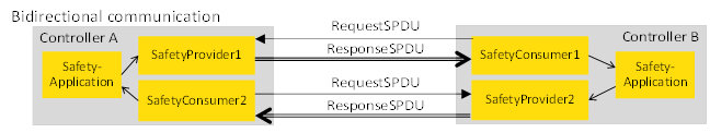
Figure B.2 – Bidirectional communication
NOTE Connections can be established and terminated during runtime.
Multicast is defined as sending the same set of data from one device (Controller A) to several other devices (Controller B1, B2,…,BN) simultaneously.
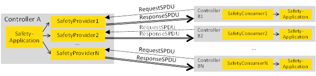
Figure B.3 – Safety multicast
Safety multicast is accomplished by placing multiple SafetyProviders on Controller A, and one SafetyConsumer on each of the Controllers B1, B2, … BN. Each of the SafetyProviders running on Controller A is connecting to one of the SafetyConsumers running on one of the Controllers B1, B2, … BN. See Figure B.3 for an example.
The safety protocol in this document is designed in such a way that:
· the state machine of the SafetyProvider has a low number of states, and thus very low memory demands,
· all safety-related message-checks are executed on the consumer and thus the computational demand on the SafetyProvider is low.
Therefore, even if many SafetyProviders are instantiated on a device, the performance requirements will still be moderate.
The properties of simple unicast are also valid for safety multicast; different sets of consumers can connect to SafetyProviders at different times, and new SafetyConsumers can be introduced into the system without having to reconfigure the SafetyProvider instances. As all SafetyProvider instances send the same safety application data (the same data source), it is irrelevant from a safety point of view to which SafetyProvider instance a given SafetyConsumer is connected. Thus, all SafetyProvider instances can be parametrized with the same set of IDs for the SafetyProvider.
B.3 Use cases for Operator Acknowledgment
This document supports operator acknowledgment both on the SafetyProvider side and on the SafetyConsumer side. For this purpose, both the interface of the SafetyProvider and the SafetyConsumer comprise a Boolean input called OperatorAckProvider and OperatorAckConsumer, respectively. The safety application can get the values of these parameters on the consumer side via the Boolean outputs OperatorAckRequested and OperatorAckProvider on the SafetyConsumer’s SAPI (see 6.3.4.2).
Subclauses B.3.2 to B.3.5 show some examples on how to use these inputs and outputs. Dashed lines indicate that the corresponding input or output is not used in the use case. For details, see 6.3.3 and 6.3.4.
B.3.2 Use case 1: unidirectional communication and OA on the SafetyConsumer side
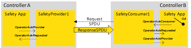
Figure B.4 – OA in unidirectional safety communication
In the scenario shown in Figure B.4, operator acknowledgment is done on the SafetyConsumer side, operator acknowledgment on the SafetyProvider side is not possible.
B.3.3 Use case 2: bidirectional communication and dual OA
Figure B.5 – Two-sided OA in bidirectional safety communication
In the scenario shown in Figure B.5, operator acknowledgment is done independently for both directions.
B.3.4 Use case 3: bidirectional communication and single, one-sided OA
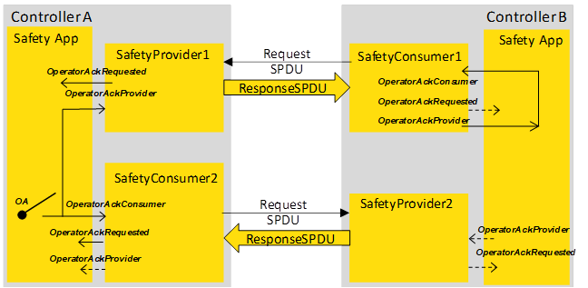
Figure B.6 – One sided OA in bidirectional safety communication
In the scenario of Figure B.6, an operator acknowledgment activated at controller A suffices for re-establishing the bidirectional connection. Both sides will cease delivering fail-safe values and continue sending process values. This is accomplished by connecting OperatorAckProvider with OperatorAckConsumer at the SafetyConsumer of controller B. Activating operator acknowledgment at controller B is not possible in this scenario.
B.3.5 Use case 4: bidirectional communication and single, two-sided OA
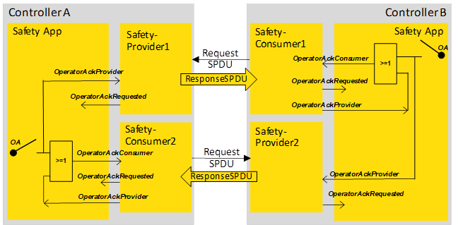
Figure B.7 – One sided OA on each side is possible
Figure B.7 shows a scenario where an operator acknowledgment activated at controller A or controller B suffices for re-establishing the bidirectional connection. Both sides will cease delivering fail-safe values and continue sending process values. This is accomplished by the logic circuits shown in the safety applications.
Annex C
(informative)
Information for assessment
This document does not make a statement on how to validate conformance. However, testing and validation of compliance can be subject to regulatory requirements.
Corresponding information regarding the testing and compliance with this document can be retrieved from the local National Committees of the IEC or from the relevant technology-specific organization for this document.
NOTE For this document, the relevant technology-specific organization is the OPC Foundation, see www.opcfoundation.com.
[1] Object Management Group, Unified Modeling Language (UML), V2.5.1, 2017, https://www.omg.org/spec/UML/2.5.1/
[3] Anwendungshinweise und Interpretationen (AIS) 20, Functionality classes and evaluation methodology for physical random number generators. Bundesamt für Sicherheit in der Informationstechnik (BSI), 1999
[4] Anwendungshinweise und Interpretationen (AIS) 31, functionality classes and evaluation methodology for physical random number generators, Bundesamt für Sicherheit in der Informationstechnik (BSI), 2001
[5] ISO/IEC 18031, Information technology, Security techniques. Random Bit Generation
[6] IEC 61000-6-7, Electromagnetic compatibility (EMC) – Part 6-7: Generic standards – Immunity requirements for equipment intended to perform functions in a safety related system (functional safety) in industrial locations
[7] IEC 61511 (all parts), Functional safety – Safety instrumented systems for the process industry sector
[8] IEC 62061, Safety of machinery – Functional safety of safety-related control systems
[9] ISO 13849 (all parts), Safety of machinery – Safety-related parts of control systems
[10] ISO 13849-1, Safety of machinery – Safety-related parts of control systems – Part 1: General principles for design
[11] IEC 62541-2, OPC Unified Architecture – Part 2: Security
[12] ISO 13849-2, Safety of machinery – Safety-related parts of control systems – Part 2: Validation
[13] IEC 62541-7, OPC Unified Architecture – Part 7: Profiles
[14] IEC 62541-8, OPC Unified Architecture – Part 8: Data Access
[15] OPC 10010 (all parts), OPC Test Lab Specification
___________