|
|
|
|
OPC 10000-22 |
|
|
OPC Unified Architecture Part 22: Base Network Model
Release 1.05.04 2024-10-15
|
|
|
|
|
OPC 10000-22 |
|
|
OPC Unified Architecture Part 22: Base Network Model
Release 1.05.04 2024-10-15
|
|
Industry Standard Specification |
Comments: |
|
|
|
|
|
|
|
|
Document |
OPC 10000-22 |
|
|
|
Title: |
OPC Unified
Architecture |
Date: |
2024-10-1501 |
|
|
|
|
|
|
Version: |
Release 1.05.04 |
Software: |
MS-Word |
|
|
|
Source: |
OPC 10000-22 - UA Specification Part 22 - Base Network Model 1.05.04.docx |
|
|
|
|
|
|
Author: |
OPC Foundation |
Status: |
Release |
|
|
|
|
|
CONTENTS
Page
3 Terms, definitions, and abbreviated terms
4.1 Type and Naming Conventions
4.2 Usage of OPC UA Interfaces
5.2.1 IIetfBaseNetworkInterfaceType Interface
5.2.2 IIeeeBaseEthernetPortType Interface
5.2.3 IIeeeAutoNegotiationStatusType Interface
5.2.4 IBaseEthernetCapabilitiesType Interface
5.2.7 IIeeeBaseTsnStreamType Interface
5.2.8 IIeeeBaseTsnTrafficSpecificationType Interface
5.2.9 IIeeeBaseTsnStatusStreamType Interface
5.2.10 IIeeeTsnInterfaceConfigurationType Interface
5.2.11 IIeeeTsnInterfaceConfigurationTalkerType Interface
5.2.12 IIeeeTsnInterfaceConfigurationListenerType Interface
5.2.13 IIeeeTsnMacAddressType Interface
5.2.14 IIeeeTsnVlanTagType Interface
5.2.15 IPriorityMappingEntryType Interface
5.4.4 NetworkInterfaces Folder
5.5.1 IetfBaseNetworkInterfaceType
5.5.2 PriorityMappingTableType
5.5.3 LldpInformationType definition
5.5.4 LldpRemoteStatisticsType definition
LldpLocalSystemType definition
5.5.5 LldpPortInformationType definition
5.5.6 LldpRemoteSystemType definition
5.6.1 UsesPriorityMappingTable ReferenceType
5.6.2 HasLowerLayerInterface ReferenceType
Annex A Modelling Examples (informative)
A.1 Modelling Examples for Network Interfaces
A.1.1 Virtual Network Interfaces
A.2 Modelling Examples for PriorityMappingEntries and IetfBaseNetworkInterface
A.3 Connecting LldpPortInformationType and IetfBaseNetworkInterfaceType
A.4 Topology Discovery with LldpRemoteSystems
A.5 Usage of BNM in other UA Specifications
A.5.1 Usage of BNM for PubSub over TSN
A.5.2 Usage of BNM in PROFINET Companion Spec
Figures
Figure 1 – Scope of Base Network Model.................................................................. 1
Figure 2 – Overview of Base Network Model.............................................................. 5
Figure 3 – Instance Entry Points for Network Interfaces, Streams, Mapping Tables and LLDP information...................................................................................................... 23
Figure 4 – IetfBaseNetworkInterfaceType................................................................ 26
Figure 5 – PriorityMappingTableType..................................................................... 28
Figure 6 – LldpInformationType............................................................................. 30
Figure A-1 – Modelling Example for virtual network interfaces...................................... 38
Figure A-2 – Modelling example for link aggregation.................................................. 39
Figure A-3 – Modelling Example for PriorityMappingTableType and IetfBaseNetworkInterface 40
Figure A-4 – Connection between LLDP and IetfInterfaces.......................................... 41
Figure A-5 – Topology Discovery via LLDP.............................................................. 42
Figure A-6 – Possible Integration of BNM into PubSub................................................ 43
Figure A-7 – Recommended Integration of BNM into Companion Spec exemplified by PROFINET 44
Tables
Table 1 – IIetfBaseNetworkInterfaceType definition
Table 2 – IIetfBaseNetworkInterfaceType Attribute values for child Nodes
Table 3 – IIeeeBaseEthernetPortType definition
Table 4 – IIeeeBaseEthernetPortType Attribute values for child Nodes
Table 5 – IIeeeAutoNegotiationStatusType definition
Table 6 – IBaseEthernetCapabilitiesType definition
Table 7 – IVlanIdType definition
Table 8 – ISrClassType definition
Table 9 – IIeeeBaseTsnStreamType definition
Table 10 – IIeeeBaseTsnTrafficSpecificationType definition
Table 11 – IIeeeBaseTsnStatusStreamType definition
Table 12 – IIeeeTsnInterfaceConfigurationType definition
Table 13 – IIeeeTsnInterfaceConfigurationTalkerType definition
Table 14 – IIeeeTsnInterfaceConfigurationListenerType definition
Table 15 – IIeeeTsnMacAddressType definition
Table 16 – IIeeeTsnVlanTagType definition
Table 17 – IPriorityMappingEntryType definition
Table 20 – InterfaceAdminStatus Values
Table 21 – InterfaceAdminStatus Definition
Table 22 – InterfaceOperStatus Values
Table 23 – InterfaceOperStatus Definition
Table 24 – NegotiationStatus Values
Table 25 – NegotiationStatus Definition
Table 26 – TsnFailureCode values
Table 27 – TsnFailureCode Definition
Table 28 – TsnStreamState Values
Table 29 – TsnStreamState Definition
Table 30 – TsnTalkerStatus Values
Table 31 – TsnTalkerStatus Definition
Table 32 – TsnListenerStatus Values
Table 33 – TsnListenerStatus Definition
Table 34 – ChassisIdSubtype Values
Table 35 – ChassisIdSubtype Definition
Table 36 – PortIdSubtype Values
Table 37 – PortIdSubtype Definition
Table 38 – ManAddrIfSubtype Values
Table 39 – ManAddrIfSubtype Definition
Table 40 – PriorityMappingEntryType structure
Table 41 – PriorityMappingEntryType Definition
Table 42 – LldpManagementAddressTxPortType structure
Table 43 – LldpManagementAddressTxPortType Definition
Table 44 – LldpManagementAddressType structure
Table 45 – LldpManagementAddressType Definition
Table 46 – LldpTlvType structure
Table 47 – LldpTlvType Definition
Table 48 – LldpSystemCapabilitiesMap OptionSet
Table 49 – LldpSystemCapabilitiesMap OptionSet Definition
Table 50 – Resources definition
Table 51 – Communication definition
Table 52 – MappingTables definition
Table 53 – NetworkInterfaces definition
Table 55 – TalkerStreams definition
Table 56 – ListenerStreams definition
Table 58 – IetfBaseNetworkInterfaceType definition
Table 59 – IetfBaseNetworkInterfaceType Attribute values for child Nodes
Table 60 – IetfBaseNetworkInterfaceType Additional References
Table 61 – PriorityMappingTableType definition
Table 62 – AddPriorityMappingEntry Method arguments
Table 63 – AddPriorityMappingEntry Method result codes
Table 64 – AddPriorityMappingEntry Method AddressSpace definition
Table 65 – DeletePriorityMappingEntry Method arguments
Table 66 – DeletePriorityMappingEntry Method result codes
Table 67 – DeletePriorityMappingEntry Method AddressSpace definition
Table 68 – LldpInformationType definition
Table 69 - LldpInformationType Addtional Components
Table 70 – LldpRemoteStatisticsType definition
Table 71 – LldpLocalSystemType definition
Table 72 – LldpPortInformationType definition
Table 73 - LldpPortInformationType additional subcomponents
Table 74 – LldpRemoteSystemType definition
Table 75 – UsesPriorityMappingTable definition
Table 76 – HasLowerLayerInterface definition
OPC Foundation
____________
UNIFIED ARCHITECTURE
This specification is the specification for developers of OPC UA applications. The specification is a result of an analysis and design process to develop a standard interface to facilitate the development of applications by multiple vendors that shall inter-operate seamlessly together.
Copyright © 2006-2024, OPC Foundation, Inc.
COPYRIGHT RESTRICTIONS
Any unauthorized use of this specification may violate copyright laws, trademark laws, and communications regulations and statutes. This document contains information which is protected by copyright. All Rights Reserved. No part of this work covered by copyright herein may be reproduced or used in any form or by any means--graphic, electronic, or mechanical, including photocopying, recording, taping, or information storage and retrieval systems--without permission of the copyright owner.
OPC Foundation members and non-members are prohibited
from copying and redistributing this specification. All copies must be obtained
on an individual basis, directly from the OPC Foundation Web site
http://www.opcfoundation.org.
PATENTS
The attention of adopters is directed to the possibility that compliance with or adoption of OPC specifications may require use of an invention covered by patent rights. OPC shall not be responsible for identifying patents for which a license may be required by any OPC specification, or for conducting legal inquiries into the legal validity or scope of those patents that are brought to its attention. OPC specifications are prospective and advisory only. Prospective users are responsible for protecting themselves against liability for infringement of patents.
WARRANTY AND LIABILITY DISCLAIMERS
WHILE THIS PUBLICATION IS BELIEVED TO BE ACCURATE, IT IS PROVIDED "AS IS" AND MAY CONTAIN ERRORS OR MISPRINTS. THE OPC FOUDATION MAKES NO WARRANTY OF ANY KIND, EXPRESSED OR IMPLIED, WITH REGARD TO THIS PUBLICATION, INCLUDING BUT NOT LIMITED TO ANY WARRANTY OF TITLE OR OWNERSHIP, IMPLIED WARRANTY OF MERCHANTABILITY OR WARRANTY OF FITNESS FOR A PARTICULAR PURPOSE OR USE. IN NO EVENT SHALL THE OPC FOUNDATION BE LIABLE FOR ERRORS CONTAINED HEREIN OR FOR DIRECT, INDIRECT, INCIDENTAL, SPECIAL, CONSEQUENTIAL, RELIANCE OR COVER DAMAGES, INCLUDING LOSS OF PROFITS, REVENUE, DATA OR USE, INCURRED BY ANY USER OR ANY THIRD PARTY IN CONNECTION WITH THE FURNISHING, PERFORMANCE, OR USE OF THIS MATERIAL, EVEN IF ADVISED OF THE POSSIBILITY OF SUCH DAMAGES.
The entire risk as to the quality and performance of software developed using this specification is borne by you.
RESTRICTED RIGHTS LEGEND
This Specification is provided with Restricted Rights. Use, duplication or disclosure by the U.S. government is subject to restrictions as set forth in (a) this Agreement pursuant to DFARs 227.7202-3(a); (b) subparagraph (c)(1)(i) of the Rights in Technical Data and Computer Software clause at DFARs 252.227-7013; or (c) the Commercial Computer Software Restricted Rights clause at FAR 52.227-19 subdivision (c)(1) and (2), as applicable. Contractor / manufacturer are the OPC Foundation, 16101 N. 82nd Street, Suite 3B, Scottsdale, AZ, 85260-1830.
COMPLIANCE
The OPC Foundation shall at all times be the sole entity that may authorize developers, suppliers and sellers of hardware and software to use certification marks, trademarks or other special designations to indicate compliance with these materials. Products developed using this specification may claim compliance or conformance with this specification if and only if the software satisfactorily meets the certification requirements set by the OPC Foundation. Products that do not meet these requirements may claim only that the product was based on this specification and must not claim compliance or conformance with this specification.
Trademarks
Most computer and software brand names have trademarks or registered trademarks. The individual trademarks have not been listed here.
GENERAL PROVISIONS
Should any provision of this Agreement be held to be void, invalid, unenforceable or illegal by a court, the validity and enforceability of the other provisions shall not be affected thereby.
This Agreement shall be governed by and construed under the laws of the State of Minnesota, excluding its choice or law rules.
This Agreement embodies the entire understanding between the parties with respect to, and supersedes any prior understanding or agreement (oral or written) relating to, this specification.
ISSUE REPORTING
The OPC Foundation strives to maintain the highest quality standards for its published specifications; hence they undergo constant review and refinement. Readers are encouraged to report any issues and view any existing errata here: http://www.opcfoundation.org/errata
Revision 1.05.04 Highlights
The following table includes the Mantis issues resolved with this revision.
|
Mantis ID |
Scope |
Summary |
Resolution |
|
9056 |
Feature |
Part 22 needs to model LLDP neighbour information |
Types were added model local and remote LLDP information |
|
9834 |
Clarification |
Missing external normative references |
The Normative references section was updated with references to all RFCs and IEEE specifications referenced. |
The Base Network Model (BNM) specifies an OPC UA Information Model for a basic set of network related components to be used in other Information Models.
The initial version of this document defines parameter sets for TSN Talkers and Listeners as well as network interfaces and ports as shown in Figure 1. A future version of this document is expected to have a broader scope of other network technologies than Ethernet only.
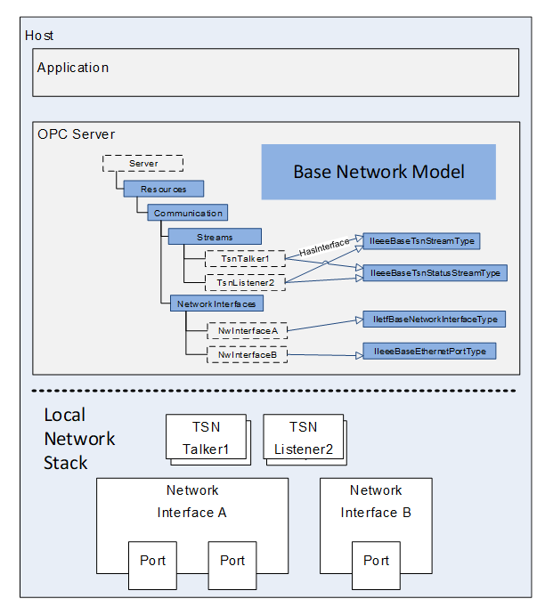
Figure 1 – Scope of Base Network Model
The following referenced documents are indispensable for the application of this OPC UA part. For dated references, only the edition cited applies. For undated references, the latest edition of the referenced document (including any amendments and errata) applies.
OPC 10000-1, OPC Unified Architecture - Part 1: Overview and Concepts
http://www.opcfoundation.org/UA/Part1/
OPC 10000-3, OPC Unified Architecture - Part 3: Address Space Model
http://www.opcfoundation.org/UA/Part3/
OPC 10000-5, OPC Unified Architecture - Part 5: Information Model
http://www.opcfoundation.org/UA/Part5/
OPC 10000-8, OPC Unified Architecture - Part 8: Data Access
http://www.opcfoundation.org/UA/Part8/
IEEE 802.3-2022, ETHERNET
IEEE 802.1Q-2018, IEEE Standard for Local and Metropolitan Area Networks Bridges and Bridged Networks
IEEE 802.1Qcc-2018, Bridges and Bridged Networks, Amendment: Stream Reservation Protocol (SRP) Enhancements and Performance Improvements
IEEE 802-2014, IEEE Standard for Local and Metropolitan Area Networks: Overview and Architecture
IEEE 802.1AB-2016, IEEE Standard for Local and metropolitan area networks - Station and Media Access Control Connectivity Discovery
IEEE 802.1ABcu-2021, IEEE Standard for Local and metropolitan networks--Station and Media Access Control Connectivity Discovery Amendment 1: YANG Data Model
IETF RFC 2021, Remote Network Monitoring Management Information Base Version 2 using SMIv2
https://tools.ietf.org/html/rfc2021
IETF RFC 2863, The Interfaces Group MIB
https://tools.ietf.org/html/rfc2863
IETF RFC 2737, Entity MIB (Version 2)
https://tools.ietf.org/html/rfc2737
IETF RFC 3046, DHCP Relay Agent Information Option
https://tools.ietf.org/html/rfc3046
IETF RFC 3232, Assigned Numbers: RFC 1700 is Replaced by an On-line Database
https://tools.ietf.org/html/rfc3232
IETF RFC 3418, Management Information Base (MIB) for the Simple Network Management Protocol (SNMP)
https://tools.ietf.org/html/rfc3418
IETF RFC 4639, Cable Device Management Information Base for Data-Over-Cable Service Interface Specification (DOCSIS) Compliant Cable Modems and Cable Modem Termination Systems
https://tools.ietf.org/html/rfc4639
IETF RFC 8343, A YANG Data Model for Interface Management
https://tools.ietf.org/html/rfc8343
For the purposes of this document, the terms and definitions given in OPC 10000-1, OPC 10000-3, OPC 10000-5 and OPC 10000-8 apply.
All used terms are italicized in this document.
AVB Audio Video Bridging
BNM Base Network Model
CNC Centralized Network Configuration
CUC Centralized User Configuration
DSCP Differentiated services code point for packet classification purposes
IEEE Institute of Electrical and Electronics Engineers
IETF Internet Engineering Task Force
MAU Medium Attachment Units
MIB Management Information Base
PCP Priority Code Point for classifying and managing network traffic
TSN Time Sensitive Networks
VLAN Virtual Local Area Network
YANG Yet Another Next Generation (Data modelling language for network management)
The BNM shall align its parameters to existing standards defined by IETF and the IEEE to allow an effortless mapping against existing network technologies. Therefore, selected DataTypes shall fit to the types used by the related managed objects of IEEE and IETF. BrowseNames of Variables and parameter sets (UA interface) are preferably derived from standardized IETF / IEEE YANG models. If no standardized YANG representation is available, MIB definitions are chosen.
The parameters of the BNM are grouped in the form of OPC UA Interfaces. Interfaces have been chosen to define parameter sets independent of the implementation in future ObjectType hierarchies. This allows these grouped parameters to be used in other Information Models independent of ObjectType hierarchies that can be found in the BNM.
It is expected that a future version of the BNM will define a collection of network related ObjectTypes.
The Base Network Model defined in this document is shown in Figure 2.
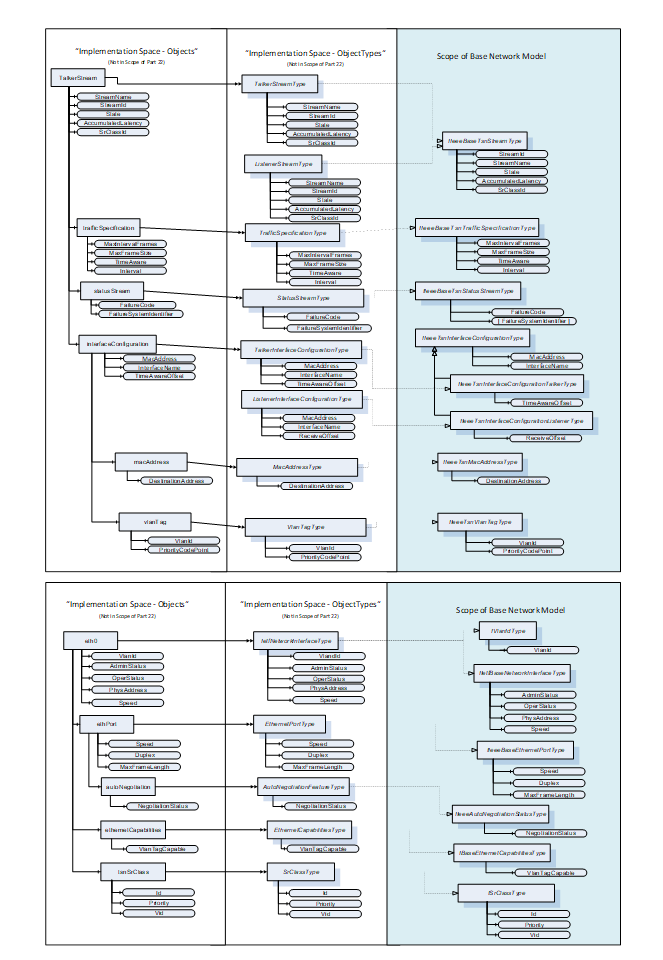
Figure 2 – Overview of Base Network Model
This OPC UA Interface defines the basis of an IETF network interface. The IIetfBaseNetworkInterfaceType is formally defined in Table 1.
Table 1 – IIetfBaseNetworkInterfaceType definition
|
Attribute |
Value |
||||
|
BrowseName |
IIetfBaseNetworkInterfaceType |
||||
|
IsAbstract |
True |
||||
|
References |
NodeClass |
BrowseName |
DataType |
TypeDefinition |
ModellingRule |
|
Subtype of the BaseInterfaceType defined in OPC 10000-5 |
|||||
|
HasComponent |
Variable |
AdminStatus |
InterfaceAdminStatus |
BaseDataVariableType |
Mandatory |
|
HasComponent |
Variable |
OperStatus |
InterfaceOperStatus |
BaseDataVariableType |
Mandatory |
|
HasComponent |
Variable |
PhysAddress |
String |
BaseDataVariableType |
Optional |
|
HasComponent |
Variable |
Speed |
UInt64 |
AnalogUnitType |
Mandatory |
|
Conformance Units |
|||||
|
BNM Ethernet Base Info |
|||||
AdminStatus of DataType InterfaceAdminStatus specifies the desired state of the network interface. This Variable has the same read semantics as ifAdminStatus (ifAdminStatus is defined in IETF RFC 2863). The InterfaceAdminStatus Enumeration is defined in 5.3.1.2.
OperStatus of DataType InterfaceOperStatus specifies the current operational state of the network interface. This Variable has the same semantics as ifOperStatus (ifOperStatus is defined in IETF RFC 2863). The InterfaceOperStatus Enumeration is defined in 5.3.1.3.
PhysAddress of DataType String specifies the network interface's address at its protocol sub-layer. For example, for an 802.x network interface, this parameter normally contains a Media Access Control (MAC) address. The network interface's media-specific modules must define the bit and byte ordering and the format of the value of this object. For network interfaces that do not have such an address (e.g., a serial line), this node is not present (ifPhysAddress is defined in IETF RFC 2863).
Speed of DataType UInt64 specifies an estimate of the network interface's current bandwidth in bits per second. For network interfaces that do not vary in bandwidth or for those where no accurate estimation can be made, this value should contain the nominal bandwidth (ifSpeed and ifHighSpeed are defined in IETF RFC 2863).
The component Variables of the IIetfBaseNetworkInterfaceType have the Attribute values defined in Table 2.
Table 2 – IIetfBaseNetworkInterfaceType Attribute values for child Nodes
|
Source Path |
Value Attribute |
Description Attribute |
||
|
NamespaceUri: http://www.opcfoundation.org/UA/units/un/cefact UnitId: 4337968 |
- |
This OPC UA Interface defines capabilities of an Ethernet-based port. The IIeeeBaseEthernetPortType is formally defined in Table 3.
Table 3 – IIeeeBaseEthernetPortType definition
|
Attribute |
Value |
||||
|
BrowseName |
IIeeeBaseEthernetPortType |
||||
|
IsAbstract |
True |
||||
|
References |
NodeClass |
BrowseName |
DataType |
TypeDefinition |
Modelling Rule |
|
Subtype of the BaseInterfaceType defined in OPC 10000-5 |
|||||
|
HasComponent |
Variable |
Speed |
UInt64 |
AnalogUnitType |
Mandatory |
|
HasComponent |
Variable |
Duplex |
Duplex |
BaseDataVariableType |
Mandatory |
|
HasComponent |
Variable |
MaxFrameLength |
UInt16 |
BaseDataVariableType |
Mandatory |
|
Conformance Units |
|||||
|
BNM Ethernet Base Info |
|||||
Speed of DataType UInt64 specifies the configured, negotiated, or actual speed of an Ethernet port in entities of 1 Mb/s (data rate). The default value is implementation-dependent (Ethernet ports are defined in IEEE 802.3-2022).
Duplex of DataType Duplex represents the configured, negotiated, or actual duplex mode of an Ethernet port (aDuplexStatus is defined in IEEE 802.3-2022, clause 30.3.1.1.32, aDuplexStatus). The Duplex DataType is defined in 5.3.1.1.
MaxFrameLength of DataType UInt16 indicates the MAC frame length (including FCS bytes) at which frames are dropped for being too long (aMaxFrameLength is defined in IEEE 802.3-2022, clause 30.3.1.1.37, aMaxFrameLength).
The component Variables of the IIeeeBaseEthernetPortType have the Attribute values defined in Table 4.
Table 4 – IIeeeBaseEthernetPortType Attribute values for child Nodes
|
Source Path |
Value Attribute |
Description Attribute |
||
|
NamespaceUri: http://www.opcfoundation.org/UA/units/un/cefact UnitId: 4534832 |
- |
This OPC UA Interface defines the auto negotiation status of an Ethernet-based port. The IIeeeAutoNegotiationStatusType is formally defined in Table 5.
Table 5 – IIeeeAutoNegotiationStatusType definition
|
Attribute |
Value |
||||
|
BrowseName |
IIeeeAutoNegotiationStatusType |
||||
|
IsAbstract |
True |
||||
|
References |
NodeClass |
BrowseName |
DataType |
TypeDefinition |
Modelling Rule |
|
Subtype of the BaseInterfaceType defined in OPC 10000-5 |
|||||
|
HasComponent |
Variable |
NegotiationStatus |
NegotiationStatus |
BaseDataVariableType |
Mandatory |
|
Conformance Units |
|||||
|
BNM AutoNeg |
|||||
NegotiationStatus of DataType NegotiationStatus specifies the status of the auto-negotiation protocol (aAutoNegAutoConfig is defined in IEEE 802.3-2022, clause 30.6.1.1.4, aAutoNegAutoConfig). The NegotiationStatus DataType is defined in 5.3.1.4.
This OPC UA Interface defines if an Ethernet-based port is VLAN Tag capable. The IBaseEthernetCapabilitiesType is formally defined in Table 6.
Table 6 – IBaseEthernetCapabilitiesType definition
|
Attribute |
Value |
||||
|
BrowseName |
IBaseEthernetCapabilitiesType |
||||
|
IsAbstract |
True |
||||
|
References |
NodeClass |
BrowseName |
DataType |
TypeDefinition |
Modelling Rule |
|
Subtype of the BaseInterfaceType defined in OPC 10000-5 |
|||||
|
HasComponent |
Variable |
VlanTagCapable |
Boolean |
BaseDataVariableType |
Mandatory |
|
Conformance Units |
|||||
|
BNM VLAN Capabilities |
|||||
When VlanTagCapable is true, the network interface supports the ability to tag/untag frames using a Customer VLAN Tag (C-TAG of clause 9) provided by the network (VLAN Tags are defined in IEEE 802.1Qcc-2018, clause 46.2.3.7.1).
This OPC UA Interface specifies a VLAN Id to be associated with a network interface. The IVlanIdType is formally defined in Table 7.
Table 7 – IVlanIdType definition
|
Attribute |
Value |
||||
|
BrowseName |
IVlanIdType |
||||
|
IsAbstract |
True |
||||
|
References |
NodeClass |
BrowseName |
DataType |
TypeDefinition |
Modelling Rule |
|
Subtype of the BaseInterfaceType defined in OPC 10000-5 |
|||||
|
HasComponent |
Variable |
VlanId |
UInt16 |
BaseDataVariableType |
Mandatory |
|
Conformance Units |
|||||
|
BNM IETF Interface Vlan Info |
|||||
VlanId is an UInt16 and contains the Customer VLAN Tag (IEEE 802.1Q-2018 C-TAG of clause 9) that frames injected at this network interface will be tagged with (VlanId is defined in IEEE 802.1Qcc-2018 clause 46.2.3.7.1).
This OPC UA Interface defines the content of an SrClass. The ISrClassType is formally defined in Table 8.
Table 8 – ISrClassType definition
|
Attribute |
Value |
||||
|
BrowseName |
ISrClassType |
||||
|
IsAbstract |
True |
||||
|
References |
NodeClass |
BrowseName |
DataType |
TypeDefinition |
Modelling Rule |
|
Subtype of the BaseInterfaceType defined in OPC 10000-5 |
|||||
|
HasComponent |
Variable |
Id |
Byte |
BaseDataVariableType |
Mandatory |
|
HasComponent |
Variable |
Priority |
Byte |
BaseDataVariableType |
Mandatory |
|
HasComponent |
Variable |
Vid |
UInt16 |
BaseDataVariableType |
Mandatory |
|
Conformance Units |
|||||
|
BNM TSN Base Info |
|||||
Id is a Byte and specifies the SRclassID in a numeric representation of the SR classes which is supported by a particular Bridge Port (SRclassID is defined in IEEE 802.1Q-2018, clause 35.2.2.9.2, SRclassID). Only Values between 0 and 7 shall be used.
Priority is a Byte and holds the Data Frame Priority (item a in IEEE 802.1Q-2018 clause 35.2.2.8.5) value that will be used for streams that belong to the associated SR class. (SRclassPriority is defined in IEEE 802.1Q-2018, clause 35.2.2.9.3, SRclassPriority). Only Values between 0 and 7 shall be used.
Vid is an UInt16 and contains the SR_PVID (item i) in IEEE 802.1Q-2018 clause 35.2.1.4) that the associated streams will be tagged with by the Talker (SRclassVID is defined in IEEE 802.1Q-2018, clause 35.2.2.9.4, SRclassVID).
The IIeeeBaseTsnStreamType contains Variables which are common for both TSN talkers and TSN listeners. They represent the configuration properties and diagnostic values like reservation status and failure codes of a TSN stream. The IIeeeBaseTsnStreamType is formally defined Table 9.
Table 9 – IIeeeBaseTsnStreamType definition
|
Attribute |
Value |
||||
|
BrowseName |
IIeeeBaseTsnStreamType |
||||
|
IsAbstract |
True |
||||
|
References |
NodeClass |
BrowseName |
DataType |
TypeDefinition |
ModellingRule |
|
Subtype of the BaseInterfaceType defined in OPC 10000-5 |
|||||
|
HasComponent |
Variable |
StreamId |
Byte[8] |
BaseDataVariableType |
Mandatory |
|
HasComponent |
Variable |
StreamName |
String |
BaseDataVariableType |
Mandatory |
|
HasComponent |
Variable |
State |
TsnStreamState |
BaseDataVariableType |
Mandatory |
|
HasComponent |
Variable |
AccumulatedLatency |
UInt32 |
BaseDataVariableType |
Optional |
|
HasComponent |
Variable |
SrClassId |
Byte |
BaseDataVariableType |
Optional |
|
Conformance Units |
|||||
|
BNM TSN Base Info |
|||||
StreamId is an array of 8 Bytes defined according to the StreamID in IEEE 802.1Qcc-2018 clause 35.2.2.8.2. The StreamId shall be unique in the scope of the related TSN Network. The mapping between the StreamId Byte array and the IEEE octet string StreamID is as follows: Entry[n] of StreamId is mapped to octet[n] of StreamID. The StreamId shall be provided in the TSN stream Objects for diagnostic reasons.
Note: In the distributed configuration model the StreamId is typically generated by the TSN control stack of the endstation. In the fully centralized configuration model the StreamId is typically generated by the CUC.
StreamName is a String identifying the related stream in the network. The format of the String is application specific. The uniqueness of the StreamName inside the network segment shall be guaranteed by the application. If multiple applications use the network segment, they need to agree on a naming scheme.
State represents the current state of the TSN configuration process of a TSN stream. The TsnStreamState Enumeration is defined in 5.3.1.6.
AccumulatedLatency of DataType UInt32 is the maximum worst case propagation delay in nanoseconds calculated and guaranteed by the TSN Control Layer for this Listener. Once the stream reservation has succeeded the AccumulatedLatency is not expected to increase during the lifecycle of the TSN Stream (AccumulatedLatency is defined in IEEE 802.1Q-2018 clause 35.2.2.8.6).
SrClassId of DataType Byte contains the Stream Reservation Class that is used for this stream (as defined in IEEE 802.1Qcc-2018 clause 35.2.2.9.2).
This OPC UA Interface is used to represent the traffic specification of a TSN stream. The IIeeeBaseTsnTrafficSpecificationType is formally defined in Table 10.
Table 10 – IIeeeBaseTsnTrafficSpecificationType definition
|
Attribute |
Value |
||||
|
BrowseName |
IIeeeBaseTsnTrafficSpecificationType |
||||
|
IsAbstract |
True |
||||
|
References |
NodeClass |
BrowseName |
DataType |
TypeDefinition |
Modelling Rule |
|
Subtype of the BaseInterfaceType defined in OPC 10000-5 |
|||||
|
HasComponent |
Variable |
MaxIntervalFrames |
UInt16 |
BaseDataVariableType |
Mandatory |
|
HasComponent |
Variable |
MaxFrameSize |
UInt32 |
BaseDataVariableType |
Mandatory |
|
HasComponent |
Variable |
Interval |
UnsignedRationalNumber |
BaseDataVariableType |
Mandatory |
|
Conformance Units |
|||||
|
BNM TSN Config |
|||||
The MaxFrameSize of DataType UInt16 specifies the maximum size frame that will be sent by a Talker for this Stream (as defined in IEEE 802.1Q-2018 clause 35.2.2.8.4a).
Note: According to 802.1Q MaxFrameSize only counts the number of bytes of the Ethernet payload without the media specific framing bytes. (i.e. without 8-byte preamble, 14-byte IEEE 802.3 header, 4-byte IEEE 802.1Q priority/VID Tag, 4-byte CRC, 12-byte inter frame gap). Same rules apply for counting MaxBytesPerInterval.
The MaxIntervalFrames of DataType UInt16 Variable specifies the maximum number of frames that will be sent during an Interval. (as defined in IEEE 802.1Q-2018, clause 35.2.2.8.4b, “MaxIntervalFrames” or IEEE 802.1Qcc-2018, clause 35.2.2.10.6, “MaxFramesPerInterval”)
Interval of DataType UnsignedRationalNumber defines the time period of the TSN Stream in nanoseconds. In that interval a specified number of frames (MaxIntervalFrames) with a maximum payload size per frame (MaxFrameSize) and a maximum total number of bytes (MaxBytesPerInterval) will be transmitted. The Interval therefore shall either represent the “class measurement interval” as used for AVB based Streams (as defined in IEEE 802.1Q-2018 clause 35 or the “Interval” parameter used in the TrafficSpecification group in IEEE 802.1Qcc-2018 clause 46.2.3.5.1).
This OPC UA Interface is used to represent the status of a TSN stream. The IIeeeBaseTsnStatusStreamType is formally defined in Table 11.
Table 11 – IIeeeBaseTsnStatusStreamType definition
|
Attribute |
Value |
||||
|
BrowseName |
IIeeeBaseTsnStatusStreamType |
||||
|
IsAbstract |
True |
||||
|
References |
NodeClass |
BrowseName |
DataType |
TypeDefinition |
ModellingRule |
|
Subtype of the BaseInterfaceType defined in OPC 10000-5 |
|||||
|
HasComponent |
Variable |
TalkerStatus |
TsnTalkerStatus |
BaseDataVariableType |
Optional |
|
HasComponent |
Variable |
ListenerStatus |
TsnListenerStatus |
BaseDataVariableType |
Optional |
|
HasComponent |
Variable |
FailureCode |
TsnFailureCode |
BaseDataVariableType |
Mandatory |
|
HasComponent |
Variable |
FailureSystemIdentifier |
Byte[][8] |
BaseDataVariableType |
Mandatory |
|
Conformance Units |
|||||
|
BNM TSN Base Info |
|||||
TalkerStatus of DataType TsnTalkerStatus contains the Reservation Failure Code as defined in the “FailureInformation” in IEEE 802.1Qcc-2018 clause 46.2.5.1.1.
ListenerStatus of DataType TsnListenerStatus contains the Reservation Failure Code as defined in the “FailureInformation” in IEEE 802.1Qcc-2018 clause 46.2.5.1.2.
FailureCode of DataType TsnFailureCode contains the Reservation Failure Code as defined in the “FailureInformation” in IEEE 802.1Qcc-2018 clause 46.2.5.1.3.
FailureSystemIdentifier is an Array of Arrays of 8 Bytes and contains the System Identifiers representing the network nodes where the failure occurred (as defined in “System Identifier” in “FailureInformation” in IEEE 802.1Q-2018 clause 35.2.2.8.7).
This OPC UA Interface is used to represent an interface configuration which is part of a TSN stream (on the end-device). The IIeeeTsnInterfaceConfigurationType is formally defined in Table 12.
Table 12 – IIeeeTsnInterfaceConfigurationType definition
|
Attribute |
Value |
||||
|
BrowseName |
IIeeeTsnInterfaceConfigurationType |
||||
|
IsAbstract |
True |
||||
|
References |
NodeClass |
BrowseName |
DataType |
TypeDefinition |
ModellingRule |
|
Subtype of the BaseInterfaceType defined in OPC 10000-5 |
|||||
|
HasComponent |
Variable |
MacAddress |
String |
BaseDataVariableType |
Mandatory |
|
HasComponent |
Variable |
InterfaceName |
String |
BaseDataVariableType |
Optional |
|
Conformance Units |
|||||
|
BNM TSN Config |
|||||
MacAddress of DataType String contains the MAC Address of the Interface the configuration will be applied to, as defined in IEEE 802.1Qcc-2018, clause 46.2.5.3.
InterfaceName of DataType String is optional and supports the identification of the Interface to be configured, as defined in IEEE 802.1Qcc-2018, clause 46.2.5.3.
This OPC UA Interface is used to represent a talker (sender) interface configuration of a TSN stream. The IIeeeTsnInterfaceConfigurationTalkerType is formally defined in Table 13.
Table 13 – IIeeeTsnInterfaceConfigurationTalkerType definition
|
Attribute |
Value |
||||
|
BrowseName |
IIeeeTsnInterfaceConfigurationTalkerType |
||||
|
IsAbstract |
True |
||||
|
References |
NodeClass |
BrowseName |
DataType |
TypeDefinition |
ModellingRule |
|
Subtype of the IIeeeTsnInterfaceConfigurationType defined in 5.2.10 |
|||||
|
HasComponent |
Variable |
TimeAwareOffset |
UInt32 |
BaseDataVariableType |
Optional |
|
Conformance Units |
|||||
|
BNM TSN Config |
|||||
TimeAwareOffset of DataType UInt32 specifies the time offset in nanoseconds relative to the start of the Interval that the Talker shall use for transmission (as defined in IEEE 802.1Qcc-2018 clause 46.2.5.3.5).
This OPC UA Interface is used to represent a listener (receiver) interface configuration of a TSN stream. The IIeeeTsnInterfaceConfigurationListenerType is formally defined in Table 14.
Table 14 – IIeeeTsnInterfaceConfigurationListenerType definition
|
Attribute |
Value |
||||
|
BrowseName |
IIeeeTsnInterfaceConfigurationListenerType |
||||
|
IsAbstract |
True |
||||
|
References |
NodeClass |
BrowseName |
DataType |
TypeDefinition |
ModellingRule |
|
Subtype of the IIeeeTsnInterfaceConfigurationType defined in 5.2.10 |
|||||
|
HasComponent |
Variable |
ReceiveOffset |
UInt32 |
BaseDataVariableType |
Optional |
|
Conformance Units |
|||||
|
BNM TSN Config |
|||||
ReceiveOffset of DataType UInt32 specifies the offset in nanoseconds within the Interval at which the Listener will receive the first frame of the TSN Stream.
This OPC UA Interface is used to represent a MAC address based stream identification of a TSN stream. The IIeeeTsnMacAddressType is formally defined in Table 15.
Table 15 – IIeeeTsnMacAddressType definition
|
Attribute |
Value |
||||
|
BrowseName |
IIeeeTsnMacAddressType |
||||
|
IsAbstract |
True |
||||
|
References |
NodeClass |
BrowseName |
DataType |
TypeDefinition |
ModellingRule |
|
Subtype of the BaseInterfaceType defined in OPC 10000-5 |
|||||
|
HasComponent |
Variable |
DestinationAddress |
Byte[6] |
BaseDataVariableType |
Mandatory |
|
HasComponent |
Variable |
SourceAddress |
Byte[6] |
BaseDataVariableType |
Optional |
|
Conformance Units |
|||||
|
BNM TSN Config |
|||||
DestinationAddress is defined according to the destination_mac_address in IEEE 802.1Qcc-2018 clause 46.2.3.4.1, which represents the destination MAC address in the Ethernet header of the streamed data packets. Entry[n] of DestinationAddress is mapped to octet[n] of destination_mac_address.
SourceAddress is defined according to the source_mac_address in IEEE 802.1Qcc-2018 clause 46.2.3.4.1, which represents the source MAC address in the Ethernet header of the streamed data packets. Entry[n] of SourceAddress is mapped to octet[n] of source_mac_address.
This OPC UA Interface is used to represent the VLAN configuration of a TSN stream. The IIeeeTsnVlanTagType is formally defined in Table 16.
Table 16 – IIeeeTsnVlanTagType definition
|
Attribute |
Value |
||||
|
BrowseName |
IIeeeTsnVlanTagType |
||||
|
IsAbstract |
True |
||||
|
References |
NodeClass |
BrowseName |
DataType |
TypeDefinition |
ModellingRule |
|
Subtype of the BaseInterfaceType defined in OPC 10000-5 |
|||||
|
HasComponent |
Variable |
VlanId |
UInt16 |
BaseDataVariableType |
Mandatory |
|
HasComponent |
Variable |
PriorityCodePoint |
Byte |
BaseDataVariableType |
Mandatory |
|
Conformance Units |
|||||
|
BNM TSN Config |
|||||
VlanId of DataType UInt16 defines the 12-Bit VLAN-Identifier of the VLAN tag in the Ethernet header for the related stream. Only values between 0 and 4095 shall be used according to IEEE 802.1Q-2018 Table 9-2.
PriorityCodePoint of DataType Byte defines the 3 Bit priority code point inside the VLAN tag of the Ethernet header of the related stream. Only values between 0 and 7 are supported as defined by IEEE 802.1Q-2018, clause 35.2.2.8.5a, Data Frame Priority.
This OPC UA Interface is used to translate a priority label like PriorityLabel (defined in Part 14) to a concrete network priority value (e.g. DSCP or PCP).
Note: This UA Interface is typically used to form a mapping rule table containing a set of object entities implementing the IPriorityMappingEntryType. Each network interface supporting priority mapping can reference such a mapping table Object.
Table 17 – IPriorityMappingEntryType definition
|
Attribute |
Value |
||||
|
BrowseName |
IPriorityMappingEntryType |
||||
|
IsAbstract |
True |
||||
|
References |
NodeClass |
BrowseName |
DataType |
TypeDefinition |
ModellingRule |
|
Subtype of the BaseInterfaceType defined in OPC 10000-5 |
|||||
|
HasComponent |
Variable |
MappingUri |
String |
BaseDataVariableType |
Mandatory |
|
HasComponent |
Variable |
PriorityLabel |
String |
BaseDataVariableType |
Mandatory |
|
HasComponent |
Variable |
PriorityValue_PCP |
Byte |
BaseDataVariableType |
Optional |
|
HasComponent |
Variable |
PriorityValue_DSCP |
UInt32 |
BaseDataVariableType |
Optional |
|
Conformance Units |
|||||
|
BNM Priority Mapping |
|||||
MappingUri of DataType String specifies a named identifier of a well-known predefined set of priority labels.
PriorityLabel of DataType String is a textual representation of the desired transport priority configured within the QoS settings of a communication relation, e.g. WriterGroup defined in Part14.
PriorityValue_PCP of DataType Byte is the Ethernet transport priority inside the VLAN-Tag associated with the PriorityLabel. The devices shall translate the defined priority label for each packet according to the communication relation (e.g. WriterGroup) and linked interface. Depending on the transport protocol mapping and if this Variable is supported, the PCP field inside a packet shall be set to the specified PCP value.
PriorityValue_DSCP of DataType UInt32 is the IP transport priority associated with the PriorityLabel. The devices shall translate the defined priority label for each packet according to the communication relation (e.g. WriterGroup) and linked interface. Depending on the transport protocol mapping and if this Variable is supported, the DSCP field inside a packet shall be set to the specified DSCP value.
The Duplex is an enumeration representing the configured, negotiated, or actual duplex mode of an Ethernet interface (aDuplexStatus is defined in IEEE 802.3-2022, 30.3.1.1.32, aDuplexStatus). The values of the Duplex Enumeration are defined in Table 18.
Table 18 – Duplex Values
|
Name |
Value |
Description |
|
Full |
0 |
Full duplex. |
|
Half |
1 |
Half duplex. |
|
Unknown |
2 |
Link is currently disconnected or initializing. |
Its representation in the AddressSpace is defined in Table 19.
Table 19 – Duplex Definition
|
Attribute |
Value |
|||||
|
BrowseName |
Duplex |
|||||
|
IsAbstract |
False |
|||||
|
References |
NodeClass |
BrowseName |
DataType |
TypeDefinition |
Other |
|
|
Subtype of the Enumeration type defined in OPC 10000-5 |
||||||
|
HasProperty |
Variable |
EnumValues |
EnumValueType[] |
PropertyType |
|
|
|
Conformance Units |
||||||
|
BNM Ethernet Base Info |
||||||
The InterfaceAdminStatus is an enumeration for the possible desired states of the network interface (ifAdminStatus is defined in IETF RFC 2863: The Interfaces Group MIB - ifAdminStatus). The values of the InterfaceAdminStatus Enumeration are defined in Table 20.
Table 20 – InterfaceAdminStatus Values
|
Name |
Value |
Description |
|
Up |
0 |
Ready to pass packets. |
|
Down |
1 |
Not ready to pass packets and not in some test mode. |
|
Testing |
2 |
In some test mode. |
Its representation in the AddressSpace is defined in Table 21.
Table 21 – InterfaceAdminStatus Definition
|
Attribute |
Value |
|||||
|
BrowseName |
InterfaceAdminStatus |
|||||
|
IsAbstract |
False |
|||||
|
References |
NodeClass |
BrowseName |
DataType |
TypeDefinition |
Other |
|
|
Subtype of the Enumeration type defined in OPC 10000-5 |
||||||
|
HasProperty |
Variable |
EnumValues |
EnumValueType[] |
PropertyType |
|
|
|
Conformance Units |
||||||
|
BNM Ethernet Base Info |
||||||
The InterfaceOperStatus is an enumeration for the possible operational states of the network interface (ifOperStatus is defined in IETF RFC 2863: The Interfaces Group MIB - ifOperStatus). The values of the InterfaceOperStatus Enumeration are defined in Table 22.
Table 22 – InterfaceOperStatus Values
|
Name |
Value |
Description |
|
Up |
0 |
Ready to pass packets. |
|
Down |
1 |
The interface does not pass any packets. |
|
Testing |
2 |
In some test mode. No operational packets can be passed. |
|
Unknown |
3 |
Status cannot be determined for some reason. |
|
Dormant |
4 |
Waiting for some external event. |
|
NotPresent |
5 |
Some component (typically hardware) is missing. |
|
LowerLayerDown |
6 |
Down due to state of lower-layer interface(s). |
Its representation in the AddressSpace is defined in Table 23.
Table 23 – InterfaceOperStatus Definition
|
Attribute |
Value |
|||||
|
BrowseName |
InterfaceOperStatus |
|||||
|
IsAbstract |
False |
|||||
|
References |
NodeClass |
BrowseName |
DataType |
TypeDefinition |
Other |
|
|
Subtype of the Enumeration type defined in OPC 10000-5 |
||||||
|
HasProperty |
Variable |
EnumValues |
EnumValueType[] |
PropertyType |
|
|
|
Conformance Units |
||||||
|
BNM Ethernet Base Info |
||||||
The NegotiationStatus is an enumeration representing the status of the auto-negotiation protocol (aAutoNegAutoConfig is defined in IEEE 802.3-2022, clause 30.6.1.1.4, aAutoNegAutoConfig). The values of the NegotiationStatus Enumeration are defined in Table 24.
Table 24 – NegotiationStatus Values
|
Name |
Value |
Description |
|
InProgress |
0 |
The auto-negotiation protocol is running and negotiation is currently in-progress. |
|
Complete |
1 |
The auto-negotiation protocol has completed successfully. |
|
Failed |
2 |
The auto-negotiation protocol has failed. |
|
Unknown |
3 |
The auto-negotiation status is not currently known, this could be because it is still negotiating or the protocol cannot run (e.g., if no medium is present). |
|
NoNegotiation |
4 |
No auto-negotiation is executed. The auto-negotiation function is either not supported on this interface or has not been enabled. |
Its representation in the AddressSpace is defined in Table 25.
Table 25 – NegotiationStatus Definition
|
Attribute |
Value |
|||||
|
BrowseName |
NegotiationStatus |
|||||
|
IsAbstract |
False |
|||||
|
References |
NodeClass |
BrowseName |
DataType |
TypeDefinition |
Other |
|
|
Subtype of the Enumeration type defined in OPC 10000-5 |
||||||
|
HasProperty |
Variable |
EnumValues |
EnumValueType[] |
PropertyType |
|
|
|
Conformance Units |
||||||
|
BNM AutoNeg |
||||||
The TsnFailureCode is an Enumeration to provide detailed error information for failures occurring during TSN stream establishment (TSN Failure Codes are defined in IEEE 802.1Qcc-2018, Table 46-15, TSN Failure Codes). The TsnFailureCode Enumeration is defined in Table 26.
Table 26 – TsnFailureCode values
|
Name |
Value |
Description |
|
NoFailure |
0 |
No failure |
|
InsufficientBandwidth |
1 |
Insufficient bandwidth |
|
InsufficientResources |
2 |
Insufficient bridge resources |
|
InsufficientTrafficClassBandwidth |
3 |
Insufficient bandwidth for Traffic Class |
|
StreamIdInUse |
4 |
StreamID in use by another Talker |
|
StreamDestinationAddressInUse |
5 |
Stream destination address already in use |
|
StreamPreemptedByHigherRank |
6 |
Stream pre-empted by higher rank |
|
LatencyHasChanged |
7 |
Reported latency has changed |
|
EgressPortNotAvbCapable |
8 |
Egress port is not AVBCapable |
|
UseDifferentDestinationAddress |
9 |
Use a different destination address |
|
OutOfMsrpResources |
10 |
Out of MSRP resources |
|
OutOfMmrpResources |
11 |
Out of MMRP resources |
|
CannotStoreDestinationAddress |
12 |
Cannot store destination address |
|
PriorityIsNotAnSrcClass |
13 |
Requested priority is not an SR Class priority |
|
MaxFrameSizeTooLarge |
14 |
MaxFrameSize is too large for media |
|
MaxFanInPortsLimitReached |
15 |
MaxFanInPorts limit has been reached |
|
FirstValueChangedForStreamId |
16 |
Changes in FirstValue for a registered StreamID |
|
VlanBlockedOnEgress |
17 |
VLAN is blocked on this egress port (Registration Forbidden) |
|
VlanTaggingDisabledOnEgress |
18 |
VLAN tagging is disabled on this egress port (untagged set) |
|
SrClassPriorityMismatch |
19 |
SR class priority mismatch |
|
FeatureNotPropagated |
20 |
Enhanced feature cannot be propagated to original Port |
|
MaxLatencyExceeded |
21 |
MaxLatency exceeded |
|
BridgeDoesNotProvideNetworkId |
22 |
Nearest Bridge cannot provide network identification for stream transformation |
|
StreamTransformNotSupported |
23 |
Stream transformation not supported |
|
StreamIdTypeNotSupported |
24 |
Stream identification type not supported for stream transformation |
|
FeatureNotSupported |
25 |
Enhanced feature cannot be supported without a CNC |
Its representation in the AddressSpace is defined in Table 27.
Table 27 – TsnFailureCode Definition
|
Attribute |
Value |
|||||
|
BrowseName |
TsnFailureCode |
|||||
|
IsAbstract |
False |
|||||
|
References |
NodeClass |
BrowseName |
DataType |
TypeDefinition |
Other |
|
|
Subtype of the Enumeration type defined in OPC 10000-5 |
||||||
|
HasProperty |
Variable |
EnumValues |
EnumValueType[] |
PropertyType |
|
|
|
Conformance Units |
||||||
|
BNM TSN Base Info |
||||||
The TsnStreamState is an enumeration representing the state of the configuration process of a TSN Talker or Listener.
The default value is Disabled. The TsnStreamState Enumeration is defined in Table 28.
Table 28 – TsnStreamState Values
|
Name |
Value |
Description |
|
Disabled |
0 |
The related TSN Stream is currently disabled. |
|
Configuring |
1 |
The related TSN Stream is in the process of receiving configuration parameters from the TSN Control Layer. |
|
Ready |
2 |
The related TSN Stream has successfully received and applied the configuration from the TSN Control Layer. The related TSN Stream is not fully operational as long as local preconditions (e.g. synchronization state) are not valid. |
|
Operational |
3 |
The related TSN Stream object is configured and all other required preconditions (e.g. synchronization state) for sending / receiving data are valid. |
|
Error |
4 |
The related TSN Stream object is in an error state. |
Its representation in the AddressSpace is defined in Table 29.
Table 29 – TsnStreamState Definition
|
Attribute |
Value |
|||||
|
BrowseName |
TsnStreamState |
|||||
|
IsAbstract |
False |
|||||
|
References |
NodeClass |
BrowseName |
DataType |
TypeDefinition |
Other |
|
|
Subtype of the Enumeration type defined in OPC 10000-5 |
||||||
|
HasProperty |
Variable |
EnumValues |
EnumValueType[] |
PropertyType |
|
|
|
Conformance Units |
||||||
|
BNM TSN Base Info |
||||||
The TsnTalkerStatus is an enumeration representing the state of the TSN Talker configuration.
The default value is None. The TsnTalkerStatus Enumeration is defined in Table 30Table 30.
Table 30 – TsnTalkerStatus Values
|
Name |
Value |
Description |
|
None |
0 |
No Talker detected. |
|
Ready |
1 |
Talker ready (configured). |
|
Failed |
2 |
Talker failed. |
Its representation in the AddressSpace is defined in Table 31Table 31.
Table 31 – TsnTalkerStatus Definition
|
Attribute |
Value |
|||||
|
BrowseName |
TsnTalkerStatus |
|||||
|
IsAbstract |
False |
|||||
|
References |
NodeClass |
BrowseName |
DataType |
TypeDefinition |
Other |
|
|
Subtype of the Enumeration type defined in OPC 10000-5 |
||||||
|
HasProperty |
Variable |
EnumValues |
EnumValueType[] |
PropertyType |
|
|
|
Conformance Units |
||||||
|
BNM TSN Base Info |
||||||
The TsnListenerStatus is an enumeration representing the state of the TSN Listener configuration.
The default value is None. The TsnListenerStatus Enumeration is defined in Table 32Table 32.
Table 32 – TsnListenerStatus Values
|
Name |
Value |
Description |
|
None |
0 |
No Listener detected. |
|
Ready |
1 |
Listener ready (configured). |
|
PartialFailed |
2 |
One or more Listeners ready, and one or more Listeners failed. |
|
Failed |
3 |
Listener failed. |
Its representation in the AddressSpace is defined in Table 33Table 33.
Table 33 – TsnListenerStatus Definition
|
Attribute |
Value |
|||||
|
BrowseName |
TsnListenerStatus |
|||||
|
IsAbstract |
False |
|||||
|
References |
NodeClass |
BrowseName |
DataType |
TypeDefinition |
Other |
|
|
Subtype of the Enumeration type defined in OPC 10000-5 |
||||||
|
HasProperty |
Variable |
EnumValues |
EnumValueType[] |
PropertyType |
|
|
|
Conformance Units |
||||||
|
BNM TSN Base Info |
||||||
The ChassisIdSubtype is an enumeration representing different types of chassis identifier as defined in IEEE 802.1AB-2016, Table 8-2, chassis ID subtype.
The ChassisIdSubtype Enumeration is defined in Table 34.
Table 34 – ChassisIdSubtype Values
|
Name |
Value |
Description |
|
ChassisComponent |
1 |
Represents a chassis identifier based on the value of entPhysicalAlias object (defined in IETF RFC 2737) for a chassis component (i.e., an entPhysicalClass value of chassis(3)) |
|
InterfaceAlias |
2 |
Represents a chassis identifier based on the value of ifAlias object (defined in IETF RFC 2863) for an interface on the containing chassis. |
|
PortComponent |
3 |
Represents a chassis identifier based on the value of entPhysicalAlias object (defined in IETF RFC 2737) for a port or backplane component (i.e., entPhysicalClass has a value of port(10), or backplane(4)), within the containing chassis. |
|
MacAddress |
4 |
Represents a chassis identifier based on the value of a unicast source address (encoded in network byte order and IEEE 802.3 canonical bit order) of a port on the containing chassis as defined in IEEE Std 802-2014. |
|
NetworkAddress |
5 |
Represents a chassis identifier based on a network address associated with a particular chassis. The encoded address is actually composed of two fields. The first field is a single octet, representing the IANA AddressFamilyNumbers value for the specific address type, and the second field is the network address value. |
|
InterfaceName |
6 |
Represents a chassis identifier based on the value of ifName object (defined in IETF RFC 2863) for an interface on the containing chassis. |
|
Local |
7 |
Represents a chassis identifier based on a locally defined value. |
Its representation in the AddressSpace is defined in Table 35.
Table 35 – ChassisIdSubtype Definition
|
Attribute |
Value |
|||||
|
BrowseName |
ChassisIdSubtype |
|||||
|
IsAbstract |
False |
|||||
|
References |
NodeClass |
BrowseName |
DataType |
TypeDefinition |
Other |
|
|
Subtype of the Enumeration type defined in OPC 10000-5 |
||||||
|
HasProperty |
Variable |
EnumValues |
EnumValueType[] |
PropertyType |
|
|
|
Conformance Units |
||||||
|
BNM IEEE LLDP Info |
||||||
The PortIdSubtype is an enumeration representing different types of port identifier as defined in IEEE 802.1AB-2016, Table 8-3, port ID subtype.
The PortIdSubtype Enumeration is defined in Table 36.
Table 36 – PortIdSubtype Values
|
Name |
Value |
Description |
|
InterfaceAlias |
1 |
Represents a port identifier based on the ifAlias MIB object defined in IETF RFC 2863. |
|
PortComponent |
2 |
Represents a port identifier based on the value of entPhysicalAlias (defined in IETF RFC 2737) for a port component (i.e., entPhysicalClass value of port(10) or backplane(4)), within the containing chassis. |
|
MacAddress |
3 |
Represents a port identifier based on a unicast source address (encoded in network byte order and IEEE 802.3 canonical bit order) which has been detected by the agent and associated with a particular port (IEEE Std 802-2014). |
|
NetworkAddress |
4 |
Represents a port identifier based on a network address, detected by the agent and associated with a particular port. |
|
InterfaceName |
5 |
Represents a port identifier based on the ifName MIB object, defined in IETF RFC 2863. |
|
AgentCircuitId |
6 |
Represents a port identifier based on the agent-local identifier of the circuit (defined in IETF RFC 3046), detected by the agent and associated with a particular port. |
|
Local |
7 |
Represents a port identifier based on a value locally assigned. |
Its representation in the AddressSpace is defined in Table 37.
Table 37 – PortIdSubtype Definition
|
Attribute |
Value |
|||||
|
BrowseName |
PortIdSubtype |
|||||
|
IsAbstract |
False |
|||||
|
References |
NodeClass |
BrowseName |
DataType |
TypeDefinition |
Other |
|
|
Subtype of the Enumeration type defined in OPC 10000-5 |
||||||
|
HasProperty |
Variable |
EnumValues |
EnumValueType[] |
PropertyType |
|
|
|
Conformance Units |
||||||
|
BNM IEEE LLDP Info |
||||||
The ManAddrIfSubtype is an enumeration representing different types of management address interface as defined in IEEE 802.1AB-2016, Section 8.5.9.5, interface numbering subtype.
The ManAddrIfSubtype Enumeration is defined in Table 38.
Table 38 – ManAddrIfSubtype Values
|
Name |
Value |
Description |
|
None |
0 |
Optional variable is not set. |
|
Unknown |
1 |
Interface is not known. |
|
PortRef |
2 |
Interface based on the port-ref MIB object. |
|
SystemPortNumber |
3 |
Interface based on the system port number. |
Its representation in the AddressSpace is defined in Table 39.
Table 39 – ManAddrIfSubtype Definition
|
Attribute |
Value |
|||||
|
BrowseName |
ManAddrIfSubtype |
|||||
|
IsAbstract |
False |
|||||
|
References |
NodeClass |
BrowseName |
DataType |
TypeDefinition |
Other |
|
|
Subtype of the Enumeration type defined in OPC 10000-5 |
||||||
|
HasProperty |
Variable |
EnumValues |
EnumValueType[] |
PropertyType |
|
|
|
Conformance Units |
||||||
|
BNM IEEE LLDP Info |
||||||
This Structure DataType is used to represent an entry in the PriorityMappingTableType. The PriorityMappingEntryType is formally defined in Table 40.
Table 40 – PriorityMappingEntryType structure
|
Name |
Type |
Description |
|
PriorityMappingEntryType |
Structure |
|
|
MappingUri |
String |
Named identifier of a well-known predefined set of priority labels. |
|
PriorityLabel |
String |
Textual representation of the desired transport priority. |
|
PriorityValue_PCP |
Byte |
VLAN Tag based priority value. PriorityValue_PCP shall be a value between 0 and 7, or 0xFF. The value 0xFF indicates the PriorityValue_PCP is not used. |
|
PriorityValue_DSCP |
UInt32 |
IP header based priority value. PriorityValue_DSCP shall be a value between 0 and 63, or 0xFFFFFFFF. |
Its representation in the AddressSpace is defined in Table 41.
Table 41 – PriorityMappingEntryType Definition
|
Attribute |
Value |
|||||
|
BrowseName |
PriorityMappingEntryType |
|||||
|
IsAbstract |
False |
|||||
|
References |
NodeClass |
BrowseName |
DataType |
TypeDefinition |
Other |
|
|
Subtype of the Structure DataType defined in OPC 10000-5 |
||||||
|
Conformance Units |
||||||
|
BNM Priority Mapping 2 |
||||||
This Structure DataType represents the YANG list management-address-tx-port as defined in IEEE 802.1ABcu-2021. The LldpManagementAddressTxPortType is formally defined in Table 42.
Table 42 – LldpManagementAddressTxPortType structure
|
Name |
Type |
Description |
|
LldpManagementAddressTxPortType |
Structure |
|
|
AddressSubtype |
UInt32 |
Type of address (8.5.9.3 of IEEE Std 802.1AB-2016, enumeration based on ianaAddressFamilyNumbers IETF RFC 3232) |
|
ManAddress |
String |
Management address associated with this TLV (8.5.9.4 of IEEE Std 802.1AB-2016) |
|
TxEnable |
Boolean |
Transmission enabled status (9.1.2.1 of IEEE Std 802.1AB-2016) |
|
AddrLen |
UInt32 |
Length of the management address subtype and the management address fields in LLDPDUs transmitted by the local LLDP agent (8.5.9.2 of IEEE Std 802.1AB-2016) |
|
IfSubtype |
ManAddrIfSubtype |
Interface numbering method used for defining the interface number, associated with the local system (8.5.9.5 of IEEE Std 802.1AB-2016) |
|
IfId |
UInt32 |
Interface number for the management address component associated with the local system (8.5.9.6 of IEEE Std 802.1AB-2016) |
The AddressSubtype and ManAddress are mandatory. The TxEnable has the default value false. The AddrLen is an optional element and shall be set to 0 if this variable is unititialized. The IfSubtype is an optional Enumeration element and shall be set to None if this variable is uninitialized. The IfId is an optional element and shall be set to 0 if this element is uninitialized or unknown.
Its representation in the AddressSpace is defined in Table 43.
Table 43 – LldpManagementAddressTxPortType Definition
|
Attribute |
Value |
|||||
|
BrowseName |
LldpManagementAddressTxPortType |
|||||
|
IsAbstract |
False |
|||||
|
References |
NodeClass |
BrowseName |
DataType |
TypeDefinition |
Other |
|
|
Subtype of the Structure DataType defined in OPC 10000-5 |
||||||
|
Conformance Units |
||||||
|
BNM IEEE LLDP Info |
||||||
This Structure DataType is used to represent the YANG list management-address as defined in IEEE 802.1ABcu-2021. The LldpManagementAddressType is formally defined in Table 44.
Table 44 – LldpManagementAddressType structure
|
Name |
Type |
Description |
|
LldpManagementAddressType |
Structure |
|
|
AddressSubtype |
UInt32 |
Type of address (8.5.9.3 of IEEE Std 802.1AB-2016), enumeration based on ianaAddressFamilyNumbers IETF RFC 3232) |
|
Address |
String |
Management address associated with this TLV. (8.5.9.4 of IEEE Std 802.1AB-2016) |
|
IfSubtype |
ManAddrIfSubtype |
Interface numbering method used for defining the interface number, associated with the local system. (8.5.9.5 of IEEE Std 802.1AB-2016) |
|
IfId |
UInt32 |
Interface number for the management address component associated with the local system. (8.5.9.6 of IEEE Std 802.1AB-2016) |
The AddressSubtype and Address are mandatory. The IfSubtype is an optional variable and shall be set to None if this variable is unset. The IfId is an optional variable and shall be set to 0 if this variable is not set or unknown.
Its representation in the AddressSpace is defined in Table 45.
Table 45 – LldpManagementAddressType Definition
|
Attribute |
Value |
|||||
|
BrowseName |
LldpManagementAddressType |
|||||
|
IsAbstract |
False |
|||||
|
References |
NodeClass |
BrowseName |
DataType |
TypeDefinition |
Other |
|
|
Subtype of the Structure DataType defined in OPC 10000-5 |
||||||
|
Conformance Units |
||||||
|
BNM IEEE LLDP Info |
||||||
This Structure DataType is used to represent the YANG list remote-unknown-tlv as defined in IEEE 802.1ABcu-2021. The LldpTlvType is formally defined in Table 46.
Table 46 – LldpTlvType structure
|
Name |
Type |
Description |
|
LldpTlvType |
Structure |
|
|
TlvType |
UInt32 |
Type of TLV (9.2.7.7.1 of IEEE Std 802.1AB-2016) |
|
TlvInfo |
ByteString |
Value extracted from TLV. (9.2.7.7.1 of IEEE Std 802.1AB-2016) |
The TlvType and TlvInfo are mandatory.
Its representation in the AddressSpace is defined in Table 47.
Table 47 – LldpTlvType Definition
|
Attribute |
Value |
|||||
|
BrowseName |
LldpTlvType |
|||||
|
IsAbstract |
False |
|||||
|
References |
NodeClass |
BrowseName |
DataType |
TypeDefinition |
Other |
|
|
Subtype of the Structure DataType defined in OPC 10000-5 |
||||||
|
Conformance Units |
||||||
|
BNM IEEE LLDP Info |
||||||
The LldpSystemCapabilitiesMap OptionSet is based on UInt32. It is used to represent the bitmap for the capabilities of a system as defined in IEEE 802.1AB-2016. All possible options for the LldpSystemCapabilitiesMap are formally defined in Table 48.
Table 48 – LldpSystemCapabilitiesMap OptionSet
|
Value |
Bit No. |
Description |
|
Other |
0 |
System has capabilities other than those listed below |
|
Repeater |
1 |
System has repeater capability |
|
Bridge |
2 |
System has bridge capability |
|
WlanAccessPoint |
3 |
System has WLAN access point capability |
|
Router |
4 |
System has router capability |
|
Telephone |
5 |
System has telephone capability |
|
DocsisCableDevice |
6 |
System has DOCSIS cable device capability (IETF RFC 4639) |
|
StationOnly |
7 |
System has only station capability |
|
CvlanComponent |
8 |
System has C-VLAN component functionality |
|
SvlanComponent |
9 |
System has S-VLAN component functionality |
|
TwoPortMacRelay |
10 |
System has Two-port MAC Relay (TPMR) functionality. |
All variables in the LldpSystemCapabilitiesMap OptionSet are per default set to False. The variable Other indicates that the system has capabilities, which are not specified in the OptionSet. All other variables shall only be set to True, if they are applicable for this device.
Its representation in the AddressSpace is defined in Table 49.
Table 49 – LldpSystemCapabilitiesMap OptionSet Definition
|
Attribute |
Value |
|||||||||
|
BrowseName |
LldpSystemCapabilitiesMap |
|||||||||
|
IsAbstract |
False |
|||||||||
|
References |
NodeClass |
BrowseName |
DataType |
TypeDefinition |
Other |
|||||
|
Subtype of 0:UInt32 defined in OPC 10000-5 |
||||||||||
|
0:HasProperty |
Variable |
OptionSetValues |
0:LocalizedText[] |
0:PropertyType |
|
|||||
|
Conformance Units |
||||||||||
|
BNM IEEE LLDP Info |
||||||||||
Overview and location of the instance entry points are shown in Figure 3.
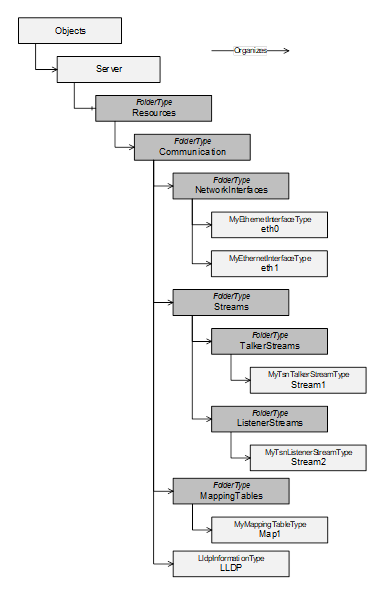
Figure 3 – Instance Entry Points for Network Interfaces, Streams, Mapping Tables and LLDP information
The Resources Object shall be used as the browse entry point for physical and logical resources of the device the Server is running on. It shall reside in the Server Object defined in OPC 10000-5. It can contain a set of Organizes References that point to other Objects representing specific resources. It is formally defined in Table 50.
Table 50 – Resources definition
|
Attribute |
Value |
||
|
BrowseName |
Resources |
||
|
References |
NodeClass |
BrowseName |
Comment |
|
ComponentOf of the Server Object defined in Part 5. |
|||
|
HasTypeDefinition |
ObjectType |
FolderType |
|
|
Organizes |
Object |
Communication |
Defined in 5.4.2 |
|
Conformance Units |
|||
|
BNM Entry Points |
|||
The Communication Object shall be used as the browse entry point for communication related resources of the physical device the Server is running on. It is formally defined in Table 51.
The Communication Object is referenced by an Organizes Reference from the Resources Object defined in 5.4.1.
The Communication Object can include the following subfolders:
- MappingTables
- NetworkInterfaces
- Streams
Additionally, the Communication Object may include the LLDP instance.
It is recommended to keep TSN-Streams and possible future (DetNet-)Flows separated in specific folders.
Table 51 – Communication definition
|
Attribute |
Value |
||
|
BrowseName |
Communication |
||
|
References |
NodeClass |
BrowseName |
Comment |
|
HasTypeDefinition |
ObjectType |
FolderType |
|
|
Organizes |
Object |
MappingTables |
Defined in 5.4.3 |
|
Organizes |
Object |
NetworkInterfaces |
Defined in 5.4.4 |
|
Organizes |
Object |
Streams |
Defined in 5.4.5 |
|
Organizes |
Object |
LLDP |
Defined in 5.4.8 |
|
Conformance Units |
|||
|
BNM Entry Points |
|||
The MappingTables Object shall be used as the browse entry point for mapping tables of priority values and their application labels. It is formally defined in Table 52 – MappingTables definition. All instances of the PriorityMappingTableType shall be referenced from this Object, either directly or indirectly, following hierarchical References.
Table 52 – MappingTables definition
|
Attribute |
Value |
||
|
BrowseName |
MappingTables |
||
|
References |
NodeClass |
BrowseName |
Comment |
|
HasTypeDefinition |
ObjectType |
FolderType |
|
|
Conformance Units |
|||
|
BNM Mapping Entry Points |
|||
The NetworkInterfaces Object shall be used as the browse entry point for network interfaces of the device the Server is running on. It is formally defined in Table 53.
Table 53 – NetworkInterfaces definition
|
Attribute |
Value |
||
|
BrowseName |
NetworkInterfaces |
||
|
References |
NodeClass |
BrowseName |
Comment |
|
HasTypeDefinition |
ObjectType |
FolderType |
|
|
Conformance Units |
|||
|
BNM Entry Points |
|||
The NetworkInterfaces folder is intended to hold instances, which are of IetfBaseNetworkInterfaceType or a subtype of it. However other Objects can be stored within this folder that implement the UA Interface IIetfBaseNetworkInterfaceType.
All Objects of Type IetfBaseNetworkInterfaceType within the NetworkInterfaces folder shall represent either a physical or virtual network interface.
The Streams Object shall be used as the browse entry point for network streams of the device the Server is running on. It is formally defined in Table 54.
Table 54 – Streams definition
|
Attribute |
Value |
||
|
BrowseName |
Streams |
||
|
References |
NodeClass |
BrowseName |
Comment |
|
HasTypeDefinition |
ObjectType |
FolderType |
|
|
Organizes |
Object |
TalkerStreams |
Defined in 5.4.6 |
|
Organizes |
Object |
ListenerStreams |
Defined in 5.4.7 |
|
Conformance Units |
|||
|
BNM TSN Entry Points |
|||
The TalkerStreams Object shall be used as the browse entry point for sending network streams of the device the Server is running on. It is formally defined in Table 55.
Table 55 – TalkerStreams definition
|
Attribute |
Value |
||
|
BrowseName |
TalkerStreams |
||
|
References |
NodeClass |
BrowseName |
Comment |
|
HasTypeDefinition |
ObjectType |
FolderType |
|
|
Conformance Units |
|||
|
BNM TSN Entry Points |
|||
The ListenerStreams Object shall be used as the browse entry point for receiving network streams of the device the Server is running on. It is formally defined in Table 56.
Table 56 – ListenerStreams definition
|
Attribute |
Value |
||
|
BrowseName |
ListenerStreams |
||
|
References |
NodeClass |
BrowseName |
Comment |
|
HasTypeDefinition |
ObjectType |
FolderType |
|
|
Conformance Units |
|||
|
BNM TSN Entry Points |
|||
The LLDP Information Object shall be used as the single browse entry point for all LLDP information represented in the Server running on the device. It is formally defined in Table 57.
Table 57 – LLDP definition
|
Attribute |
Value |
||
|
BrowseName |
LLDP |
||
|
References |
NodeClass |
BrowseName |
Comment |
|
HasTypeDefinition |
ObjectType |
LldpInformationType |
|
|
Conformance Units |
|||
|
BNM IEEE LLDP Info |
|||
The LLDP Object is an instance of Type LldpInformationType and represents the same structure as the YANG container lldp defined in the IEEE 802.1ABcu-2021. This object shall be read-only. The content is filled by the LLDP agent, based on the current configuration and operation. This LLDP agent behaves according to IEEE 802.1AB-2016 and is configured via mechanisms defined in IEEE 802.1AB-2016.
Note: The behaviour of an LLDP agent can be further specified and limited by profiles (either IEEE or OPC). This specification only represents data received and transmitted by this agent and is independent of the agent configuration.
Annex A.4 shows an example for the topology discovery using the information models of two neighbour OPC UA Servers.
The IetfBaseNetworkInterfaceType defines the core set of properties needed to model a network interface based on the definition provided by IETF. Figure 4 illustrates the structure of the IetfBaseNetworkInterfaceType.
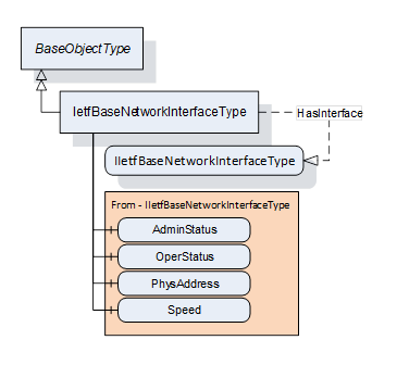
Figure 4 – IetfBaseNetworkInterfaceType
The IetfBaseNetworkInterfaceType is formally defined in Table 58.
Table 58 – IetfBaseNetworkInterfaceType definition
|
Attribute |
Value |
||||
|
BrowseName |
IetfBaseNetworkInterfaceType |
||||
|
IsAbstract |
False |
||||
|
References |
Node |
BrowseName |
DataType |
TypeDefinition |
Other |
|
Subtype of the BaseObjectType |
|||||
|
|
|
|
|
|
|
|
HasInterface |
ObjectType |
IIetfBaseNetworkInterfaceType |
|
|
|
|
Applied from IIetfBaseNetworkInterfaceType (see 5.2.1) |
|||||
|
HasComponent |
Variable |
AdminStatus |
InterfaceAdminStatus |
BaseDataVariableType |
M |
|
HasComponent |
Variable |
OperStatus |
InterfaceOperStatus |
BaseDataVariableType |
M |
|
HasComponent |
Variable |
PhysAddress |
String |
BaseDataVariableType |
O |
|
HasComponent |
Variable |
Speed |
UInt64 |
AnalogUnitType |
M |
|
|
|
|
|
|
|
|
HasLowerLayerInterface |
Object |
<InterfaceName> |
|
BaseObjectType |
OP |
|
Conformance Units |
|||||
|
BNM IETF Interface Base Info |
|||||
The BrowseName of this Object shall be the same as the ifName of the corresponding IETF object (ifName is defined in IETF RFC 2863: The Interfaces Group MIB).
For the formal definition of AdminStatus, OperStatus, PhysAddress and Speed please refer to 5.2.1.
The HasLowerLayerInterface Reference points to an Object implementing the IIetfBaseNetworkInterfaceType used to indicate a hierarchical connection of network interfaces. This is used to indicate the relation e.g. between a VLAN interface and the actual physical interface. A VLAN interface shall additionally implement IVlanIdType.
Each instance of the IetfBaseNetworkInterfaceType shall point to zero or one instance of PriorityMappingTableType or a subtype using a UsesProrityMappingTable Reference or a subtype. The referenced PriorityMappingTable is used for the prioritisation of network messages injected to the network using this network interface. If an instance of type IetfBaseNetworkInterfaceType has no reference to a PriorityMappingTable, the PriorityMappingTable of the next lower layer interface of type IetfBaseNetworkInterfaceType shall be used. An example for this is shown in Annex A.2 for “eth0.100”.
It is recommended that within one network domain that all interfaces should have consistent MappingTables assigned. This ensures consistent use of Quality of Service features within the network.
A network interface is linked for transmission or reception via the BrowseName of the object of type IetfBaseNetworkInterfaceType.
Note: An example for a simplified PubSub connection is shown in Annex A.2.
The components of the IetfBaseNetworkInterfaceType have the Attribute values defined in Table 59.
Table 59 – IetfBaseNetworkInterfaceType Attribute values for child Nodes
|
Source Path |
Value Attribute |
Description Attribute |
||
|
NamespaceUri: http://www.opcfoundation.org/UA/units/un/cefact UnitId: 4337968 |
- |
The components of the IetfBaseNetworkInterfaceType have additional References which are defined in Table 60.
Table 60 – IetfBaseNetworkInterfaceType Additional References
|
SourceBrowsePath |
Reference Type |
Is Forward |
TargetBrowsePath |
|
<InterfaceName> |
HasInterface |
True |
IIetfBaseNetworkInterfaceType |
Instances of the PriorityMappingTableType contains priority mapping information. Figure 5 illustrates the structure of the PriorityMappingTableType.
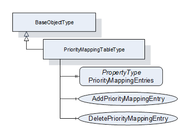
Figure 5 – PriorityMappingTableType
The PriorityMappingTableType is formally defined in Table 61.
Table 61 – PriorityMappingTableType definition
|
Attribute |
Value |
||||
|
BrowseName |
PriorityMappingTableType |
||||
|
IsAbstract |
False |
||||
|
References |
Node |
BrowseName |
DataType |
TypeDefinition |
Other |
|
Subtype of the BaseObjectType defined in OPC 10000-5 |
|||||
|
HasProperty |
Variable |
PriorityMapppingEntries |
PriorityMappingEntryType[] |
PropertyType |
M |
|
HasComponent |
Method |
AddPriorityMappingEntry |
Defined in 5.5.2.3 |
O |
|
|
HasComponent |
Method |
DeletePriorityMappingEntry |
Defined in 5.5.2.4 |
O |
|
|
Conformance Units |
|||||
|
BNM Priority Mapping 2 |
|||||
PriorityMappingEntries represents a list of all instances of PriorityMappingEntryType. For a formal definition see 5.3.2.1. The order of the elements in the array does not have any influence, as elements are indexed via the MappingUri and PriorityLabel.
The combination of QosCategory and PriorityLabel are used as indices into the referenced PriorityMappingTable to look up the priority values. The reference from an IetfBaseNetworkInterface is described in Section 5.5.1. For the sender, the priority values shall be included within the frame, if the according fields are available, i.e., VLAN Tag to use the PCP value and IP header to use the DSCP value. The receiver can use the priority values for internal packet processing.
Note: An example for a simplified PubSub connection is shown in Annex A.2. Within the PubSubConnection, each WriterGroup can contain a QosCategory and DatagramQos structure with a PriorityLabel. For the subscriber side these values are specified on the DataSetReader level.
AddPriorityMappingEntry allows to add an entry to this instance of PriorityMappingTableType.
DeletePriorityMappingEntry allows to delete an entry from this instance of PriorityMappingTableType.
This optional Method allows to add an entry to this instance of PriorityMappingTableType. If the combination of MappingUri and PriorityLabel does not exist yet, the element will be added to the Variable PriorityMappingEntries.
The signature of this Method is specified below. Table 62 and Table 64 specify the Arguments and AddressSpace representation, respectively.
Signature
AddPriorityMappingEntry(
[in] String MappingUri,
[in] String PriorityLabel,
[in] Byte PriorityValue_PCP,
[in] UInt32 PriorityValue_DSCP
);
Table 62 – AddPriorityMappingEntry Method arguments
|
Argument |
Description |
|
MappingUri |
Named identifier of a well-known predefined set of priority labels. |
|
PriorityLabel |
Textual representation of the desired transport priority. |
|
PriorityValue_PCP |
PriorityValue_PCP shall be a value between 0 and 7. |
|
PriorityValue_DSCP |
PriorityValue_DSCP shall be a value between 0 and 63. |
The possible Method result codes are defined in Table 63.
Table 63 – AddPriorityMappingEntry Method result codes
|
ResultCode |
Description |
|
Bad_UserAccessDenied |
The caller is not allowed to add a priority mapping rule. |
|
Bad_InvalidArgument |
One of the arguments is invalid. |
|
Bad_IndexRangeInvalid |
A mapping table entry with MappingUri and PriorityLabel already exists. |
Table 64 – AddPriorityMappingEntry Method AddressSpace definition
|
Attribute |
Value |
||||
|
BrowseName |
AddPriorityMappingEntry |
||||
|
References |
Node Class |
BrowseName |
DataType |
TypeDefinition |
Other |
|
HasProperty |
Variable |
InputArguments |
Argument[] |
PropertyType |
M |
This optional Method allows to delete an entry from this instance of PriorityMappingTableType.
The signature of this Method is specified below. Table 65 and Table 67 specify the Arguments and AddressSpace representation, respectively.
Signature
DeletePriorityMappingEntry(
[in] String MappingUri,
[in] String PriorityLabel
);
Table 65 – DeletePriorityMappingEntry Method arguments
|
Argument |
Description |
|
MappingUri |
Named identifier of a well-known predefined set of priority labels. |
|
PriorityLabel |
Textual representation of the desired transport priority. |
The possible Method result codes are defined in Table 66.
Table 66 – DeletePriorityMappingEntry Method result codes
|
ResultCode |
Description |
|
Bad_UserAccessDenied |
The caller is not allowed to delete the priority mapping rule. |
|
Bad_InvalidState |
The state of this ConnectionConfigurationSetType instance is “Processing”. |
|
Bad_BrowseNameInvalid |
The BrowseName for the mapping entry is invalid. |
Table 67 – DeletePriorityMappingEntry Method AddressSpace definition
|
Attribute |
Value |
||||
|
BrowseName |
DeletePriorityMappingEntry |
||||
|
References |
Node Class |
BrowseName |
DataType |
TypeDefinition |
Other |
|
HasProperty |
Variable |
InputArguments |
Argument[] |
PropertyType |
M |
An instance of the LldpInformationType contains LLDP information collected by an independent LLDP agent. Figure 6 illustrates the structure of the LldpInformationType.
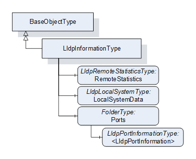
Figure 6 – LldpInformationType
The LldpInformationType is formally defined in Table 68.
Table 68 – LldpInformationType definition
|
Attribute |
Value |
||||
|
BrowseName |
LldpInformationType |
||||
|
IsAbstract |
False |
||||
|
References |
Node |
BrowseName |
DataType |
TypeDefinition |
Other |
|
Subtype of the BaseObjectType |
|||||
|
|
|
|
|
|
|
|
HasComponent |
Object |
RemoteStatistics |
|
LldpRemoteStatisticsType |
O |
|
HasComponent |
Object |
LocalSystemData |
LldpLocalSystemType |
M |
|
|
HasComponent |
Object |
Ports |
FolderType |
M |
|
|
|
|
|
|
|
|
|
Conformance Units |
|||||
|
BNM IEEE LLDP Info |
|||||
LldpInformationType represents the schema of the YANG container lldp in IEEE 802.1ABcu-2021. It models the two entry points for subsequent structures LocalSystemData for all device-related identification and Ports for the port-specific identification and information on neighbour devices.
RemoteStatistics contains a collection of statistics indicating activity and events occurring on neighbour devices.
LocalSystemData represents all device-related identification properties.
Ports is a folder containing one or more instances of LldpPortInformationType that contains information about neighbouring devices seen through that port. The content of Ports is limited to instances of Type LldpPortInformationType.
The components of the LldpInformationType have additional subcomponents, which are defined in Table 69.
Table 69 - LldpInformationType Addtional Components
|
BrowsePath |
References |
NodeClass |
BrowseName |
DataType |
TypeDefinition |
Other |
|
Ports |
Organizes |
Object |
<LldpPortInformation> |
|
LldpPortInformationType |
OP |
The LldpRemoteStatisticsType is formally defined in Table 70.
Table 70 – LldpRemoteStatisticsType definition
|
Attribute |
Value |
||||
|
BrowseName |
LldpRemoteStatisticsType |
||||
|
IsAbstract |
False |
||||
|
References |
Node |
BrowseName |
DataType |
TypeDefinition |
Other |
|
Subtype of the BaseObjectType |
|||||
|
|
|
|
|
|
|
|
HasComponent |
Variable |
LastChangeTime |
UInt32 |
BaseDataVariableType |
M |
|
HasComponent |
Variable |
RemoteInserts |
UInt32 |
BaseDataVariableType |
M |
|
HasComponent |
Variable |
RemoteDeletes |
UInt32 |
BaseDataVariableType |
M |
|
HasComponent |
Variable |
RemoteDrops |
UInt32 |
BaseDataVariableType |
M |
|
HasComponent |
Variable |
RemoteAgeouts |
UInt32 |
BaseDataVariableType |
M |
|
|
|
|
|
|
|
|
Conformance Units |
|||||
|
BNM IEEE LLDP Info |
|||||
LldpRemoteStatisticsType represents the schema of the YANG container remote-statistics in IEEE 802.1ABcu-2021.
LastChangeTime defines the time any remote info changed in the scale of the uptime of the system, as defined in clause 11.5.1 of IEEE Std 802.1AB-2016: lldpV2StatsRemTablesLastChangeTime. The uptime of the system is specified by IETF RFC 3418 in the unit of hundreths of a second.
RemoteInserts defines the number of times new information was inserted into the LldpRemoteSystemsType array, as defined in clause 11.5.1 of IEEE Std 802.1AB-2016: lldpV2StatsRemTablesInserts. When this counter reaches the end of its range, it rolls over to 0.
RemoteDeletes defines the number of times information was deleted from the LldpRemoteSystemsType array, as defined in clause 11.5.1 of IEEE Std 802.1AB-2016: lldpV2StatsRemTablesDeletes. When this counter reaches the end of its range, it rolls over to 0.
RemoteDrops defines the number of times new information could not be inserted into the LldpRemoteSystemsType array because of insufficient resources, as defined in clause 11.5.1 of IEEE Std 802.1AB-2016: lldpV2StatsRemTablesDrops. When this counter reaches the end of its range, it rolls over to 0.
RemoteAgeouts defines the number of times information aged out from the LldpRemoteSystemsType array because the information timeliness interval has expired, as defined in clause 11.5.1 of IEEE Std 802.1AB-2016: lldpV2StatsRemTablesAgeouts. When this counter reaches the end of its range, it rolls over to 0.
The LldpLocalSystemType is formally defined in Table 71.
Table 71 – LldpLocalSystemType definition
|
Attribute |
Value |
||||
|
BrowseName |
LldpLocalSystemType |
||||
|
IsAbstract |
False |
||||
|
References |
Node |
BrowseName |
DataType |
TypeDefinition |
Other |
|
Subtype of the BaseObjectType |
|||||
|
|
|
|
|
|
|
|
HasProperty |
Variable |
ChassisIdSubtype |
ChassisIdSubtype |
PropertyType |
M |
|
HasProperty |
Variable |
ChassisId |
String |
PropertyType |
M |
|
HasProperty |
Variable |
SystemName |
String |
PropertyType |
M |
|
HasProperty |
Variable |
SystemDescription |
String |
PropertyType |
M |
|
HasProperty |
Variable |
SystemCapabilitiesSupported |
LldpSystemCapabilitiesMap |
PropertyType |
O |
|
HasProperty |
Variable |
SystemCapabilitiesEnabled |
LldpSystemCapabilitiesMap |
PropertyType |
O |
|
|
|
|
|
|
|
|
Conformance Units |
|||||
|
BNM IEEE LLDP Info |
|||||
LldpLocalSystemType represents the schema of the YANG container local-system-data in IEEE 802.1ABcu-2021.
ChassisIdSubtype defines type of encoding used to identify the chassis associated with the local system, as defined in clause 8.5.2.2 of IEEE Std 802.1AB-2016.
ChassisId defines the chassis component associated with the local system, as defined in clause 8.5.2.3 of IEEE Std 802.1AB-2016.
SystemName defines the system name of the local system, as defined in clause 8.5.6.2 of IEEE Std 802.1AB-2016.
SystemDescription defines the system description of the local system, as defined in clause 8.5.7.2 of IEEE Std 802.1AB-2016.
SystemCapabilitiesSupported defines the system capabilities that are supported on the local system, as defined in clause 8.5.8.1 of IEEE Std 802.1AB-2016.
SystemCapabilitiesEnabled defines the system capabilities that are enabled on the local system, as defined in clause 8.5.8.2 of IEEE Std 802.1AB-2016.
The LldpPortInformationType is formally defined in Table 72.
Table 72 – LldpPortInformationType definition
|
Attribute |
Value |
||||
|
BrowseName |
LldpPortInformationType |
||||
|
IsAbstract |
False |
||||
|
References |
Node |
BrowseName |
DataType |
TypeDefinition |
Other |
|
Subtype of the BaseObjectType |
|||||
|
|
|
|
|
|
|
|
HasProperty |
Variable |
IetfBaseNetworkInterfaceName |
String |
PropertyType |
M |
|
HasProperty |
Variable |
DestMacAddress |
Byte[6] |
PropertyType |
M |
|
HasProperty |
Variable |
PortIdSubtype |
PortIdSubtype |
PropertyType |
M |
|
HasProperty |
Variable |
PortId |
String |
PropertyType |
M |
|
HasProperty |
Variable |
PortDescription |
String |
PropertyType |
O |
|
HasProperty |
Variable |
ManagementAddressTxPort |
LldpManagementAddressTxPortType[] |
PropertyType |
O |
|
HasComponent |
Object |
RemoteSystemsData |
|
FolderType |
O |
|
|
|
|
|
|
|
|
Conformance Units |
|||||
|
BNM IEEE LLDP Info |
|||||
LldpPortInformationType represents the schema of the YANG list port in IEEE 802.1Abcu-2021.
IetfBaseNetworkInterfaceName points to an object of type IetfBaseNetworkInterfaceType organized in the NetworkInterfaces folder with the value of the String. This link is needed to identify the port component (contained in the local chassis with the LLDP agent) associated with this entry. Annex A.3 visualizes this reference.
DestMacAddress defines the MAC address of this network interface.
PortIdSubtype defines type of encoding used to identify the associated PortId, as defined in clause 8.5.3.2 of IEEE Std 802.1AB-2016.
PortId defines the port component associated with a given port in the local system, as defined in clause 8.5.3.3 of IEEE Std 802.1AB-2016.
PortDescription defines the port description associated with the local system, as defined in clause 8.5.5.2 of IEEE Std 802.1AB-2016.
ManagementAddressTxPort defines the set of ports (represented as a List of Type LldpManagementAddressTxPortType) on which the local system management address instance will be transmitted.
RemoteSystemsData defines the data received on this particular physical network connection. It is a folder containing instances of type LldpRemoteSystemType.
The components of the LldpInformationType have additional subcomponents, which are defined in Table 73.
Table 73 - LldpPortInformationType additional subcomponents
|
BrowsePath |
References |
NodeClass |
BrowseName |
DataType |
TypeDefinition |
Other |
|
RemoteSystemsData |
Organizes |
Object |
<LldpRemoteSystem> |
|
LldpRemoteSystemType |
OP |
The LldpRemoteSystemType is formally defined in Table 74.
Table 74 – LldpRemoteSystemType definition
|
Attribute |
Value |
||||
|
BrowseName |
LldpRemoteSystemType |
||||
|
IsAbstract |
False |
||||
|
References |
Node |
BrowseName |
DataType |
TypeDefinition |
Other |
|
Subtype of the BaseObjectType |
|||||
|
|
|
|
|
|
|
|
HasComponent |
Variable |
TimeMark |
UInt32 |
BaseDataVariableType |
M |
|
HasComponent |
Variable |
RemoteIndex |
UInt32 |
BaseDataVariableType |
M |
|
HasComponent |
Variable |
ChassisIdSubtype |
ChassisIdSubtype |
BaseDataVariableType |
M |
|
HasComponent |
Variable |
ChassisId |
String |
BaseDataVariableType |
M |
|
HasComponent |
Variable |
PortIdSubtype |
PortIdSubtype |
BaseDataVariableType |
M |
|
HasComponent |
Variable |
PortId |
String |
BaseDataVariableType |
M |
|
HasComponent |
Variable |
PortDescription |
String |
BaseDataVariableType |
O |
|
HasComponent |
Variable |
SystemName |
String |
BaseDataVariableType |
O |
|
HasComponent |
Variable |
SystemDescription |
String |
BaseDataVariableType |
O |
|
HasComponent |
Variable |
SystemCapabilitiesSupported |
LldpSystemCapabilitiesMap |
BaseDataVariableType |
O |
|
HasComponent |
Variable |
SystemCapabilitiesEnabled |
LldpSystemCapabilitiesMap |
BaseDataVariableType |
O |
|
HasComponent |
Variable |
RemoteChanges |
Boolean |
BaseDataVariableType |
O |
|
HasComponent |
Variable |
RemoteTooManyNeighbors |
Boolean |
BaseDataVariableType |
O |
|
HasComponent |
Variable |
ManagementAddress |
LldpManagementAddressType[] |
BaseDataVariableType |
O |
|
HasComponent |
Variable |
RemoteUnknownTlv |
LldpTlvType[] |
BaseDataVariableType |
O |
|
|
|
|
|
|
|
|
Conformance Units |
|||||
|
BNM IEEE LLDP Info |
|||||
LldpRemoteSystemType represents the schema of the YANG list remote-systems-data in IEEE 802.1ABcu-2021. These instances are populated based on received LLDP TLVs.
TimeMark defines a TimeFilter for this entry, as defined in IETF RFC 2021 section 6. The units for this time are hundredths of seconds.
RemoteIndex defines an arbitrary local integer value used to identify a remote system, as defined in clause 11.5.1 of IEEE Std 802.1AB-2016: lldpV2RemIndex.
ChassisIdSubtype defines type of encoding used to identify the chassis associated with the remote system, as defined in clause 8.5.2.2 of IEEE Std 802.1AB-2016.
ChassisId defines the chassis component associated with the remote system, as defined in clause 8.5.2.3 of IEEE Std 802.1AB-2016.
PortIdSubtype defines type of encoding used to identify the associated PortId, as defined in clause 8.5.3.2 of IEEE Std 802.1AB-2016.
PortId defines the port component associated with a given port in the remote system, as defined in clause 8.5.3.3 of IEEE Std 802.1AB-2016.
PortDescription defines the port description associated with the remote system, as defined in clause 8.5.5.2 of IEEE Std 802.1AB-2016.
SystemName defines the system name of the remote system, as defined in clause 8.5.6.2 of IEEE Std 802.1AB-2016.
SystemDescription defines the system description of the remote system, as defined in clause 8.5.7.2 of IEEE Std 802.1AB-2016.
SystemCapabilitiesSupported defines the system capabilities are supported on the remote system, as defined in clause 8.5.8.1 of IEEE Std 802.1AB-2016.
SystemCapabilitiesEnabled defines the system capabilities are enabled on the remote system, as defined in clause 8.5.8.2 of IEEE Std 802.1AB-2016.
RemoteChanges Indicates that there are changes in the remote system's data, as determined by the variable remoteChanges, as defined in clause 9.2.5.11 of IEEE Std 802.1AB-2016.
RemoteTooManyNeighbors Indicates that there are too many neighbors as determined by the variable tooManyNeighbors, as defined in clause 9.2.5.15 of IEEE Std 802.1AB-2016.
ManagementAddress defines the Management address information about a particular chassis component (represented as a List of Type LldpManagementAddressType).
RemoteUnknownTlv defines Information about an unrecognized TLV received from a physical network connection.
All values get initialized from the LLDP stack based on received TLVs. If mandatory variables are not initialized due to a non-conforming LLDP stack, the return value for Browse action shall be Bad_NoValue, as defined in OPC 10000-4.
The UsesPriorityMappingTable ReferenceType is a concrete ReferenceType and can be used directly. It is a subtype of NonHierarchicalReferences ReferenceType.
The SourceNode of this ReferenceType shall be an Object implementing the IIetfBaseNetworkInterfaceType or an Object of Type IetfBaseNetworkInterfaceType. Each Node shall be the SourceNode of at most one UsesPriorityMappingTable Reference.
The TargetNode of this ReferenceType shall be an instance of PriorityMappingTableType.
The UsesPriorityMappingTable ReferenceType is formally defined in Table 75.
Table 75 – UsesPriorityMappingTable definition
|
Attributes |
Value |
||
|
BrowseName |
UsesPriorityMappingTable |
||
|
InverseName |
UsedByNetworkInterface |
||
|
Symmetric |
False |
||
|
IsAbstract |
False |
||
|
References |
NodeClass |
BrowseName |
Comment |
|
Subtype of the NonHierarchicalReferences ReferenceType defined in OPC 10000-5 |
|||
|
Conformance Units |
|||
|
BNM Priority Mapping 2 |
|||
The HasLowerLayerInterface ReferenceType is a concrete ReferenceType and can be used directly. It is a subtype of HierarchicalReferences ReferenceType.
The usage of the References is following the YANG modelling approach which is using reference pointers in the YANG-interface nodes to point to other interface nodes in lower or higher layers (“lower-layer-if”, “higher-layer-if”). The YANG Data Model for Interface Management is defined in IETF RFC 8343.
Virtual interfaces shall reference their physical interfaces with the HasLowerLayerInterfaceReferenceType. Annex A contains examples for such hierarchical references.
The SourceNode of this ReferenceType shall be an Object organized in the NetworkInterfaces folder.
The TargetNode of this ReferenceType shall be an Object organized in the NetworkInterfaces folder.
The HasLowerLayerInterface ReferenceType is formally defined in Table 76.
Table 76 – HasLowerLayerInterface definition
|
Attributes |
Value |
||
|
BrowseName |
HasLowerLayerInterface |
||
|
InverseName |
HasHigherLayerInterface |
||
|
Symmetric |
False |
||
|
IsAbstract |
False |
||
|
References |
NodeClass |
BrowseName |
Comment |
|
Subtype of the HierarchicalReferences ReferenceType defined in OPC 10000-5 |
|||
|
Conformance Units |
|||
|
BNM IETF Interface Base Info |
|||
Annex A Modelling Examples (informative)
A.1 Modelling Examples for Network Interfaces
A.1.1 Virtual Network Interfaces
A virtual interfaces configuration can be represented by Objects representing the virtual and the physical network interface instances. HasLowerLayerInterface References point from the Object(s) representing the virtual interface(s) to the Object representing the physical interface. All Objects are of ObjectType IetfBaseNetworkInterfaceType. An example is shown in Figure A-1.
Note: The usage of the References is following the YANG modelling approach which is using reference pointers in the YANG-interface nodes to point to other interface nodes in lower or higher layers (“higher-layer-if”, “lower-layer-if”).
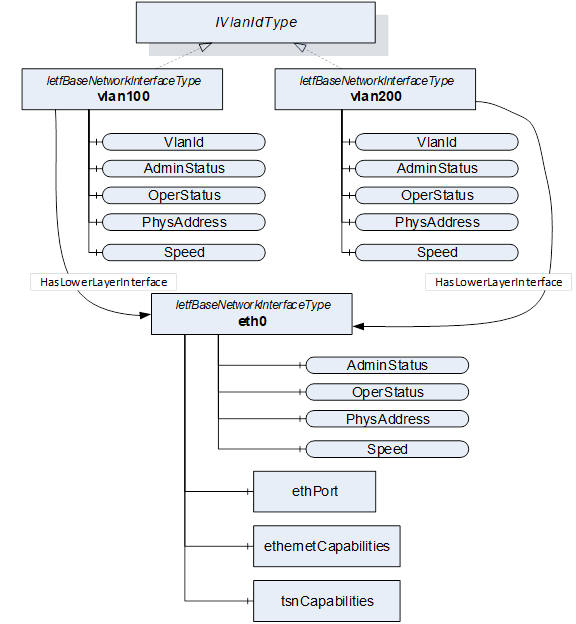
Figure A-1 – Modelling Example for virtual network interfaces
A link aggregation configuration can be represented by Objects representing the logical aggregation and the particular physical interface instances. HasLowerLayerInterface References point from the Object(s) representing the aggregation interface to the Objects representing the physical interfaces. All Objects implement the IIetfBaseNetworkInterfaceType. An example is shown in Figure A-2.
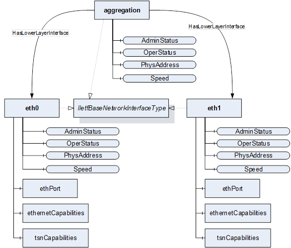
Figure A-2 – Modelling example for link aggregation
A.2 Modelling Examples for PriorityMappingEntries and IetfBaseNetworkInterface
All packets sent via this network interface will use the source address and – in case of VLAN interfaces – VLAN ID as specified by this interface to generate a packet. All packets received via this network interface will use – in case of unicast communication – the destination address and – in case of VLAN interfaces – VLAN ID as specified by the interface to filter incoming packets.
When using PubSub, each PubSubConnection as defined by the PubSubConnectionDataType in Part14 contains the address variable of type NetworkAddressDataType. If the networkInterface String of the NetworkAddressDataType matches the BrowseName of one Object in the NetworkInterfaces folder, it links the transmission or reception and the network interface. An example is shown in Figure A-3.
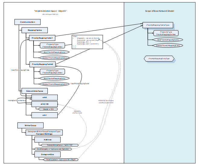
Figure A-3 – Modelling Example for PriorityMappingTableType and IetfBaseNetworkInterface
A.3 Connecting LldpPortInformationType and IetfBaseNetworkInterfaceType
The LldpPortInformationType is connected to the associated Object of type IetfBaseNetworkInterfaceType via the name of the variable IetfBaseNetworkInterfaceName. Figure A-4 shows an example of this reference for the IetfBaseNetworkInterface with the BrowseName eth0.
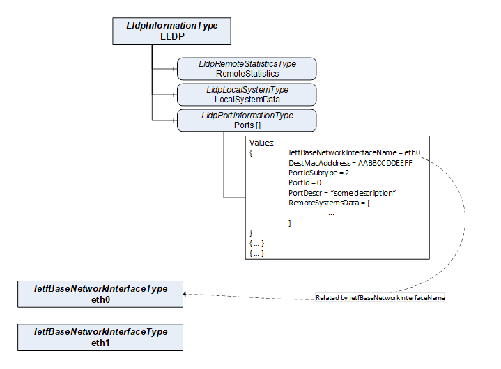
Figure A-4 – Connection between LLDP and IetfInterfaces
A.4 Topology Discovery with LldpRemoteSystems
LLDP exchanges information of the local system and its direct peers in the network through link-local communication. The local systems information of the peers is represented in the remote systems data structure. Figure A-5 shows an example for this connection between two different OPC UA Servers and their representation of the LLDP information. The RemoteSystemsData contains the information of the corresponding LocalSystemsData and PortInformation. For simplicity, this figure does not present all possible variables.
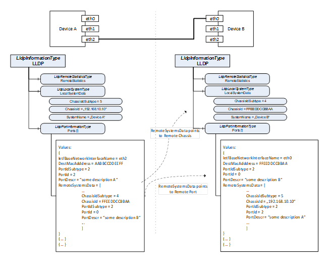
Figure A-5 – Topology Discovery via LLDP
A.5 Usage of BNM in other UA Specifications
A.5.1 Usage of BNM for PubSub over TSN
An example using the BNM for PubSub over TSN is shown in Figure A-6.
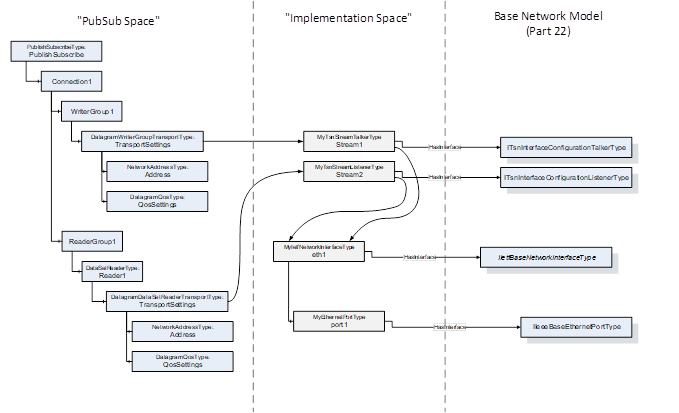
Figure A-6 – Possible Integration of BNM into PubSub
A.5.2 Usage of BNM in PROFINET Companion Spec
An example is shown in Figure A-7.
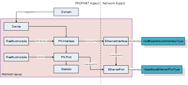
Figure A-7 – Recommended Integration of BNM into Companion Spec exemplified by PROFINET
___________