|
|
OPC UA Specification |
|
OPC 10000-4 |
|
|
OPC Unified Architecture Part 4: Services
Release 1.05.04 2024-10-15
|

|
|
OPC UA Specification |
|
OPC 10000-4 |
|
|
OPC Unified Architecture Part 4: Services
Release 1.05.04 2024-10-15
|
|
Specification Type: |
Industry Standard Specification |
Comments: |
|
|
|
|
|
|
|
Title: |
OPC Unified Architecture Part 4: Services |
Date: |
2024-10-15 |
|
|
|
|
|
|
Version: |
Release 1.05.04 |
Software: |
MS-Word |
|
|
|
Source: |
OPC 10000-4 - UA Specification Part 4 - Services.docx |
|
|
|
|
|
|
Author: |
OPC Foundation |
Status: |
Release |
|
|
|
|
|
CONTENTS
3 Terms, definitions, abbreviated terms and conventions
3.3 Conventions for Service definitions
4.2 Request/response Service procedures
5.2 Service request and response header
5.8 NodeManagement Service Set
5.9.4 TranslateBrowsePathsToNodeIds
5.13 MonitoredItem Service Set
6.1.2 Obtaining and installing an Application Instance Certificate
6.1.3 Determining if a Certificate is trusted
6.1.4 Creating a SecureChannel
6.1.7 Continuous security checks
6.2.2 Indirect handshake with an Identity Provider
6.2.3 Direct handshake with an Identity Provider
6.3 Session-less Service invocation
6.5.4 Auditing for Discovery Service Set
6.5.5 Auditing for SecureChannel Service Set
6.5.6 Auditing for Session Service Set
6.5.7 Auditing for NodeManagement Service Set
6.5.8 Auditing for Attribute Service Set
6.5.9 Auditing for Method Service Set
6.5.10 Auditing for View, Query, MonitoredItem and Subscription Service Set
6.6.5 Manually Forcing Failover
6.7 Re-establishing connections
7 Common parameter type definitions
7.3 ApplicationInstanceCertificate
7.7.4 FilterOperand parameters
7.11.5 StatusCode assigned to a value
7.13 DiscoveryConfiguration parameters
7.13.2 MdnsDiscoveryConfiguration
7.22 MonitoringFilter parameters
7.24 NodeAttributes parameters
7.24.2 ObjectAttributes parameter
7.24.3 VariableAttributes parameter
7.24.4 MethodAttributes parameter
7.24.5 ObjectTypeAttributes parameter
7.24.6 VariableTypeAttributes parameter
7.24.7 ReferenceTypeAttributes parameter
7.24.8 DataTypeAttributes parameter
7.24.9 ViewAttributes parameter
7.24.10 GenericAttributes parameter
7.25 NotificationData parameters
7.25.2 DataChangeNotification parameter
7.25.3 EventNotificationList parameter
7.25.4 StatusChangeNotification parameter
7.36 SessionAuthenticationToken
7.38 SignedSoftwareCertificate
7.41 UserIdentityToken parameters
7.41.2 Token Encryption and Proof of Possession
Annex A (informative) BNF definitions
Annex B (informative) ContentFilter and Query examples
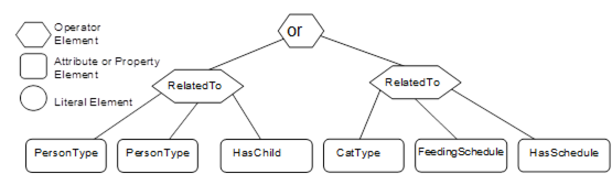
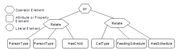
B.1 Simple ContentFilter examples
B.2 Complex Examples of Query Filters
FIGURES
Figure 1 – Discovery Service Set........................................................... 5
Figure 2 – SecureChannel Service Set.................................................... 5
Figure 3 – Session Service Set.............................................................. 5
Figure 4 – NodeManagement Service Set................................................ 6
Figure 5 – View Service Set.................................................................. 6
Figure 6 – Attribute Service Set............................................................. 7
Figure 7 – Method Service Set............................................................... 7
Figure 8 – MonitoredItem and Subscription Service Sets............................. 8
Figure 9 – Discovery process............................................................... 11
Figure 10 – Using a Gateway Server..................................................... 16
Figure 11 – The Registration Process – Manually Launched Servers........... 17
Figure 12 – The Registration Process – Automatically Launched Servers..... 17
Figure 13 – SecureChannel and Session Services................................... 20
Figure 14 – Multiplexing users on a Session........................................... 26
Figure 15 – MonitoredItem model......................................................... 63
Figure 16 – Typical delay in change detection......................................... 65
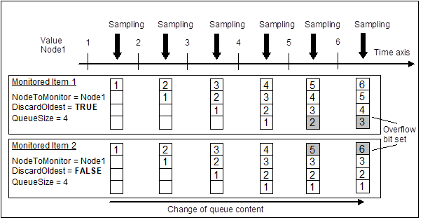
Figure 17 – Queue overflow handling.................................................... 66
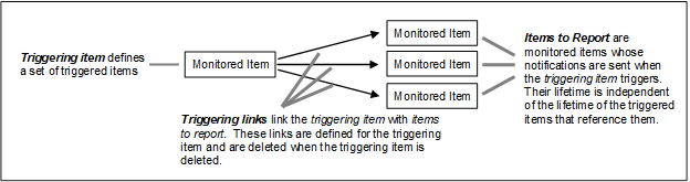
Figure 18 – Triggering model............................................................... 67
Figure 19 – Obtaining and installing an Application Instance Certificate....... 92
Figure 20 – Determining if an Application Instance Certificate is trusted....... 96
Figure 21 – Establishing a SecureChannel............................................. 97
Figure 22 – Establishing a Session....................................................... 98
Figure 23 – Impersonating a User......................................................... 99
Figure 24 – Indirect handshake with an Identity Provider......................... 100
Figure 25 – Direct handshake with an Identity Provider........................... 101
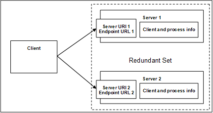
Figure 26 – Transparent Redundancy setup example.............................. 107
Figure 27 – Non-Transparent Redundancy setup................................... 108
Figure 28 – Client Start-up steps........................................................ 111
Figure 29 – Cold Failover.................................................................. 112
Figure 30 – Warm Failover................................................................ 113
Figure 31 – Hot Failover.................................................................... 114
Figure 32 – HotAndMirrored Failover................................................... 115
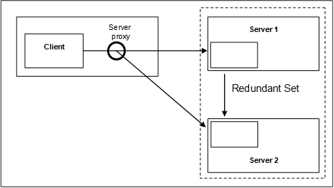
Figure 33 – Server proxy for Redundancy............................................. 115
Figure 34 – Transparent network Redundancy....................................... 116
Figure 35 – Non-transparent network Redundancy................................. 117
Figure 36 – Reconnect sequence........................................................ 118
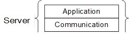
Figure 37 – Logical layers of a Server.................................................. 159
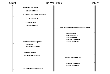
Figure 38 – Obtaining a SessionAuthenticationToken.............................. 159
Figure 39 – EncryptedSecret layout..................................................... 168
Figure B.1 – Filter logic tree example.................................................. 178
Figure B.2 – Filter logic tree example.................................................. 179
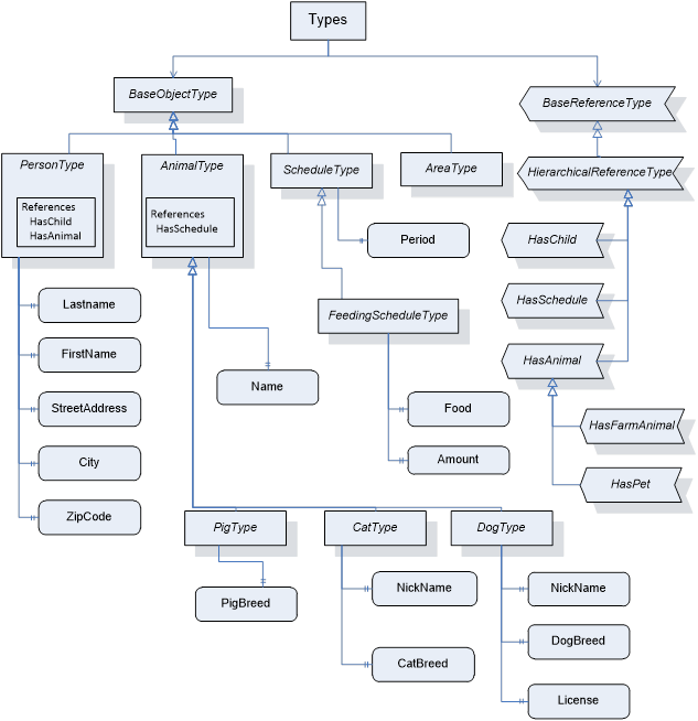
Figure B.3 – Example Type Nodes...................................................... 181
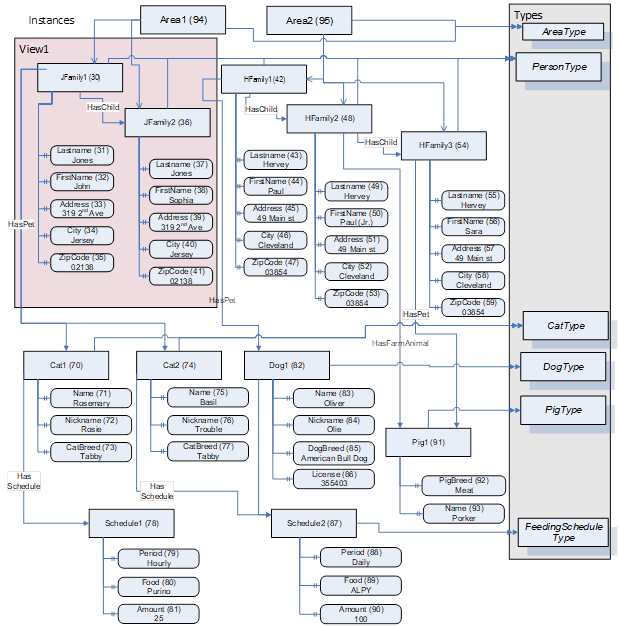
Figure B.4 – Example Instance Nodes................................................. 182
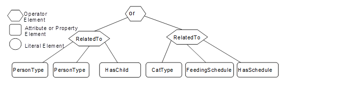
Figure B.5 – Example 1 Filter............................................................. 183
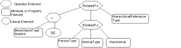
Figure B.6 – Example 2 filter logic tree................................................. 185
Figure B.7 – Example 3 filter logic tree................................................. 186
Figure B.8 – Example 4 filter logic tree................................................. 188
Figure B.9 – Example 5 filter logic tree................................................. 189
Figure B.10 – Example 6 filter logic tree............................................... 190
Figure B.11 – Example 7 filter logic tree............................................... 192
Figure B.12 – Example 8 filter logic tree............................................... 193
Figure B.13 – Example 9 filter logic tree............................................... 195
TABLES
Table 1 – Service definition table........................................................... 4
Table 2 – Parameter Types defined in OPC 10000-3.................................. 4
Table 3 – FindServers Service Parameters............................................. 13
Table 4 – FindServersOnNetwork Service Parameters.............................. 14
Table 5 – GetEndpoints Service Parameters........................................... 16
Table 6 – RegisterServer Service Parameters......................................... 18
Table 7 – RegisterServer Service Result Codes...................................... 18
Table 8 – RegisterServer2................................................................... 19
Table 9 – RegisterServer2 Service Result Codes..................................... 19
Table 10 – RegisterServer2 Operation Level Result Codes........................ 19
Table 11 – OpenSecureChannel Service Parameters................................ 22
Table 12 – OpenSecureChannel Service Result Codes............................. 23
Table 13 – CloseSecureChannel Service Parameters............................... 24
Table 14 – CloseSecureChannel Service Result Codes............................. 24
Table 15 – CreateSession Service Parameters........................................ 27
Table 16 – CreateSession Service Result Codes..................................... 28
Table 17 – ActivateSession Service Parameters...................................... 30
Table 18 – ActivateSession Service Result Codes................................... 31
Table 19 – CloseSession Service Parameters......................................... 31
Table 20 – CloseSession Service Result Codes....................................... 31
Table 21 – Cancel Service Parameters.................................................. 32
Table 22 – AddNodes Service Parameters.............................................. 33
Table 23 – AddNodes Service Result Codes........................................... 33
Table 24 – AddNodes Operation Level Result Codes................................ 34
Table 25 – AddReferences Service Parameters....................................... 35
Table 26 – AddReferences Service Result Codes.................................... 35
Table 27 – AddReferences Operation Level Result Codes......................... 35
Table 28 – DeleteNodes Service Parameters.......................................... 36
Table 29 – DeleteNodes Service Result Codes........................................ 36
Table 30 – DeleteNodes Operation Level Result Codes............................ 37
Table 31 – DeleteReferences Service Parameters................................... 37
Table 32 – DeleteReferences Service Result Codes................................. 37
Table 33 – DeleteReferences Operation Level Result Codes...................... 38
Table 34 – Browse Service Parameters................................................. 39
Table 35 – Browse Service Result Codes............................................... 40
Table 36 – Browse Operation Level Result Codes.................................... 40
Table 37 – BrowseNext Service Parameters........................................... 41
Table 38 – BrowseNext Service Result Codes......................................... 41
Table 39 – BrowseNext Operation Level Result Codes.............................. 42
Table 40 – TranslateBrowsePathsToNodeIds Service Parameters............... 43
Table 41 – TranslateBrowsePathsToNodeIds Service Result Codes............ 43
Table 42 – TranslateBrowsePathsToNodeIds Operation Level Result Codes. 44
Table 43 – RegisterNodes Service Parameters........................................ 44
Table 44 – RegisterNodes Service Result Codes..................................... 45
Table 45 – UnregisterNodes Service Parameters..................................... 45
Table 46 – UnregisterNodes Service Result Codes.................................. 45
Table 47 – QueryFirst Request Parameters............................................ 48
Table 48 – QueryFirst Response Parameters.......................................... 49
Table 49 – QueryFirst Service Result Codes........................................... 50
Table 50 – QueryFirst Operation Level Result Codes................................ 50
Table 51 – QueryNext Service Parameters............................................. 51
Table 52 – QueryNext Service Result Codes........................................... 51
Table 53 – Read Service Parameters.................................................... 52
Table 54 – Read Service Result Codes.................................................. 52
Table 55 – Read Operation Level Result Codes....................................... 53
Table 56 – HistoryRead Service Parameters........................................... 54
Table 57 – HistoryRead Service Result Codes........................................ 56
Table 58 – HistoryRead Operation Level Result Codes............................. 56
Table 59 – Write Service Parameters.................................................... 57
Table 60 – Write Service Result Codes.................................................. 58
Table 61 – Write Operation Level Result Codes....................................... 58
Table 62 – HistoryUpdate Service Parameters........................................ 59
Table 63 – HistoryUpdate Service Result Codes...................................... 59
Table 64 – HistoryUpdate Operation Level Result Codes........................... 59
Table 65 – Call Service Parameters...................................................... 61
Table 66 – Call Service Result Codes.................................................... 62
Table 67 – Call Operation Level Result Codes........................................ 62
Table 68 – Call Input Argument Result Codes......................................... 62
Table 69 – CreateMonitoredItems Service Parameters.............................. 69
Table 70 – CreateMonitoredItems Service Result Codes........................... 69
Table 71 – CreateMonitoredItems Operation Level Result Codes................ 70
Table 72 – ModifyMonitoredItems Service Parameters.............................. 71
Table 73 – ModifyMonitoredItems Service Result Codes........................... 71
Table 74 – ModifyMonitoredItems Operation Level Result Codes................ 72
Table 75 – SetMonitoringMode Service Parameters................................. 72
Table 76 – SetMonitoringMode Service Result Codes............................... 72
Table 77 – SetMonitoringMode Operation Level Result Codes.................... 72
Table 78 – SetTriggering Service Parameters......................................... 73
Table 79 – SetTriggering Service Result Codes....................................... 73
Table 80 – SetTriggering Operation Level Result Codes............................ 74
Table 81 – DeleteMonitoredItems Service Parameters.............................. 74
Table 82 – DeleteMonitoredItems Service Result Codes........................... 74
Table 83 – DeleteMonitoredItems Operation Level Result Codes................ 74
Table 84 – Subscription States............................................................. 77
Table 85 – Subscription State Table...................................................... 78
Table 86 – State variables and parameters............................................. 80
Table 87 – Functions.......................................................................... 81
Table 88 – CreateSubscription Service Parameters.................................. 82
Table 89 – CreateSubscription Service Result Codes............................... 83
Table 90 – ModifySubscription Service Parameters.................................. 84
Table 91 – ModifySubscription Service Result Codes............................... 84
Table 92 – SetPublishingMode Service Parameters.................................. 85
Table 93 – SetPublishingMode Service Result Codes............................... 85
Table 94 – SetPublishingMode Operation Level Result Codes.................... 86
Table 95 – Publish Service Parameters................................................. 87
Table 96 – Publish Service Result Codes............................................... 87
Table 97 – Publish Operation Level Result Codes.................................... 88
Table 98 – Republish Service Parameters.............................................. 88
Table 99 – Republish Service Result Codes............................................ 88
Table 100 – TransferSubscriptions Service Parameters............................ 89
Table 101 – TransferSubscriptions Service Result Codes.......................... 89
Table 102 – TransferSubscriptions Operation Level Result Codes............... 90
Table 103 – DeleteSubscriptions Service Parameters............................... 90
Table 104 – DeleteSubscriptions Service Result Codes............................ 90
Table 105 – DeleteSubscriptions Operation Level Result Codes................. 90
Table 106 – Certificate validation steps................................................. 94
Table 107 – SessionlessInvoke Service Parameters............................... 102
Table 108 – SessionlessInvoke Service Result Codes............................. 103
Table 109 – ServiceLevel ranges........................................................ 109
Table 110 – Server Failover modes..................................................... 110
Table 111 – Redundancy Failover actions............................................. 111
Table 112 – AdditionalParametersType................................................ 121
Table 113 – ApplicationDescription..................................................... 121
Table 114 – ApplicationInstanceCertificate........................................... 122
Table 115 – ApplicationType values.................................................... 122
Table 116 – BrowseDirection values.................................................... 122
Table 117 – BrowseResult................................................................. 123
Table 118 – ContentFilter structure..................................................... 123
Table 119 – ContentFilterResult structure............................................. 124
Table 120 – ContentFilterResult Result Codes....................................... 124
Table 121 – ContentFilterResult Operand Result Codes.......................... 124
Table 122 – Basic FilterOperator definition........................................... 125
Table 123 – Complex FilterOperator definition....................................... 127
Table 124 – Wildcard characters......................................................... 128
Table 125 – Conversion rules............................................................. 129
Table 126 – Data Precedence rules..................................................... 130
Table 127 – Logical AND Truth table................................................... 130
Table 128 – Logical OR Truth table..................................................... 131
Table 129 – FilterOperand parameter TypeIds....................................... 131
Table 130 – ElementOperand............................................................. 131
Table 131 – LiteralOperand............................................................... 131
Table 132 – AttributeOperand............................................................ 132
Table 133 – SimpleAttributeOperand................................................... 132
Table 134 – DataChangeTrigger values............................................... 133
Table 135 – DataValue..................................................................... 134
Table 136 – DiagnosticInfo................................................................ 136
Table 137 – DiscoveryConfiguration parameterTypeIds........................... 136
Table 138 – MdnsDiscoveryConfiguration............................................. 137
Table 139 – EndpointDescription........................................................ 137
Table 140 – EphemeralKeyType......................................................... 138
Table 141 – ExpandedNodeId............................................................ 138
Table 142 – ExtensibleParameter base type.......................................... 138
Table 143 – MessageSecurityMode values........................................... 139
Table 144 – MonitoringParameters...................................................... 140
Table 145 – MonitoringFilter parameterTypeIds..................................... 141
Table 146 – DataChangeFilter............................................................ 141
Table 147 – EventFilter structure........................................................ 143
Table 148 – EventFilterResult structure................................................ 143
Table 149 – EventFilterResult Result Codes......................................... 143
Table 150 – AggregateFilter structure.................................................. 144
Table 151 – AggregateFilterResult structure......................................... 144
Table 152 – MonitoringMode values.................................................... 145
Table 153 – NodeAttributes parameterTypeIds...................................... 145
Table 154 – Bit mask for specified Attributes......................................... 146
Table 155 – ObjectAttributes.............................................................. 146
Table 156 – VariableAttributes........................................................... 147
Table 157 – MethodAttributes............................................................. 147
Table 158 – ObjectTypeAttributes....................................................... 147
Table 159 – VariableTypeAttributes..................................................... 148
Table 160 – ReferenceTypeAttributes.................................................. 148
Table 161 – DataTypeAttributes.......................................................... 148
Table 162 – ViewAttributes................................................................ 149
Table 163 – GenericAttributes............................................................ 149
Table 164 – NotificationData parameterTypeIds..................................... 149
Table 165 – DataChangeNotification.................................................... 150
Table 166 – EventNotificationList........................................................ 150
Table 167 – StatusChangeNotification................................................. 151
Table 168 – NotificationMessage........................................................ 151
Table 169 – NumericRange............................................................... 152
Table 170 – QueryDataSet................................................................ 152
Table 171 – ReadValueId.................................................................. 153
Table 172 – ReferenceDescription...................................................... 153
Table 173 – RelativePath.................................................................. 154
Table 174 – RegisteredServer............................................................ 155
Table 175 – RequestHeader.............................................................. 156
Table 176 – ResponseHeader............................................................ 158
Table 177 – ServiceFault................................................................... 158
Table 178 – SignatureData................................................................ 160
Table 179 – SignedSoftwareCertificate................................................ 160
Table 180 – StatusCode bit assignments.............................................. 161
Table 181 – DataValue InfoBits.......................................................... 162
Table 182 – Common Service Result Codes.......................................... 163
Table 183 – Common Operation Level Result Codes.............................. 165
Table 184 – TimestampsToReturn values............................................. 166
Table 185 – UserIdentityToken parameterTypeIds.................................. 166
Table 186 – Legacy UserIdentityToken Encrypted Token Secret Format..... 168
Table 187 – EncryptedSecret layout.................................................... 169
Table 188 – EncryptedSecret DataTypes.............................................. 169
Table 189 – RsaEncryptedSecret structure........................................... 170
Table 190 – EccEncryptedSecret Layout.............................................. 171
Table 191 – AnonymousIdentityToken.................................................. 171
Table 192 – UserNameIdentityToken................................................... 172
Table 193 – EncryptionAlgorithm selection............................................ 172
Table 194 – X.509 v3 Identity Token.................................................... 173
Table 195 – IssuedIdentityToken........................................................ 173
Table 196 – UserTokenPolicy............................................................. 174
Table 197 – UserTokenType values..................................................... 174
Table 198 – ViewDescription.............................................................. 175
Table A.1 – RelativePath................................................................... 176
Table A.2 – RelativePath Examples..................................................... 177
Table B.1 – ContentFilter example...................................................... 179
Table B.2 – ContentFilter example...................................................... 179
Table B.3 – Example 1 NodeTypeDescription........................................ 183
Table B.4 – Example 1 ContentFilter................................................... 183
Table B.5 – Example 1 QueryDataSets................................................ 184
Table B.6 – Example 2 NodeTypeDescription........................................ 184
Table B.7 – Example 2 ContentFilter................................................... 185
Table B.8 – Example 2 QueryDataSets................................................ 185
Table B.9 – Example 3 - NodeTypeDescription...................................... 186
Table B.10 – Example 3 ContentFilter.................................................. 187
Table B.11 – Example 3 QueryDataSets............................................... 187
Table B.12 – Example 4 NodeTypeDescription...................................... 188
Table B.13 – Example 4 ContentFilter.................................................. 188
Table B.14 – Example 4 QueryDataSets............................................... 188
Table B.15 – Example 5 NodeTypeDescription...................................... 189
Table B.16 – Example 5 ContentFilter.................................................. 189
Table B.17 – Example 5 QueryDataSets............................................... 189
Table B.18 – Example 6 NodeTypeDescription...................................... 190
Table B.19 – Example 6 ContentFilter.................................................. 190
Table B.20 – Example 6 QueryDataSets............................................... 190
Table B.21 – Example 6 QueryDataSets without additional information....... 191
Table B.22 – Example 7 NodeTypeDescription...................................... 191
Table B.23 – Example 7 ContentFilter.................................................. 192
Table B.24 – Example 7 QueryDataSets............................................... 192
Table B.25 – Example 8 NodeTypeDescription...................................... 193
Table B.26 – Example 8 ContentFilter.................................................. 194
Table B.27 – Example 8 QueryDataSets............................................... 194
Table B.28 – Example 9 NodeTypeDescription...................................... 194
Table B.29 – Example 9 ContentFilter.................................................. 195
Table B.30 – Example 9 QueryDataSets............................................... 195
____________
UNIFIED ARCHITECTURE –
This specification is the specification for developers of OPC UA applications. The specification is a result of an analysis and design process to develop a standard interface to facilitate the development of applications by multiple vendors that shall inter-operate seamlessly together.
Copyright © 2006-2024, OPC Foundation, Inc.
COPYRIGHT RESTRICTIONS
Any unauthorized use of this specification may violate copyright laws, trademark laws, and communications regulations and statutes. This document contains information which is protected by copyright. All Rights Reserved. No part of this work covered by copyright herein may be reproduced or used in any form or by any means--graphic, electronic, or mechanical, including photocopying, recording, taping, or information storage and retrieval systems--without permission of the copyright owner.
OPC Foundation members and non-members are prohibited from copying and redistributing this specification. All copies must be obtained on an individual basis, directly from the OPC Foundation Web site http://www.opcfoundation.org.
PATENTS
The attention of adopters is directed to the possibility that compliance with or adoption of OPC specifications may require use of an invention covered by patent rights. OPC shall not be responsible for identifying patents for which a license may be required by any OPC specification, or for conducting legal inquiries into the legal validity or scope of those patents that are brought to its attention. OPC specifications are prospective and advisory only. Prospective users are responsible for protecting themselves against liability for infringement of patents.
WARRANTY AND LIABILITY DISCLAIMERS
WHILE THIS PUBLICATION IS BELIEVED TO BE ACCURATE, IT IS PROVIDED "AS IS" AND MAY CONTAIN ERRORS OR MISPRINTS. THE OPC FOUDATION MAKES NO WARRANTY OF ANY KIND, EXPRESSED OR IMPLIED, WITH REGARD TO THIS PUBLICATION, INCLUDING BUT NOT LIMITED TO ANY WARRANTY OF TITLE OR OWNERSHIP, IMPLIED WARRANTY OF MERCHANTABILITY OR WARRANTY OF FITNESS FOR A PARTICULAR PURPOSE OR USE. IN NO EVENT SHALL THE OPC FOUNDATION BE LIABLE FOR ERRORS CONTAINED HEREIN OR FOR DIRECT, INDIRECT, INCIDENTAL, SPECIAL, CONSEQUENTIAL, RELIANCE OR COVER DAMAGES, INCLUDING LOSS OF PROFITS, REVENUE, DATA OR USE, INCURRED BY ANY USER OR ANY THIRD PARTY IN CONNECTION WITH THE FURNISHING, PERFORMANCE, OR USE OF THIS MATERIAL, EVEN IF ADVISED OF THE POSSIBILITY OF SUCH DAMAGES.
The entire risk as to the quality and performance of software developed using this specification is borne by you.
RESTRICTED RIGHTS LEGEND
This Specification is provided with Restricted Rights. Use, duplication or disclosure by the U.S. government is subject to restrictions as set forth in (a) this Agreement pursuant to DFARs 227.7202-3(a); (b) subparagraph (c)(1)(i) of the Rights in Technical Data and Computer Software clause at DFARs 252.227-7013; or (c) the Commercial Computer Software Restricted Rights clause at FAR 52.227-19 subdivision (c)(1) and (2), as applicable. Contractor / manufacturer are the OPC Foundation, 16101 N. 82nd Street, Suite 3B, Scottsdale, AZ, 85260-1830.
COMPLIANCE
The OPC Foundation shall at all times be the sole entity that may authorize developers, suppliers and sellers of hardware and software to use certification marks, trademarks or other special designations to indicate compliance with these materials. Products developed using this specification may claim compliance or conformance with this specification if and only if the software satisfactorily meets the certification requirements set by the OPC Foundation. Products that do not meet these requirements may claim only that the product was based on this specification and must not claim compliance or conformance with this specification.
Trademarks
Most computer and software brand names have trademarks or registered trademarks. The individual trademarks have not been listed here.
GENERAL PROVISIONS
Should any provision of this Agreement be held to be void, invalid, unenforceable or illegal by a court, the validity and enforceability of the other provisions shall not be affected thereby.
This Agreement shall be governed by and construed under the laws of the State of Minnesota, excluding its choice or law rules.
This Agreement embodies the entire understanding between the parties with respect to, and supersedes any prior understanding or agreement (oral or written) relating to, this specification.
ISSUE REPORTING
The OPC Foundation strives to maintain the highest quality standards for its published specifications, hence they undergo constant review and refinement. Readers are encouraged to report any issues and view any existing errata here: http://www.opcfoundation.org/errataH
Revision 1.05.04 Highlights
The following table includes the Mantis issues resolved with this revision.
|
Mantis ID |
Scope |
Summary |
Resolution |
|
Feature |
External localization of Event Messages |
Add support for special locales ‘mul’ and ‘qst’ defined in OPC 10000-3. |
|
|
Errata |
EndpointUrl check in CreateSession |
Removed the recommendation to check the hostname of the EndpointUrl used by the Client and to issue a AuditUrlMismatchEventType. |
|
|
Errata |
Status for not supported Methods |
Added Bad_NotSupported as operation level result if a Method is not supported for an Object instance. |
|
|
Clarification |
Subscription State Table |
Changed SubscriptionAssignedToClient to SubscriptionAssignedToSession. |
|
|
Clarification |
RelativePath ReferenceTypeId |
Clarified not specified is null value |
|
|
Clarification |
KeyData for RsaEncryptedSecret |
Enhanced description for RsaEncryptedSecret KeyData createion. |
|
|
Clarification |
User for TransferSubscription |
Clarified requirements for checking ClientUserId for TransferSubscription |
|
|
Clarification |
Detection of EncryptedSecret |
Clarified logic to detect an EncrytpedSecret format for user token encryption |
|
|
Clarification |
CreateSession serverEndpoints verification |
Clarified that compare of list is done only for used transportProfileUri and compare is only done if GetEndpoints results used for endpoint selection |
|
|
Errata |
Bad_TooManySubscriptions in TransferSubscriptions |
Added Bad_TooManySubscriptions as operation level result code for TransferSubscriptions |
|
|
Errata |
Client Certificate use |
Added explicit requirement to verify Client Certificate before it is used |
|
|
Errata |
Nonce length requirement |
Nonce length must be between 32 and 128 bytes inclusive. |
OPC Unified Architecture
Part 4: Services Specification
This part of OPC 10000 defines the OPC Unified Architecture (OPC UA) Services. The Services defined are the collection of abstract Remote Procedure Calls (RPC) that are implemented by OPC UA Servers and called by OPC UA Clients. All interactions between OPC UA Clients and Servers occur via these Services. The defined Services are considered abstract because no particular RPC mechanism for implementation is defined in this document. OPC 10000-6 specifies one or more concrete mappings supported for implementation. For example, one mapping in OPC 10000-6 is to UA-TCP UA-SC UA-Binary. In that case the Services described in this document appear as OPC UA Binary encoded payload, secured with OPC UA Secure Conversation and transported via OPC UA TCP.
Not all OPC UA Servers will need to implement all of the defined Services. OPC 10000-7 defines the Profiles that dictate which Services need to be implemented in order to be compliant with a particular Profile.
The following documents, in whole or in part, are normatively referenced in this document and are indispensable for its application. For dated references, only the edition cited applies. For undated references, the latest edition of the referenced document (including any amendments and errata) applies.
OPC 10000-1: OPC Unified Architecture - Part 1: Overview and Concepts
http://www.opcfoundation.org/UA/Part1/
OPC 10000-2: OPC Unified Architecture - Part 2: Security Model
http://www.opcfoundation.org/UA/Part2/
OPC 10000-3: OPC Unified Architecture - Part 3: Address Space Model
http://www.opcfoundation.org/UA/Part3/
OPC 10000-5: OPC Unified Architecture - Part 5: Information Model
http://www.opcfoundation.org/UA/Part5/
OPC 10000-6: OPC Unified Architecture - Part 6: Mappings
http://www.opcfoundation.org/UA/Part6/
OPC 10000-7: OPC Unified Architecture - Part 7: Profiles
http://www.opcfoundation.org/UA/Part7/
OPC 10000-8: OPC Unified Architecture - Part 8: Data Access
http://www.opcfoundation.org/UA/Part8/
OPC 10000-9: OPC Unified Architecture - Part 9: Alarms and Conditions
http://www.opcfoundation.org/UA/Part9/
OPC 10000-11: OPC Unified Architecture - Part 11: Historical Access
http://www.opcfoundation.org/UA/Part11/
OPC 10000-12: OPC Unified Architecture - Part 12: Discovery
http://www.opcfoundation.org/UA/Part12/
OPC 10000-13: OPC Unified Architecture - Part 13: Aggregates
http://www.opcfoundation.org/UA/Part13/
OPC 10000-18: OPC Unified Architecture - Part 18: Role-Based Security
http://www.opcfoundation.org/UA/Part18/
For the purposes of this document, the terms and definitions given in OPC 10000-1, OPC 10000-2, OPC 10000-3, and the following apply.
3.1.1
Active Server
Server which is currently sourcing information
Note 1 to entry: In OPC UA redundant systems, an Active Server is the Server that a Client is using as the source of data.
3.1.2
Deadband
permitted range for value changes that will not trigger a data change Notification
Note 1 to entry: Deadband can be applied as a filter when subscribing to Variables and is used to keep noisy signals from updating the Client unnecessarily. This document defines AbsoluteDeadband as a common filter. OPC 10000-8 defines an additional Deadband filter.
3.1.3
DiscoveryEndpoint
Endpoint that allows Clients access to Discovery Services without security
Note 1 to entry: A DiscoveryEndpoint allows access to Discovery Services without a Session and without message security.
3.1.4
Endpoint
physical address available on a network that allows Clients to access one or more Services provided by a Server
Note 1 to entry: Each Server may have multiple Endpoints. Each Endpoint includes a HostName.
3.1.5
EphemeralKey
public-private key pair generated for each execution of a key establishment process.
Note 1 to entry: EphemeralKeys are necessary when using ECC based SecurityPolicies.
3.1.6
Failed Server
Server that is not operational.
Note 1 to entry: In OPC UA redundant system, a Failed Server is a Server that is unavailable or is not able to serve data.
3.1.7
Failover
act of switching the source or target of information.
Note 1 to entry: In OPC UA redundant systems, a Failover is the act of a Client switching away from a failed or degraded Server to another Server in the redundant set (Server failover). In some cases a Client may have no knowledge of a Failover action occurring (transparent redundancy). A Client failover is the act of an alternate Client replacing an existing failed or degraded Client connection to a Server.
3.1.8
Gateway Server
Server that acts as an intermediary for one or more Servers
Note 1 to entry: Gateway Servers may be deployed to limit external access, provide protocol conversion or to provide features that the underlying Servers do not support.
3.1.9
HostName
unique identifier for a machine on a network
Note 1 to entry: This identifier is unique within a local network; however, it may also be globally unique. The identifier can be an IP address.
3.1.10
Redundancy
presence of duplicate components enabling the continued operation after a failure of an OPC UA component
Note 1 to entry: This may apply to Servers, Clients or networks.
3.1.11
RedundantServerSet
two or more Servers that are redundant with each other
Note 1 to entry: A RedundantServerSet is a group of Servers that are configured to provide Redundancy. These Servers have requirements related to the address space and provide Failovers.
3.1.12
SecurityToken
identifier for a cryptographic key set
Note 1 to entry: All SecurityTokens belong to a security context. For OPC UA the security context is the SecureChannel.
3.1.13
ServerUri
ApplicationUri for a Server
3.1.14
SoftwareCertificate
digital certificate for a software product that can be installed on several hosts to describe the capabilities of the software product
Note 1 to entry: Different installations of one software product could have the same software certificate. Software certificates are not relevant for security. They are used to identify a software product and its supported features. SoftwareCertificates are described in 6.4.
API Application Programming Interface
BNF Backus-Naur Form
CA Certificate Authority
CRL Certificate Revocation List
CTL Certificate Trust List
DA Data Access
ECC Elliptic Curve Cryptography
GDS Global Discovery Server
JWT JSON Web Token
NAT Network Address Translation
RSA Rivest, Shamir and Adleman [Public Key Encryption System]
URI Uniform Resource Identifier
URL Uniform Resource Locator
OPC UA Services contain parameters that are conveyed between the Client and the Server. The OPC UA Service specifications use tables to describe Service parameters, as shown in Table 1. Parameters are organized in this table into request parameters and response parameters.
Table 1 – Service definition table
|
Name |
Type |
Description |
|
Request |
|
Defines the request parameters of the Service |
|
Simple Parameter Name |
|
Description of this parameter |
|
Constructed Parameter Name |
|
Description of the constructed parameter |
|
Component Parameter Name |
|
Description of the component parameter |
|
|
|
|
|
Response |
|
Defines the response parameters of the Service |
|
|
|
|
The Name, Type and Description columns contain the name, data type and description of each parameter. All parameters are mandatory, although some may be unused under certain circumstances. The Description column specifies the value to be supplied when a parameter is unused.
Two types of parameters are defined in these tables, simple and constructed. Simple parameters have a simple data type, such as Boolean or String.
Constructed parameters are composed of two or more component parameters, which can be simple or constructed. Component parameter names are indented below the constructed parameter name.
The data types used in these tables may be base types, common types to multiple Services or Service-specific types. Base data types are defined in OPC 10000-3. The base types used in Services are listed in Table 2. Data types that are common to multiple Services are defined in Clause 7. Data types that are Service-specific are defined in the parameter table of the Service.
Table 2 – Parameter Types defined in OPC 10000-3
|
Parameter Type |
|
Boolean |
|
ByteString |
|
Double |
|
Duration |
|
Guid |
|
Int32 |
|
LocaleId |
|
NodeId |
|
QualifiedName |
|
String |
|
UInt16 |
|
UInt32 |
|
UInteger |
|
UtcTime |
|
XmlElement |
The parameters of the Request and Indication service primitives are represented in Table 1 as Request parameters. Likewise, the parameters of the Response and Confirmation service primitives are represented in Table 1 as Response parameters. All request and response parameters are conveyed between the sender and receiver without change. Therefore, separate columns for request, indication, response and confirmation parameter values are not needed and have been intentionally omitted to improve readability.
These Services are organized into Service Sets. Each Service Set defines a set of related Services. The organization in Service Sets is a logical grouping used in this document and is not used in the implementation.
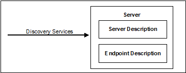
The Discovery Service Set, illustrated in Figure 1, defines Services that allow a Client to discover the Endpoints implemented by a Server and to read the security configuration for each of those Endpoints.
Figure 1 – Discovery Service Set
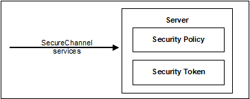
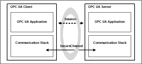
The SecureChannel Service Set, illustrated in Figure 2, defines Services that allow a Client to establish a communication channel to ensure the Confidentiality and Integrity of Messages exchanged with the Server.
Figure 2 – SecureChannel Service Set
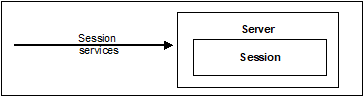
The Session Service Set, illustrated in Figure 3, defines Services that allow the Client to authenticate the user on whose behalf it is acting and to manage Sessions.
Figure 3 – Session Service Set
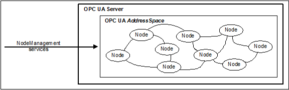
The NodeManagement Service Set, illustrated in Figure 4, defines Services that allow the Client to add, modify and delete Nodes in the AddressSpace.
Figure 4 – NodeManagement Service Set
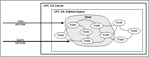
The View Service Set, illustrated in Figure 5, defines Services that allow Clients to browse through the AddressSpace or subsets of the AddressSpace called Views. The Query Service Set allows Clients to get a subset of data from the AddressSpace or the View.
Figure 5 – View Service Set
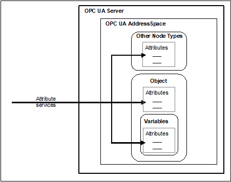
The Attribute Service Set is illustrated in Figure 6. It defines Services that allow Clients to read and write Attributes of Nodes, including their historical values. Since the value of a Variable is modelled as an Attribute, these Services allow Clients to read and write the values of Variables.
Figure 6 – Attribute Service Set
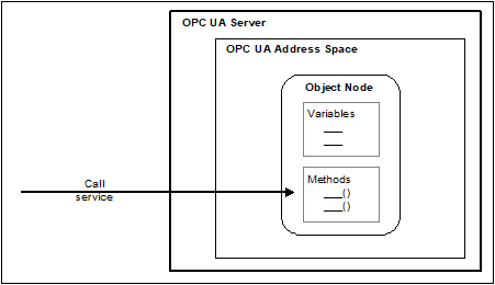
The Method Service Set is illustrated in Figure 7. It defines Services that allow Clients to call methods. Methods run to completion when called. They may be called with method-specific input parameters and may return method-specific output parameters.
Figure 7 – Method Service Set
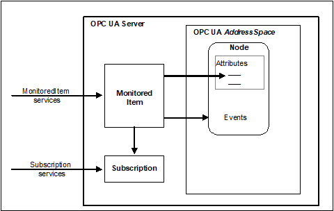
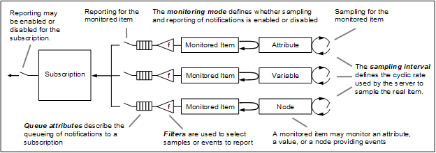
The MonitoredItem Service Set and the Subscription Service Set, illustrated in Figure 8, are used together to subscribe to Nodes in the OPC UA AddressSpace.
The MonitoredItem Service Set defines Services that allow Clients to create, modify, and delete MonitoredItems used to monitor Attributes for value changes and Objects for Events.
These Notifications are queued for transfer to the Client by Subscriptions.
The Subscription Service Set defines Services that allow Clients to create, modify and delete Subscriptions. Subscriptions send Notifications generated by MonitoredItems to the Client. Subscription Services also provide for Client recovery from missed Messages and communication failures.
Figure 8 – MonitoredItem and Subscription Service Sets
Request/response Service procedures describe the processing of requests received by the Server, and the subsequent return of responses. The procedures begin with the requesting Client submitting a Service request Message to the Server.
Upon receipt of the request, the Server processes the Message in two steps. In the first step, it attempts to decode and locate the Service to execute. The error handling for this step is specific to the communication technology used and is described in OPC 10000-6.
If it succeeds, then it attempts to access each operation identified in the request and perform the requested operation. For each operation in the request, it generates a separate success/failure code that it includes in a positive response Message along with any data that is to be returned.
To perform these operations, both the Client and the Server may make use of the API of a Communication Stack to construct and interpret Messages and to access the requested operation.
The implementation of each service request or response handling shall check that each service parameter lies within the specified range for that parameter.
This clause defines the OPC UA Service Sets and their Services. Clause 7 contains the definitions of common parameters used by these Services. Subclause 6.5 describes auditing requirements for all services.
Whether or not a Server supports a Service Set, or a Service within a Service Set, is defined by its Profile. Profiles are described in OPC 10000-7.
Each Service request has a RequestHeader and each Service response has a ResponseHeader.
The RequestHeader structure is defined in 7.33 and contains common request parameters such as authenticationToken, timestamp and requestHandle.
The ResponseHeader structure is defined in 7.34 and contains common response parameters such as serviceResult and diagnosticInfo.
Service results are returned at two levels in OPC UA responses, one that indicates the status of the Service call, and the other that indicates the status of each operation requested by the Service.
Service results are defined via the StatusCode (see 7.39).
The status of the Service call is
represented by the serviceResult contained in the ResponseHeader
(see 7.34). The mechanism for
returning this parameter is specific to the communication technology used to
convey the Service response and is defined in
OPC 10000-6.
The status of individual operations in a request is represented by individual StatusCodes.
The following cases define the use of these parameters.
a) A bad code is returned in serviceResult if the Service itself failed. In this case, a ServiceFault shall be returned instead of the Service response message. The ServiceFault is defined in 7.35.
b) The good code is returned in serviceResult if the Service fully or partially succeeded. In this case, other response parameters are returned. The Client shall always check the response parameters, especially all StatusCodes associated with each operation. These StatusCodes may indicate bad or uncertain results for one or more operations requested in the Service call.
All Services with arrays of operations in the request shall return a bad code in the serviceResult if the array is empty.
The Services define various specific StatusCodes and a Server shall use these specific StatusCodes as described in the Service. A Client should be able to handle these Service specific StatusCodes. In addition, a Client shall expect other common StatusCodes defined in Table 182 and Table 183. Additional details for Client handling of specific StatusCodes may be defined in OPC 10000-7.
If the Server discovers, through some out-of-band mechanism that the application or user credentials used to create a Session or SecureChannel have been compromised, then the Server should immediately terminate all sessions and channels that use those credentials. In this case, the Service result code should be either Bad_IdentityTokenRejected or Bad_CertificateUntrusted.
Message parsing can fail due to syntax errors or if data contained within the message exceeds ranges supported by the receiver. When this happens messages shall be rejected by the receiver. If the receiver is a Server then it shall return a ServiceFault with result code of Bad_DecodingError or Bad_EncodingLimitsExceeded. If the receiver is the Client then the Communication Stack should report these errors to the Client application.
Many applications will place limits on the size of messages and/or data elements contained within these messages. For example, a Server may reject requests containing string values longer than a certain length. These limits are typically set by administrators and apply to all connections between a Client and a Server.
Clients that receive Bad_EncodingLimitsExceeded faults from the Server will likely need to reformulate their requests. The administrator may need to increase the limits for the Client if it receives a response from the Server with this fault.
In some cases, parsing errors are fatal and it is not possible to return a fault. For example, the incoming message could exceed the buffer capacity of the receiver. In these cases, these errors may be treated as a communication fault which requires the SecureChannel to be re-established (see 5.6).
The Client and Server reduce the chances of a fatal error by exchanging their message size limits in the CreateSession service. This will allow either party to avoid sending a message that causes a communication fault. The Server should return a Bad_ResponseTooLarge fault if a serialized response message exceeds the message size specified by the Client. Similarly, the Client Communication Stack should report a Bad_RequestTooLarge error to the application before sending a message that exceeds the Server’s limit.
Note that the message size limits only apply to the raw message body and do not include headers or the effect of applying any security. This means that a message body that is smaller than the specified maximum could still cause a fatal error.
A number of Services expect an array of LocaleIds which are used by a Server to determine in what language or languages LocalizedText should be returned.
The array of LocaleIds is in the preferred order the Client would like the Server to use when selecting the locale of the LocalizedText to be returned. The first LocaleId in the list is the most preferred. If the Server returns a LocalizedText to the Client, the Server shall return the translation which is the most preferred that it can. If it does not have a translation for any of the locales identified in this list, then it shall return LocalizedText in an available locale. See OPC 10000-3 for more details on LocaleIds. If the Client fails to specify at least one LocaleId, the Server shall return any one that it has.
Multi-language LocalizedText can be requested using the special ‘mul’ or ‘qst’ locales as the first entry of the list. See OPC 10000-3 for detail of the special locales and how LocalizedText is used with them. If there are no further entries, the Server shall return all languages available. If there are more languages included after ‘mul’ or ‘qst’, the Server shall return only those languages from that list. If the Server doesn’t have a translation for any of the locales included in the list, then it shall return LocalizeText in an available locale. The special ‘mul’ or ‘qst’ locales shall not be used in Write.
If a Client requests ‘mul’ it shall be prepared to receive a ‘mul’ or another locale, but not ‘qst’ depending on what the Server can provide for a particular LocalizedText.
If a Client requests ‘qst’ it shall be prepared to receive a ‘qst’, ‘mul’ or another locale depending on what the Server can provide for a particular LocalizedText.
This Service Set defines Services used to discover the Endpoints implemented by a Server and to read the security configuration for those Endpoints. The Discovery Services are implemented by individual Servers and by dedicated Discovery Servers. OPC 10000-12 describes how to use the Discovery Services with dedicated Discovery Servers.
Every Server shall have a DiscoveryEndpoint that Clients can access without establishing a Session. This Endpoint may or may not be the same Session Endpoint that Clients use to establish a SecureChannel. Clients read the security information necessary to establish a SecureChannel by calling the GetEndpoints Service on the DiscoveryEndpoint.
In addition, Servers may register themselves with a well-known Discovery Server using the RegisterServer Service. Clients can later discover any registered Servers by calling the FindServers Service on the Discovery Server.
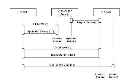
The discovery process using FindServers is illustrated in Figure 9. The establishment of a SecureChannel (with MessageSecurityMode NONE) for FindServers and GetEndpoints is omitted from the figure for clarity.
Figure 9 – Discovery process
The URL for a DiscoveryEndpoint shall provide all of the information that the Client needs to connect to the DiscoveryEndpoint.
Once a Client retrieves the Endpoints, the Client can save this information and use it to connect directly to the Server again without going through the discovery process. If the Client finds that it cannot connect then the Server configuration may have changed and the Client needs to go through the discovery process again.
DiscoveryEndpoints shall not require any message security, but it may require transport layer security. In production systems, Administrators may disable discovery for security reasons and Clients shall rely on cached EndpointDescriptions. To provide support for systems with disabled Discovery Services Clients shall allow Administrators to manually update the EndpointDescriptions used to connect to a Server. Servers shall allow Administrators to disable the DiscoveryEndpoint. If GetEndpoints is disabled and the Server Certificate is updated either automatically with Certificate Manager or manually, Clients will no longer be able to connect to the Server without manual re-configuration of the Client.
A Client shall be careful when using the information returned from a DiscoveryEndpoint since it has no security. A Client does this by comparing the information returned from the DiscoveryEndpoint to the information returned in the CreateSession response. A Client shall verify that:
a) The ApplicationUri specified in the Server Certificate is the same as the ApplicationUri provided in the EndpointDescription.
b) The Server Certificate returned in CreateSession response is the same as the Certificate used to create the SecureChannel.
c) The EndpointDescriptions returned from the DiscoveryEndpoint are the same as the EndpointDescriptions returned in the CreateSession response, but they may be in a different order. For the content, the fields ApplicationUri, EndpointUrl, SecurityMode, SecurityPolicyUri, UserIdentityTokens, TransportProfileUri and SecurityLevel shall be compared for exact match. All other fields are ignored for the comparison.
If the Client detects that one of the above requirements is not fulfilled, then the Client shall close the SecureChannel and report an error.
A Client shall verify the HostName specified in the Server Certificate is the same as the HostName contained in the endpointUrl provided in the EndpointDescription returned by CreateSession. If there is a difference then the Client shall report the difference and may close the SecureChannel. Servers shall add all possible HostNames like MyHost and MyHost.local into the Server Certificate. This includes IP addresses of the host or the HostName exposed by a NAT router used to connect to the Server.
This Service returns the Servers known to a Server or Discovery Server. The behaviour of Discovery Servers is described in detail in OPC 10000-12.
The Client may reduce the number of results returned by specifying filter criteria. A Discovery Server returns an empty list if no Servers match the criteria specified by the Client. The filter criteria supported by this Service are described in 5.5.2.2.
Every Server shall provide a DiscoveryEndpoint that supports this Service. The Server shall always return a record that describes itself, however in some cases more than one record may be returned. Gateway Servers shall return a record for each Server that they provide access to plus (optionally) a record that allows the Gateway Server to be accessed as an ordinary OPC UA Server. Non-transparent redundant Servers shall provide a record for each Server in the RedundantServerSet.
Every Server shall have a globally unique identifier called the ServerUri. This identifier should be a fully qualified domain name; however, it may be a GUID or similar construct that ensures global uniqueness. The ServerUri returned by this Service shall be the same value that appears in index 0 of the ServerArray property (see OPC 10000-5). The ServerUri is returned as the applicationUri field in the ApplicationDescription (see 7.2).
Every Server shall also have a human readable identifier called the ServerName which is not necessarily globally unique. This identifier may be available in multiple locales.
A Server may have multiple HostNames. For this reason, the Client shall pass the URL it used to connect to the Endpoint to this Service. The implementation of this Service shall use this information to return responses that are accessible to the Client via the provided URL.
This Service shall not require message security but it may require transport layer security.
Some Servers may be accessed via a Gateway Server and shall have a value specified for gatewayServerUri in their ApplicationDescription (see 7.2). The discoveryUrls provided in ApplicationDescription shall belong to the Gateway Server. Some Discovery Servers may return multiple records for the same Server if that Server can be accessed via multiple paths.
Table 3 defines the parameters for the Service.
Table 3 – FindServers Service Parameters
|
Name |
Type |
Description |
|
Request |
|
|
|
requestHeader |
RequestHeader |
Common request parameters. The authenticationToken is always null. The authenticationToken shall be ignored if it is provided. The type RequestHeader is defined in 7.33. |
|
endpointUrl |
String |
The network address that the Client used to access the DiscoveryEndpoint. The Server uses this information for diagnostics and to determine what URLs to return in the response. The Server should return a suitable default URL if it does not recognize the HostName in the URL. |
|
localeIds [] |
LocaleId |
List of locales to use. The Server should return the applicationName in the ApplicationDescription defined in 7.2 using one of the locales specified. See locale negotiation in 5.4 which applies to this Service. |
|
serverUris [] |
String |
List of Servers to return. All known Servers are returned if the list is empty. A serverUri matches the applicationUri from the ApplicationDescription defined in 7.2. |
|
|
|
|
|
Response |
|
|
|
responseHeader |
ResponseHeader |
Common response parameters. The ResponseHeader type is defined in 7.34. |
|
servers [] |
ApplicationDescription |
List of Servers that meet criteria specified in the request. This list is empty if no Servers meet the criteria. The ApplicationDescription type is defined in 7.2. |
Common StatusCodes are defined in Table 182.
This Service returns the Servers known to a Discovery Server. Unlike FindServers, this Service is only implemented by Discovery Servers.
The Client may reduce the number of results returned by specifying filter criteria. An empty list is returned if no Server matches the criteria specified by the Client.
This Service shall not require message security but it may require transport layer security.
Each time the Discovery Server creates or updates a record in its cache it shall assign a monotonically increasing identifier to the record. This allows Clients to request records in batches by specifying the identifier for the last record received in the last call to FindServersOnNetwork. To support this the Discovery Server shall return records in numerical order starting from the lowest record identifier. The Discovery Server shall also return the last time the counter was reset for example due to a restart of the Discovery Server. If a Client detects that this time is more recent than the last time the Client called the Service it shall call the Service again with a startingRecordId of 0.
This Service can be used without security and it is therefore vulnerable to denial of service (DOS) attacks. A Server should minimize the amount of processing required to send the response for this Service. This can be achieved by preparing the result in advance.
Table 4 defines the parameters for the Service.
Table 4 – FindServersOnNetwork Service Parameters
|
Name |
Type |
Description |
|
Request |
|
|
|
requestHeader |
RequestHeader |
Common request parameters. The authenticationToken is always null. The authenticationToken shall be ignored if it is provided. The type RequestHeader is defined in 7.33. |
|
startingRecordId |
Counter |
Only records with an identifier greater than this number will be returned. Specify 0 to start with the first record in the cache. |
|
maxRecordsToReturn |
UInt32 |
The maximum number of records to return in the response. 0 indicates that there is no limit. |
|
serverCapabilityFilter[] |
String |
List of Server capability filters. The set of allowed Server capabilities are defined in OPC 10000-12. Only records with all of the specified Server capabilities are returned. The comparison is case insensitive. If this list is empty then no filtering is performed. |
|
|
|
|
|
Response |
|
|
|
responseHeader |
ResponseHeader |
Common response parameters. The ResponseHeader type is defined in 7.34. |
|
lastCounterResetTime |
UtcTime |
The last time the counters were reset. |
|
servers[] |
ServerOnNetwork |
List of DNS service records that meet criteria specified in the request. This list is empty if no Servers meet the criteria. |
|
recordId |
UInt32 |
A unique identifier for the record. This can be used to fetch the next batch of Servers in a subsequent call to FindServersOnNetwork. |
|
serverName |
String |
The name of the Server specified in the mDNS announcement (see OPC 10000-12). This may be the same as the ApplicationName for the Server. |
|
discoveryUrl |
String |
The URL of the DiscoveryEndpoint. |
|
serverCapabilities |
String[] |
The set of Server capabilities supported by the Server. The set of allowed Server capabilities are defined in OPC 10000-12. |
Common StatusCodes are defined in Table 182.
This Service returns the Endpoints supported by a Server and all of the configuration information required to establish a SecureChannel and a Session.
This Service shall not require message security but it may require transport layer security.
A Client may reduce the number of results returned by specifying filter criteria based on LocaleIds and Transport Profile URIs. The Server returns an empty list if no Endpoints match the criteria specified by the Client. The filter criteria supported by this Service are described in 5.5.4.2.
A Server may support multiple security configurations for the same Endpoint. In this situation, the Server shall return separate EndpointDescription records for each available configuration. Clients should treat each of these configurations as distinct Endpoints even if the physical URL happens to be the same.
The security configuration for an Endpoint has four components:
Server Application Instance Certificate
Message Security Mode
Security Policy
Supported User Identity Tokens
The ApplicationInstanceCertificate is used to secure the OpenSecureChannel request (see 5.6.2). The MessageSecurityMode and the SecurityPolicy tell the Client how to secure messages sent via the SecureChannel. The UserIdentityTokens tell the Client which type of user credentials shall be passed to the Server in the ActivateSession request (see 5.7.3).
If the securityPolicyUri is None and none of the UserTokenPolicies requires encryption, the Client shall ignore the ApplicationInstanceCertificate. If the securityPolicyUri is not None or one of the UserTokenPolicies requires encryption, the Server shall include the ApplicationInstanceCertificate in the EndpointDescription.
Each EndpointDescription also specifies a URI for the Transport Profile that the Endpoint supports. The Transport Profiles specify information such as message encoding format and protocol version and are defined in OPC 10000-7.
Messages are secured by applying standard cryptography algorithms to the messages before they are sent over the network. The exact set of algorithms used depends on the SecurityPolicy for the Endpoint. OPC 10000-7 defines Profiles for common SecurityPolicies and assigns a unique URI to them. It is expected that applications have built in knowledge of the SecurityPolicies that they support, as a result, only the Profile URI for the SecurityPolicy is specified in the EndpointDescription. A Client cannot connect to an Endpoint that does not support a SecurityPolicy that it recognizes.
An EndpointDescription may specify that the message security mode is NONE. This configuration is not recommended unless the applications are communicating on a physically isolated network where the risk of intrusion is extremely small. If the message security is NONE then it is possible for Clients to deliberately or accidentally hijack Sessions created by other Clients.
A Server may have multiple HostNames. For this reason, the Client shall pass the URL it used to connect to the Endpoint to this Service. The implementation of this Service shall use this information to return responses that are accessible to the Client via the provided URL.
This Service can be used without security and it is therefore vulnerable to Denial of Service (DOS) attacks. A Server should minimize the amount of processing required to send the response for this Service. This can be achieved by preparing the result in advance. The Server should also add a short delay before starting processing of a request during high traffic conditions.
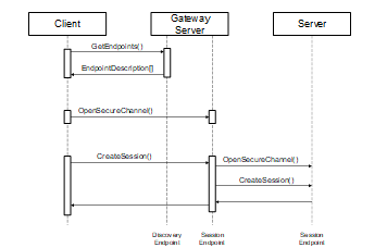
Some of the EndpointDescriptions returned in a response shall specify the Endpoint information for a Gateway Server that can be used to access another Server. In these situations, the gatewayServerUri is specified in the EndpointDescription and all security checks used to verify Certificates shall use the gatewayServerUri (see 6.1.3) instead of the serverUri.
To connect to a Server via the gateway the Client shall first establish a SecureChannel with the Gateway Server. Then the Client shall call the CreateSession service and pass the serverUri specified in the EndpointDescription to the Gateway Server. The Gateway Server shall then connect to the underlying Server on behalf of the Client. The process of connecting to a Server via a Gateway Server is illustrated in Figure 10.
Figure 10 – Using a Gateway Server
Table 5 defines the parameters for the Service.
Table 5 – GetEndpoints Service Parameters
|
Name |
Type |
Description |
|
Request |
|
|
|
requestHeader |
RequestHeader |
Common request parameters. The authenticationToken is always null. The authenticationToken shall be ignored if it is provided. The type RequestHeader is defined in 7.33. |
|
endpointUrl |
String |
The network address that the Client used to access the DiscoveryEndpoint. The Server uses this information for diagnostics and to determine what URLs to return in the response. The Server should return a suitable default URL if it does not recognize the HostName in the URL. |
|
localeIds [] |
LocaleId |
List of locales to use. See locale negotiation in 5.4 which applies to this Service. |
|
profileUris [] |
String |
List of Transport Profile that the returned Endpoints shall support. OPC 10000-7 defines URIs for the Transport Profiles. All Endpoints are returned if the list is empty. If the URI is a URL, this URL may have a query string appended. The Transport Profiles that support query strings are defined in OPC 10000-7. |
|
|
|
|
|
Response |
|
|
|
responseHeader |
ResponseHeader |
Common response parameters. The ResponseHeader type is defined in 7.34. |
|
Endpoints [] |
EndpointDescription |
List of Endpoints that meet criteria specified in the request. This list is empty if no Endpoints meet the criteria. The EndpointDescription type is defined in 7.14. |
Common StatusCodes are defined in Table 182.
This Service is implemented by Discovery Servers.
This Service registers a Server with a Discovery Server. This Service will be called by a Server or a separate configuration utility. Clients will not use this Service.
A Server shall establish a SecureChannel with the Discovery Server before calling this Service. The SecureChannel is described in 5.6. The Administrator of the Server shall provide the Server with an EndpointDescription for the Discovery Server as part of the configuration process. Discovery Servers shall reject registrations if the serverUri provided does not match the applicationUri in Server Certificate used to create the SecureChannel.
This Service can only be invoked via SecureChannels that support Client authentication (i.e. HTTPS cannot be used to call this Service).
A Server only provides its serverUri and the URLs of the DiscoveryEndpoints to the Discovery Server. Clients shall use the GetEndpoints Service to fetch the most up to date configuration information directly from the Server.
The Server shall provide a localized name for itself in all locales that it supports.
Servers shall be able to register themselves with a Discovery Server running on the same machine. The exact mechanisms depend on the Discovery Server implementation and are described in OPC 10000-6.
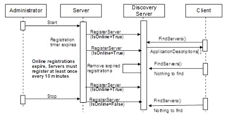
There are two types of Server applications: those which are manually launched including a start by the operating system at boot and those that are automatically launched when a Client attempts to connect. The registration process that a Server shall use depends on which category it falls into.
The registration process for manually launched Servers is illustrated in Figure 11.
Figure 11 – The Registration Process – Manually Launched Servers
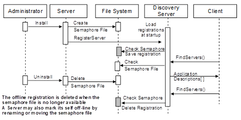
The registration process for automatically launched Servers is illustrated in Figure 12.
Figure 12 – The Registration Process – Automatically Launched Servers
The registration process is designed to be platform independent, robust and able to minimize problems created by configuration errors. For that reason, Servers shall register themselves more than once.
Under normal conditions, manually launched Servers shall periodically register with the Discovery Server as long as they are able to receive connections from Clients. If a Server goes offline then it shall register itself once more and indicate that it is going offline. The period of the recurring registration should be configurable; however, the maximum is 10 minutes. If an error occurs during registration (e.g. the Discovery Server is not running) then the Server shall periodically re-attempt registration. The frequency of these attempts should start at 1 second but gradually increase until the registration frequency is the same as what it would be if no errors occurred. The recommended approach would be to double the period of each attempt until reaching the maximum.
When an automatically launched Server (or its install program) registers with the Discovery Server it shall provide a path to a semaphore file which the Discovery Server can use to determine if the Server has been uninstalled from the machine. The Discovery Server shall have read access to the file system that contains the file.
Table 6 defines the parameters for the Service.
Table 6 – RegisterServer Service Parameters
|
Name |
Type |
Description |
|
Request |
|
|
|
requestHeader |
RequestHeader |
Common request parameters. The authenticationToken is always null. The type RequestHeader is defined in 7.33. |
|
Server |
RegisteredServer |
The Server to register. The type RegisteredServer is defined in 7.32. |
|
|
|
|
|
Response |
|
|
|
ResponseHeader |
ResponseHeader |
Common response parameters. The type ResponseHeader is defined in 7.34. |
Table 7 defines the Service results specific to this Service. Common StatusCodes are defined in Table 182.
Table 7 – RegisterServer Service Result Codes
|
Symbolic Id |
Description |
|
Bad_InvalidArgument |
See Table 182 for the description of this result code. |
|
Bad_ServerUriInvalid |
See Table 182 for the description of this result code. |
|
Bad_ServerNameMissing |
No ServerName was specified. |
|
Bad_DiscoveryUrlMissing |
No discovery URL was specified. |
|
Bad_SemaphoreFileMissing |
The semaphore file specified is not valid. |
This Service is implemented by Discovery Servers.
This Service allows a Server to register its DiscoveryUrls and capabilities with a Discovery Server. It extends the registration information from RegisterServer with information necessary for FindServersOnNetwork. This Service will be called by a Server or a separate configuration utility. Clients will not use this Service.
Servers that support RegisterServer2 shall try to register with the Discovery Server using this Service and shall fall back to RegisterServer if RegisterServer2 fails with the status Bad_ServiceUnsupported.
A Discovery Server that implements this Service needs to assign unique record ids each time this Service is called. See 5.5.3 for more details.
This Service can only be invoked via SecureChannels that support Client authentication (i.e. HTTPS cannot be used to call this Service).
Table 8 defines the parameters for the Service.
Table 8 – RegisterServer2
|
Name |
Type |
Description |
|
Request |
|
|
|
requestHeader |
RequestHeader |
Common request parameters. The authenticationToken is always null. The type RequestHeader is defined in 7.33. |
|
Server |
RegisteredServer |
The Server to register. The type RegisteredServer is defined in 7.32. |
|
discoveryConfiguration [] |
ExtensibleParameter DiscoveryConfiguration |
Additional configuration settings for the Server to register. The discoveryConfiguration is an extensible parameter type defined in 7.13. Discovery Servers that do not understand a configuration shall return Bad_NotSupported for this configuration. |
|
|
|
|
|
Response |
|
|
|
responseHeader |
ResponseHeader |
Common response parameters. The type ResponseHeader is defined in 7.34. |
|
configurationResults [] |
StatusCode |
List of results for the discoveryConfiguration parameters. |
|
diagnosticInfos [] |
DiagnosticInfo |
List of diagnostic information for the discoveryConfiguration parameters. This list is empty if diagnostics information was not requested in the request header or if no diagnostic information was encountered in processing of the request. |
Table 9 defines the Service results specific to this Service. Common StatusCodes are defined in Table 182.
Table 9 – RegisterServer2 Service Result Codes
|
Symbolic Id |
Description |
|
Bad_InvalidArgument |
See Table 182 for the description of this result code. |
|
Bad_ServerUriInvalid |
See Table 182 for the description of this result code. |
|
Bad_ServerNameMissing |
No ServerName was specified. |
|
Bad_DiscoveryUrlMissing |
No discovery URL was specified. |
|
Bad_SemaphoreFileMissing |
The semaphore file specified is not valid. |
|
Bad_ServiceUnsupported |
See Table 182 for the description of this result code. |
Table 10 defines values for the operation level configurationResults parameters that are specific to this Service. Common StatusCodes are defined in Table 183.
Table 10 – RegisterServer2 Operation Level Result Codes
|
Symbolic Id |
Description |
|
Bad_NotSupported |
See Table 183 for the description of this result code. |
This Service Set defines Services used to open a communication channel that ensures the Confidentiality and Integrity of all Messages exchanged with the Server. The base concepts for OPC UA security are defined in OPC 10000-2.
The SecureChannel Services are unlike other Services because they are not implemented directly by the OPC UA Application. Instead, they are provided by the Communication Stack on which the OPC UA Application is built. For example, an OPC UA Server may be built on a stack that allows applications to establish a SecureChannel using HTTPS. In these cases, the OPC UA Application shall verify that the Message it received was in the context of an HTTPS connection. OPC 10000-6 describes how the SecureChannel Services are implemented.
A SecureChannel is a long-running logical connection between a single Client and a single Server. This channel maintains a set of keys known only to the Client and Server, which are used to sign and encrypt Messages sent across the network to ensure Confidentiality and Integrity. The SecureChannel Services allow the Client and Server to securely negotiate the keys to use.
Logical connections may be initiated by the Client or by the Server as described in OPC 10000-6. After the connection is initiated, the SecureChannel is opened and closed by the Client using the SecureChannel Services.
An EndpointDescription tells a Client how to establish a SecureChannel with a given Endpoint. A Client may obtain the EndpointDescription from a Discovery Server, via some non-UA defined directory server or from its own configuration.
The exact algorithms used to sign and encrypt Messages are described in the SecurityPolicy field of the EndpointDescription. A Client shall use these algorithms when it creates a SecureChannel.
It should be noted that some SecurityPolicies defined in OPC 10000-7 will turn off authentication and encryption resulting in a SecureChannel that provides no security.
When a Client and Server are communicating via a SecureChannel, they shall verify that all incoming Messages have been signed and encrypted according to the requirements specified in the EndpointDescription. An OPC UA Application shall not process any Message that does not conform to these requirements.
The relationship between the SecureChannel and the OPC UA Application depends on the implementation technology. OPC 10000-6 defines any requirements that depend on the technology used.
The correlation between the OPC UA Application Session and the SecureChannel is illustrated in Figure 13. The Communication Stack is used by the OPC UA Applications to exchange Messages. In the first step, the SecureChannel Services are used to establish a SecureChannel between the two Communication Stacks which allows the secure exchange of Messages. In the second step, the OPC UA Applications use the Session Service Set to establish an OPC UA Application Session.
Figure 13 – SecureChannel and Session Services
Once a Client has established a Session it may wish to access the Session from a different SecureChannel. The Client can do this by validating the new SecureChannel with the ActivateSession Service described in 5.7.3.
If a Server acts as a Client to other Servers, which is commonly referred to as Server chaining, then the Server shall be able to maintain user level security. By this we mean that the user identity should be passed to the underlying Server or it should be mapped to an appropriate user identity in the underlying Server. It is unacceptable to ignore user level security. This is required to ensure that security is maintained and that a user does not obtain information that they should not have access to. Whenever possible a Server should impersonate the original Client by passing the original Client’s user identity to the underlying Server when it calls the ActivateSession Service. If impersonation is not an option then the Server shall map the original Client’s user identity onto a new user identity which the underlying Server does recognize.
This Service is used to open or renew a SecureChannel that can be used to ensure Confidentiality and Integrity for Message exchange during a Session. This Service requires the Communication Stack to apply the various security algorithms to the Messages as they are sent and received. Specific implementations of this Service for different Communication Stacks are described in OPC 10000-6.
Each SecureChannel has a globally-unique identifier and is valid for a specific combination of Client and Server application instances. Each channel contains one or more SecurityTokens that identify a set of cryptography keys that are used to encrypt and authenticate Messages. SecurityTokens also have globally-unique identifiers which are attached to each Message secured with the token. This allows an authorized receiver to know how to decrypt and verify the Message.
SecurityTokens have a finite lifetime negotiated with this Service. However, differences between the system clocks on different machines and network latencies mean that valid Messages could arrive after the token has expired. To prevent valid Messages from being discarded, the applications should do the following:
a) Clients should request a new SecurityToken after 75 % of its lifetime has elapsed. This should ensure that Clients will receive the new SecurityToken before the old one actually expires.
b) Servers shall use the existing SecurityToken to secure outgoing Messages until the SecurityToken expires or the Server receives a Message secured with a new SecurityToken. This should ensure that Clients do not reject Messages secured with the new SecurityToken that arrive before the Client receives the new SecurityToken.
c) Clients should accept Messages secured by an expired SecurityToken for up to 25 % of the token lifetime. This should ensure that Messages sent by the Server before the token expired are not rejected because of network delays.
Each SecureChannel exists until it is explicitly closed or until the last token has expired and the overlap period has elapsed. A Server application should limit the number of SecureChannels. To protect against misbehaving Clients and denial of service attacks, the Server shall close the oldest unused SecureChannel that has no Session assigned before reaching the maximum number of supported SecureChannels. When Session-less Service invocation is done through a transport mapping that requires the OpenSecureChannel Service, the Server shall maintain a last used time for the SecureChannel to detect the oldest unused SecureChannel.
The OpenSecureChannel request and response Messages shall be signed with the sender's private key. These Messages shall always be encrypted. If the transport layer does not provide encryption, then these Messages shall be encrypted with the receiver's public key. These requirements for OpenSecureChannel only apply if the securityPolicyUri is not None.
If the protocol defined in OPC 10000-6 requires that Application Instance Certificates are used in the OpenSecureChannel Service, then Clients and Servers shall verify that the same Certificates are used in the CreateSession and ActivateSession Services. Certificates are not provided and shall not be verified if the securityPolicyUri is None.
If the securityPolicyUri is not None, a Client shall verify the HostName specified in the Server Certificate is the same as the HostName contained in the endpointUrl. If there is a difference then the Client shall report the difference and may choose to not open the SecureChannel. Servers shall add all possible HostNames like MyHost and MyHost.mycompany.com into the Server Certificate. This includes IP addresses of the host or the HostName exposed by a NAT router used to connect to the Server. Servers shall not append the 'local' top level domain to any domains declared in their Certificate; an unqualified domain name is used if a more appropriate qualifier does not exist. Clients using a URL returned from an LDS-ME shall remove the 'local' top level domain when checking the domain against the Server Certificate.
Clients should be prepared to replace the HostName and port returned in the EndpointDescription with the HostName or the IP addresses and the port they used to call GetEndpoints. The Client shall still execute the HostName verification comparing the HostName used by the Client to create the SecureChannel with the HostName list in the Server Certificate. See Table 106 for more details.
Table 11 defines the parameters for the Service.
Unlike other Services, the parameters for this Service provide only an abstract definition. The concrete representation on the network depends on the mappings defined in OPC 10000-6.
Table 11 – OpenSecureChannel Service Parameters
|
Name |
Type |
Description |
|
Request |
|
|
|
requestHeader |
RequestHeader |
Common request parameters. The authenticationToken is always null. The type RequestHeader is defined in 7.33. |
|
clientCertificate |
ApplicationInstanceCertificate |
A Certificate that identifies the Client. The OpenSecureChannel request shall be signed with the private key for this Certificate. The ApplicationInstanceCertificate type is defined in 7.3. If the securityPolicyUri is None, the Server shall ignore the ApplicationInstanceCertificate. |
|
requestType |
Enum SecurityToken RequestType |
The type of SecurityToken request: An enumeration that shall be one of the following: ISSUE creates a new SecurityToken for a new SecureChannel. RENEW creates a new SecurityToken for an existing SecureChannel. |
|
secureChannelId |
BaseDataType |
The identifier for the SecureChannel that the new token should belong to. This parameter shall be null when creating a new SecureChannel. The concrete security protocol definition in OPC 10000-6 chooses the concrete DataType. |
|
securityMode |
Enum MessageSecurityMode |
The type of security to apply to the messages. The type MessageSecurityMode type is defined in 7.20. A SecureChannel may need to be created even if the securityMode is NONE. The exact behaviour depends on the mapping used and is described in the OPC 10000-6. |
|
securityPolicyUri |
String |
The URI for SecurityPolicy to use when securing messages sent over the SecureChannel. The set of known URIs and the SecurityPolicies associated with them are defined in OPC 10000-7. |
|
clientNonce |
ByteString |
A random number that shall not be used in any other request. A new clientNonce shall be generated for each time a SecureChannel is renewed. This parameter shall have a length equal to the SecureChannelNonceLength defined for the SecurityPolicy in OPC 10000-7. The SecurityPolicy is identified by the securityPolicyUri. |
|
requestedLifetime |
Duration |
The requested lifetime, in milliseconds, for the new SecurityToken. It specifies when the Client expects to renew the SecureChannel by calling the OpenSecureChannel Service again. If a SecureChannel is not renewed, then all Messages sent using the current SecurityTokens shall be rejected by the receiver. Several cryptanalytic attacks become easier as more material encrypted with a specific key is available. By limiting the amount of data processed using a particular key, those attacks are made more difficult. Therefore the volume of data exchanged between Client and Server shall be limited by establishing a new SecurityToken after the lifetime. The setting of the requested lifetime depends on the expected number of exchanged messages and their size in the lifetime. A higher volume of data requires shorter lifetime. |
|
|
|
|
|
Response |
|
|
|
responseHeader |
ResponseHeader |
Common response parameters (see 7.34 for ResponseHeader type definition). |
|
securityToken |
ChannelSecurityToken |
Describes the new SecurityToken issued by the Server. This structure is defined in-line with the following indented items. |
|
channelId |
BaseDataType |
A unique identifier for the SecureChannel. This is the identifier that shall be supplied whenever the SecureChannel is renewed. The concrete security protocol definition in OPC 10000-6 chooses the concrete DataType. |
|
tokenId |
ByteString |
A unique identifier for a single SecurityToken within the channel. This is the identifier that shall be passed with each Message secured with the SecurityToken. |
|
createdAt |
UtcTime |
The time when the SecurityToken was created. |
|
revisedLifetime |
Duration |
The lifetime of the SecurityToken in milliseconds. The UTC expiration time for the token may be calculated by adding the lifetime to the createdAt time. The revised lifetime shall be used by the Client to renew a SecureChannel before it expires even if the MessageSecurityMode is NONE. |
|
serverNonce |
ByteString |
A random number that shall not be used in any other request. A new serverNonce shall be generated for each time a SecureChannel is renewed. This parameter shall have a length equal to the SecureChannelNonceLength defined for the SecurityPolicy in OPC 10000-7. The SecurityPolicy is identified by the securityPolicyUri. |
Table 12 defines the Service results specific to this Service. Common StatusCodes are defined in Table 182.
Table 12 – OpenSecureChannel Service Result Codes
|
Symbolic Id |
Description |
|
Bad_SecurityChecksFailed |
See Table 182 for the description of this result code. |
|
Bad_CertificateTimeInvalid |
See Table 182 for the description of this result code. |
|
Bad_CertificateIssuerTimeInvalid |
See Table 182 for the description of this result code. |
|
Bad_CertificateHostNameInvalid |
See Table 182 for the description of this result code. |
|
Bad_CertificateUriInvalid |
See Table 182 for the description of this result code. |
|
Bad_CertificateUseNotAllowed |
See Table 182 for the description of this result code. |
|
Bad_CertificateIssuerUseNotAllowed |
See Table 182 for the description of this result code. |
|
Bad_CertificateUntrusted |
See Table 182 for the description of this result code. |
|
Bad_CertificateRevocationUnknown |
See Table 182 for the description of this result code. |
|
Bad_CertificateIssuerRevocationUnknown |
See Table 182 for the description of this result code. |
|
Bad_CertificateRevoked |
See Table 182 for the description of this result code. |
|
Bad_CertificateIssuerRevoked |
See Table 182 for the description of this result code. |
|
Bad_RequestTypeInvalid |
The SecurityToken request type is not valid. |
|
Bad_SecurityModeRejected |
The security mode does not meet the requirements set by the server. |
|
Bad_SecurityPolicyRejected |
The security policy does not meet the requirements set by the Server. |
|
Bad_SecureChannelIdInvalid |
See Table 182 for the description of this result code. |
|
Bad_NonceInvalid |
See Table 182 for the description of this result code. A Server shall check the minimum length of the Client nonce and return this status if the length is below 32 bytes. A check for duplicated nonce can only be done in OpenSecureChannel calls with the request type RENEW. |
This Service is used to terminate a SecureChannel.
The request Messages shall be signed with the appropriate key associated with the current token for the SecureChannel.
Table 13 defines the parameters for the Service.
Specific protocol mappings defined in OPC 10000-6 may choose to omit the response.
Table 13 – CloseSecureChannel Service Parameters
|
Name |
Type |
Description |
|
Request |
|
|
|
requestHeader |
RequestHeader |
Common request parameters. The authenticationToken is always null. The type RequestHeader is defined in 7.33. |
|
secureChannelId |
BaseDataType |
The identifier for the SecureChannel to close. The concrete security protocol definition in OPC 10000-6 chooses the concrete DataType. |
|
|
|
|
|
Response |
|
|
|
responseHeader |
ResponseHeader |
Common response parameters (see 7.34 for ResponseHeader definition). |
Table 14 defines the Service results specific to this Service. Common StatusCodes are defined in Table 182.
Table 14 – CloseSecureChannel Service Result Codes
|
Symbolic Id |
Description |
|
Bad_SecureChannelIdInvalid |
See Table 182 for the description of this result code. |
This Service Set defines Services for an application layer connection establishment in the context of a Session.
This Service is used by an OPC UA Client to create a Session and the Server returns two values which uniquely identify the Session. The first value is the sessionId which is used to identify the Session in the audit logs and in the Server’s AddressSpace. The second is the authenticationToken which is used to associate an incoming request with a Session.
Before calling this Service, the Client shall create a SecureChannel with the OpenSecureChannel Service to ensure the Integrity of all Messages exchanged during a Session. This SecureChannel has a unique identifier which the Server shall associate with the authenticationToken. The Server may accept requests with the authenticationToken only if they are associated with the same SecureChannel that was used to create the Session. The Client may associate a new SecureChannel with the Session by calling ActivateSession. For the N Sessions supported by a Server, the Server shall support N+1 SecureChannels. A Server may support multiple Sessions for one SecureChannel.
The SecureChannel is always managed by the Communication Stack which means it shall provide APIs which the Server can use to find out information about the SecureChannel used for any given request. The Communication Stack shall, at a minimum, provide the SecurityPolicy and SecurityMode used by the SecureChannel. It shall also provide a SecureChannelId which uniquely identifies the SecureChannel or the Client Certificate used to establish the SecureChannel. The Server uses one of these to identify the SecureChannel used to send a request. Clause 7.36 describes how to create the authenticationToken for different types of Communication Stack.
Depending upon on the SecurityPolicy and the SecurityMode of the SecureChannel, the exchange of ApplicationInstanceCertificates and Nonces may be optional and the signatures may be empty. See OPC 10000-7 for the definition of SecurityPolicies and the handling of these parameters.
The Server returns its EndpointDescriptions in the response. Clients use this information to determine whether the list of EndpointDescriptions returned from the DiscoveryEndpoint matches the Endpoints that the Server has. If there is a difference then the Client shall close the Session and report an error. The Server returns all EndpointDescriptions for the serverUri specified by the Client in the request. The Client only verifies EndpointDescriptions with a transportProfileUri that matches the profileUri specified in the original GetEndpoints request. A Client may skip this check if the EndpointDescriptions were provided by a trusted source such as the Administrator.
The Session created with this Service shall not be used until the Client calls the ActivateSession Service and proves possession of its Application Instance Certificate and any user identity token that it provided.
A Server application should limit the number of Sessions. To protect against misbehaving Clients and denial of service attacks, the Server shall close the oldest Session that is not activated before reaching the maximum number of supported Sessions.
The SoftwareCertificates parameter in the Server response is deprecated to reduce the message size for OPC UA Applications with limited resources. The SoftwareCertificates are provided in the Server’s AddressSpace as defined in OPC 10000-5. A SoftwareCertificate identifies the capabilities of the Server and also contains the list of OPC UA Profiles supported by the Server. OPC UA Profiles are defined in OPC 10000-7.
Additional Certificates issued by other organizations may be included to identify additional Server capabilities. Examples of these Profiles include support for specific information models and support for access to specific types of devices.
When a Session is created, the Server adds an entry for the Client in its SessionDiagnosticsArray Variable. See OPC 10000-5 for a description of this Variable.
Sessions are created to be independent of the underlying communications connection. Therefore, if a communications connection fails, the Session is not immediately affected. When the communication connection fails, the Client should try to create a new communication connection and call ActivateSession again. See 6.7 for more details.
Sessions are terminated by the Server automatically if the Client fails to issue a Service request on the Session within the timeout period negotiated by the Server in the CreateSession Service response. This protects the Server against Client failures and against situations where a failed underlying connection cannot be re-established. Clients shall be prepared to submit requests in a timely manner to prevent the Session from closing automatically. Clients may explicitly terminate Sessions using the CloseSession Service.
When a Session is terminated, all outstanding requests on the Session are aborted and Bad_SessionClosed StatusCodes are returned to the Client. In addition, the Server deletes the entry for the Client from its SessionDiagnosticsArray Variable and notifies any other Clients who were subscribed to this entry.
If a Client invokes the CloseSession Service then all Subscriptions associated with the Session are also deleted if the deleteSubscriptions flag is set to TRUE. If a Server terminates a Session for any other reason, Subscriptions associated with the Session, are not deleted. Each Subscription has its own lifetime to protect against data loss in the case of a Session termination. In these cases, the Subscription can be reassigned to another Client before its lifetime expires.
Some Servers, such as aggregating Servers, also act as Clients to other Servers. These Servers typically support more than one system user, acting as their agent to the Servers that they represent. Security for these Servers is supported at two levels.
First, each OPC UA Service request contains a string parameter that is used to carry an audit record id. A Client, or any Server operating as a Client, such as an aggregating Server, can create a local audit log entry for a request that it submits. This parameter allows the Client to pass the identifier for this entry with the request. If the Server also maintains an audit log, then it can include this id in the audit log entry that it writes. When the log is examined and the entry is found, the examiner will be able to relate it directly to the audit log entry created by the Client. This capability allows for traceability across audit logs within a system. See OPC 10000-2 for additional information on auditing. A Server that maintains an audit log shall provide the information in the audit log entries via event Messages defined in this document. The Server may choose to only provide the Audit information via event Messages. The Audit EventType is defined in OPC 10000-3.
Second, these aggregating Servers may open independent Sessions to the underlying Servers for each Client that accesses data from them. Figure 14 illustrates this concept.
Figure 14 – Multiplexing users on a Session
Table 15 defines the parameters for the Service.
Table 15 – CreateSession Service Parameters
|
Name |
Type |
Description |
|
Request |
|
|
|
requestHeader |
RequestHeader |
Common request parameters. The authenticationToken is always null. The type RequestHeader is defined in 7.33. |
|
clientDescription |
Application Description |
Information that describes the Client application. The type ApplicationDescription is defined in 7.2. |
|
serverUri |
String |
This value is only specified if the EndpointDescription has a gatewayServerUri. This value is the applicationUri from the EndpointDescription which is the applicationUri for the underlying Server. The type EndpointDescription is defined in 7.14. |
|
endpointUrl |
String |
The network address that the Client used to access the Session Endpoint. The Server uses this information for diagnostics and to determine what URLs to return in the response. The Server should return a suitable default URL if it does not recognize the HostName in the URL |
|
sessionName |
String |
Human readable string that identifies the Session. The Server makes this name and the sessionId visible in its AddressSpace for diagnostic purposes. The Client should provide a name that is unique for the instance of the Client. If this parameter is null or empty the Server shall assign a value. |
|
clientNonce |
ByteString |
A random number that should never be used in any other request. This number shall have a length between 32 and 128 bytes inclusive. The Server shall check the length. The Server shall use this value to prove possession of its Application Instance Certificate in the response. |
|
clientCertificate |
ApplicationInstance Certificate |
The Application Instance Certificate issued to the Client. The ApplicationInstanceCertificate type is defined in 7.3. If the securityPolicyUri is None, the Server shall ignore the ApplicationInstanceCertificate. If the SecurityMode is not None, a Client shall prove possession by using the private key to create a Signature using the Nonce provided by the Server in the response. If the SecurityMode is not None, the Server shall verify that this Application Instance Certificate is the same as the one it used to create the SecureChannel. |
|
Requested SessionTimeout |
Duration |
Requested maximum number of milliseconds that a Session should remain open without activity. If the Client fails to issue a Service request within this interval, then the Server shall automatically terminate the Client Session. |
|
maxResponse MessageSize |
UInt32 |
The maximum size, in bytes, for the body of any response message. The Server should return a Bad_ResponseTooLarge service fault if a response message exceeds this limit. The value zero indicates that this parameter is not used. The transport protocols defined in OPC 10000-6 may imply minimum message sizes. More information on the use of this parameter is provided in 5.3. |
|
Response |
|
|
|
responseHeader |
ResponseHeader |
Common response parameters (see 7.34 for ResponseHeader type). |
|
sessionId |
NodeId |
A unique NodeId assigned by the Server to the Session. This identifier is used to access the diagnostics information for the Session in the Server AddressSpace. It is also used in the audit logs and any events that report information related to the Session. The Session diagnostic information is described in OPC 10000-5. Audit logs and their related events are described in 6.5. |
|
authentication Token |
Session AuthenticationToken |
A unique identifier assigned by the Server to the Session. This identifier shall be passed in the RequestHeader of each request and is used with the SecureChannelId to determine whether a Client has access to the Session. This identifier shall not be reused in a way that the Client or the Server has a chance of confusing them with a previous or existing Session. The SessionAuthenticationToken type is described in 7.36. |
|
revisedSession Timeout |
Duration |
Actual maximum number of milliseconds that a Session shall remain open without activity. The Server should attempt to honour the Client request for this parameter, but may negotiate this value up or down to meet its own constraints. |
|
serverNonce |
ByteString |
A random number that should never be used in any other request. This number shall have a length between 32 and 128 bytes inclusive . The Client shall check the length. The Client shall use this value to prove possession of its Application Instance Certificate in the ActivateSession request. This value may also be used to prove possession of the userIdentityToken it specified in the ActivateSession request. |
|
serverCertificate |
ApplicationInstance Certificate |
The Application Instance Certificate issued to the Server. A Server shall prove possession by using the private key to sign the Nonce provided by the Client in the request. For SecureChannels that use the Application Instance Certificate the Client shall verify that this Certificate is the same as the one it used to create the SecureChannel. The ApplicationInstanceCertificate type is defined in 7.3. If the securityPolicyUri is None and none of the UserTokenPolicies requires encryption, the Client shall ignore the ApplicationInstanceCertificate. |
|
serverEndpoints [] |
EndpointDescription |
List of Endpoints that the Server supports. The Server shall return a set of EndpointDescriptions available for the serverUri specified in the request. All Endpoints are returned if the serverUri is null or empty. The EndpointDescription type is defined in 7.14. If the Client used a DiscoveryEndpoint to select the security options from the available EndpointDescriptions, the Client shall verify this list with the list from a DiscoveryEndpoint. If the Client has the security options configured for the connection to the Server, it uses this configuration and ignores the list. A Client shall compare only the EndpointDescriptions that match the transportProfileUri of the current SecureChannel. It is recommended that Servers only include the server.applicationUri, endpointUrl, securityMode, securityPolicyUri, userIdentityTokens, transportProfileUri and securityLevel with all other parameters set to null or empty. Only the recommended parameters shall be verified by the Client. |
|
serverSoftware Certificates [] |
SignedSoftware Certificate |
This parameter is no longer used and the array shall be empty. The SoftwareCertificates are provided in the Server AddressSpace as defined in OPC 10000-5. |
|
serverSignature |
SignatureData |
This is a signature generated with the private key associated with the serverCertificate. This parameter is calculated by appending the clientNonce to the clientCertificate and signing the resulting sequence of bytes. If the clientCertificate contains a chain, the signature calculation shall be done only with the leaf Certificate. For backward compatibility a Client shall check the signature with the full chain if the check with the leaf Certificate fails. The SignatureAlgorithm shall be the AsymmetricSignatureAlgorithm specified in the SecurityPolicy for the Endpoint. The SignatureData type is defined in 7.37. The clientCertificate shall be validated according to the rules in 6.1.3 even if the Server chooses to allow connections from untrusted Clients. This validation may have occurred when the SecureChannel was established and does not need to be repeated. The Signature is not generated if the SecurityMode is None. |
|
maxRequest MessageSize |
UInt32 |
The maximum size, in bytes, for the body of any request message. The Client Communication Stack should return a Bad_RequestTooLarge error to the application if a request message exceeds this limit. The value zero indicates that this parameter is not used. See OPC 10000-6 for protocol specific minimum or default values. 5.3 provides more information on the use of this parameter. |
Table 16 defines the Service results specific to this Service. Common StatusCodes are defined in Table 182.
Table 16 – CreateSession Service Result Codes
|
Symbolic Id |
Description |
|
Bad_SecureChannelIdInvalid |
See Table 182 for the description of this result code. |
|
Bad_NonceInvalid |
See Table 182 for the description of this result code. A Server shall check the length of the Client nonce and return this status if the length is less than 32 bytes or greater than 128 bytes. A check for a duplicated nonce is optional and requires access to the nonce used to create the secure channel. |
|
Bad_SecurityChecksFailed |
See Table 182 for the description of this result code. |
|
Bad_CertificateTimeInvalid |
See Table 182 for the description of this result code. |
|
Bad_CertificateIssuerTimeInvalid |
See Table 182 for the description of this result code. |
|
Bad_CertificateHostNameInvalid |
See Table 182 for the description of this result code. |
|
Bad_CertificateUriInvalid |
See Table 182 for the description of this result code. |
|
Bad_CertificateUseNotAllowed |
See Table 182 for the description of this result code. |
|
Bad_CertificateIssuerUseNotAllowed |
See Table 182 for the description of this result code. |
|
Bad_CertificateUntrusted |
See Table 182 for the description of this result code. |
|
Bad_CertificateRevocationUnknown |
See Table 182 for the description of this result code. |
|
Bad_CertificateIssuerRevocationUnknown |
See Table 182 for the description of this result code. |
|
Bad_CertificateRevoked |
See Table 182 for the description of this result code. |
|
Bad_CertificateIssuerRevoked |
See Table 182 for the description of this result code. |
|
Bad_TooManySessions |
The Server has reached its maximum number of Sessions. |
|
Bad_ServerUriInvalid |
See Table 182 for the description of this result code. |
|
Bad_SecurityPolicyRejected |
See Table 182 for the description of this result code. |
This Service is used by the Client to specify the identity of the user associated with the Session. This Service request shall be issued by the Client before it issues any Service request other than CloseSession after CreateSession. Failure to do so shall cause the Server to close the Session.
Whenever the Client calls this Service the Client shall prove that it is the same application that called the CreateSession Service. The Client does this by creating a signature with the private key associated with the clientCertificate specified in the CreateSession request. This signature is created by appending the last serverNonce provided by the Server to the serverCertificate and calculating the signature of the resulting sequence of bytes.
Once used, a serverNonce cannot be used again. For that reason, the Server returns a new serverNonce each time the ActivateSession Service is called.
When the ActivateSession Service is called for the first time then the Server shall reject the request if the SecureChannel is not same as the one associated with the CreateSession request. Subsequent calls to ActivateSession may be associated with different SecureChannels. If this is the case then the Server shall verify that the Certificate the Client used to create the new SecureChannel is the same as the Certificate used to create the original SecureChannel. In addition, the Server shall verify that the Client supplied a UserIdentityToken that is identical to the token currently associated with the Session. Once the Server accepts the new SecureChannel it shall reject requests sent via the old SecureChannel.
The ActivateSession Service is used to associate a user identity with a Session. When a Client provides a user identity then it shall provide proof that it is authorized to use that user identity. The exact mechanism used to provide this proof depends on the type of the UserIdentityToken. If the token is a UserNameIdentityToken then the proof is the password that is included in the token. If the token is an X509IdentityToken then the proof is a signature generated with private key associated with the Certificate. The data to sign is created by appending the last serverNonce to the serverCertificate specified in the CreateSession response. If a token includes a secret then it should be encrypted using the public key from the serverCertificate.
Servers shall take proper measures to protect against attacks on user identity tokens. Such an attack is assumed if repeated connection attempts with invalid user identity tokens happen. One option is to lock out an OPC UA Client for a period of time if the user identity token validation fails several times. The OPC UA Client is either detected by IP address for unsecured connections or by the ApplicationInstanceUri for secured connections. Another option is delaying the Service response when the validation of a user identity fails. This delay time could be increased with repeated failures. Sporadic failures shall not delay connections with valid tokens.
Clients can change the identity of a user associated with a Session by calling the ActivateSession Service. The Server validates the signatures provided with the request and then validates the new user identity. If no errors occur the Server replaces the user identity for the Session. Changing the user identity for a Session may cause discontinuities in active Subscriptions because the Server may need to tear down connections to an underlying system and re-establish them using the new credentials. A Server shall re-evaluate the permissions of all MonitoredItems in Subscriptions assigned to the Session after a user identity change.
When a Client supplies a list of locale ids in the request, each locale id is required to contain the language component. It may optionally contain the <country/region> component. When the Server returns a LocalizedText in the context of the Session, it also may return both the language and the country/region or just the language as its default locale id.
When a Server returns a string to the Client, it first determines if there are available translations for it. If there are, then the Server returns the string whose locale id exactly matches the locale id with the highest priority in the Client-supplied list.
If there are no exact matches, then the Server ignores the <country/region> component of the locale id, and returns the string whose <language> component matches the <language> component of the locale id with the highest priority in the Client supplied list.
If there still are no matches, then the Server returns the string that it has along with the locale id.
A Gateway Server is expected to impersonate the user provided by the Client when it connects to the underlying Server. This means it shall re-calculate the signatures on the UserIdentityToken using the nonce provided by the underlying Server. The Gateway Server shall use its own user credentials if the UserIdentityToken provided by the Client does not support impersonation.
Table 17 defines the parameters for the Service.
Table 17 – ActivateSession Service Parameters
|
Name |
Type |
Description |
|
Request |
|
|
|
requestHeader |
RequestHeader |
Common request parameters. The type RequestHeader is defined in 7.33. |
|
clientSignature |
SignatureData |
This is a signature generated with the private key associated with the clientCertificate. This parameter is calculated by appending the serverNonce to the serverCertificate and signing the resulting sequence of bytes. If the serverCertificate contains a chain, the signature calculation shall be done only with the leaf Certificate. For backward compatibility a Server shall check the signature with the full chain if the check with the leaf Certificate fails. The SignatureAlgorithm shall be the AsymmetricSignatureAlgorithm specified in the SecurityPolicy for the Endpoint. The SignatureData type is defined in 7.37. |
|
clientSoftwareCertificates [] |
SignedSoftwareCertificate |
Reserved for future use. The SignedSoftwareCertificate type is defined in 7.38. |
|
localeIds [] |
LocaleId |
List of locale ids to use. See locale negotiation in 5.4 which applies to this Service. This parameter only needs to be specified during the first call to ActivateSession during a single application Session. If it is null or empty the Server shall keep using the current localeIds for the Session. |
|
userIdentityToken |
Extensible Parameter UserIdentityToken |
The credentials of the user associated with the Client application. The Server uses these credentials to determine whether the Client should be allowed to activate a Session and what resources the Client has access to during this Session. The UserIdentityToken is an extensible parameter type defined in 7.41. The EndpointDescription specifies what UserIdentityTokens the Server shall accept. Null or empty user token shall always be interpreted as anonymous. |
|
userTokenSignature |
SignatureData |
If the Client specified a user identity token that supports digital signatures, then it shall create a signature and pass it as this parameter. Otherwise the parameter is null or empty. The SignatureAlgorithm depends on the identity token type. The SignatureData type is defined in 7.37. |
|
|
|
|
|
Response |
|
|
|
responseHeader |
ResponseHeader |
Common response parameters (see 7.34 for ResponseHeader definition). |
|
serverNonce |
ByteString |
A random number that should never be used in any other request. This number shall have a length between 32 and 128 bytes inclusive. The Client shall check the length. The Client shall use this value to prove possession of its Application Instance Certificate in the next call to ActivateSession request. |
|
results [] |
StatusCode |
List of validation results for the SoftwareCertificates (see 7.39 for StatusCode definition). |
|
diagnosticInfos [] |
DiagnosticInfo |
List of diagnostic information associated with SoftwareCertificate validation errors (see 7.12 for DiagnosticInfo definition). This list is empty if diagnostics information was not requested in the request header or if no diagnostic information was encountered in processing of the request. |
Table 18 defines the Service results specific to this Service. Common StatusCodes are defined in Table 182.
Table 18 – ActivateSession Service Result Codes
|
Symbolic Id |
Description |
|
Bad_IdentityTokenInvalid |
See Table 182 for the description of this result code. |
|
Bad_IdentityTokenRejected |
See Table 182 for the description of this result code. |
|
Bad_UserAccessDenied |
See Table 182 for the description of this result code. |
|
Bad_ApplicationSignatureInvalid |
The signature provided by the Client application is missing or invalid. |
|
Bad_UserSignatureInvalid |
The user token signature is missing or invalid. |
|
Bad_NoValidCertificates |
The Client did not provide at least one Software Certificate that is valid and meets the profile requirements for the Server. |
|
Bad_IdentityChangeNotSupported |
The Server does not support changing the user identity assigned to the session. |
|
Bad_SecurityPolicyRejected |
See Table 182 for the description of this result code. |
|
Good_PasswordChangeRequired |
The log-on for the user succeeded but the user is required to change the password. The activated Session has limited rights and is mainly available to change the password. The detailed definitions for UserManagement, restrictions for Sessions and the Method ChangePassword used to set a new password are defined in OPC 10000-18. This result code is only used by Servers that support the Method ChangePassword. |
This Service is used to terminate a Session. The Server takes the following actions when it receives a CloseSession request:
a) It stops accepting requests for the Session. All subsequent requests received for the Session are discarded.
b) It returns negative responses with the StatusCode Bad_SessionClosed to all requests that are currently outstanding to provide for the timely return of the CloseSession response. Clients are urged to wait for all outstanding requests to complete before submitting the CloseSession request.
c) It removes the entry for the Client in its SessionDiagnosticsArray Variable.
When the CloseSession Service is called before the Session is successfully activated, the Server shall reject the request if the SecureChannel is not the same as the one associated with the CreateSession request.
Table 19 defines the parameters for the Service.
Table 19 – CloseSession Service Parameters
|
Name |
Type |
Description |
|
Request |
|
|
|
requestHeader |
RequestHeader |
Common request parameters (see 7.33 for RequestHeader definition). |
|
deleteSubscriptions |
Boolean |
If the value is TRUE, the Server deletes all Subscriptions associated with the Session. If the value is FALSE, the Server keeps the Subscriptions associated with the Session until they timeout based on their own lifetime. |
|
|
|
|
|
Response |
|
|
|
responseHeader |
ResponseHeader |
Common response parameters (see 7.34 for ResponseHeader definition). |
Table 20 defines the Service results specific to this Service. Common StatusCodes are defined in Table 182.
Table 20 – CloseSession Service Result Codes
|
Symbolic Id |
Description |
|
Bad_SessionIdInvalid |
See Table 182 for the description of this result code. |
This Service is used to cancel outstanding Service requests. Successfully cancelled service requests shall respond with Bad_RequestCancelledByClient.
Table 21 defines the parameters for the Service.
Table 21 – Cancel Service Parameters
|
Name |
Type |
Description |
|
Request |
|
|
|
requestHeader |
RequestHeader |
Common request parameters (see 7.33 for RequestHeader definition). |
|
requestHandle |
IntegerId |
The requestHandle assigned to one or more requests that should be cancelled. All outstanding requests with the matching requestHandle shall be cancelled. |
|
|
|
|
|
Response |
|
|
|
responseHeader |
ResponseHeader |
Common response parameters (see 7.34 for ResponseHeader definition). |
|
cancelCount |
UInt32 |
Number of cancelled requests. |
Common StatusCodes are defined in Table 182.
This Service Set defines Services to add and delete AddressSpace Nodes and References between them. All added Nodes continue to exist in the AddressSpace even if the Client that created them disconnects from the Server.
Calls to NodeManagement Services may result in changes to the AddressSpace in addition to the requested change. The actual behaviour is Server specific.
This Service is used to add one or more Nodes into the AddressSpace hierarchy. Using this Service, each Node is added as the TargetNode of a HierarchicalReference to ensure that the AddressSpace is fully connected and that the Node is added as a child within the AddressSpace hierarchy (see OPC 10000-3).
When a Server creates an instance of a TypeDefinitionNode it shall create the same hierarchy of Nodes beneath the new Object or Variable depending on the ModellingRule of each InstanceDeclaration. All Nodes with a ModellingRule of Mandatory shall be created or an existing Node shall be referenced that conforms to the InstanceDeclaration. The creation of Nodes with other ModellingRules is Server specific.
Table 22 defines the parameters for the Service.
Table 22 – AddNodes Service Parameters
|
Name |
Type |
Description |
|
Request |
|
|
|
requestHeader |
RequestHeader |
Common request parameters (see 7.33 for RequestHeader definition). |
|
nodesToAdd [] |
AddNodesItem |
List of Nodes to add. All Nodes are added as a Reference to an existing Node using a hierarchical ReferenceType. This structure is defined in-line with the following indented items. |
|
parentNodeId |
Expanded NodeId |
ExpandedNodeId of the parent Node for the Reference. The ExpandedNodeId type is defined in 7.16. |
|
referenceTypeId |
NodeId |
NodeId of the hierarchical ReferenceType to use for the Reference from the parent Node to the new Node. |
|
requestedNewNodeId |
Expanded NodeId |
Client requested expanded NodeId of the Node to add. The serverIndex in the expanded NodeId shall be 0. If the Server cannot use this NodeId, it rejects this Node and returns the appropriate error code. If the Client does not want to request a NodeId, then it sets the value of this parameter to the null expanded NodeId. If the Node to add is a ReferenceType Node, its NodeId should be a numeric id. See OPC 10000-3 for a description of ReferenceType NodeIds. |
|
browseName |
QualifiedName |
The browse name of the Node to add. |
|
nodeClass |
NodeClass |
NodeClass of the Node to add. |
|
nodeAttributes |
Extensible Parameter NodeAttributes |
The Attributes that are specific to the NodeClass. The NodeAttributes parameter type is an extensible parameter type specified in 7.24. A Client is allowed to omit values for some or all Attributes. If an Attribute value is null, the Server shall use the default values from the TypeDefinitionNode. If a TypeDefinitionNode was not provided the Server shall choose a suitable default value. The Server may still add an optional Attribute to the Node with an appropriate default value even if the Client does not specify a value. |
|
typeDefinition |
Expanded NodeId |
NodeId of the TypeDefinitionNode for the Node to add. This parameter shall be null for all NodeClasses other than Object and Variable in which case it shall be provided. |
|
|
|
|
|
Response |
|
|
|
responseHeader |
Response Header |
Common response parameters (see 7.34 for ResponseHeader definition). |
|
results [] |
AddNodesResult |
List of results for the Nodes to add. The size and order of the list matches the size and order of the nodesToAdd request parameter. This structure is defined in-line with the following indented items. |
|
statusCode |
StatusCode |
StatusCode for the Node to add (see 7.39 for StatusCode definition). |
|
addedNodeId |
NodeId |
Server assigned NodeId of the added Node. Null NodeId if the operation failed. |
|
diagnosticInfos [] |
DiagnosticInfo |
List of diagnostic information for the Nodes to add (see 7.12 for DiagnosticInfo definition). The size and order of the list matches the size and order of the nodesToAdd request parameter. This list is empty if diagnostics information was not requested in the request header or if no diagnostic information was encountered in processing of the request. |
Table 23 defines the Service results specific to this Service. Common StatusCodes are defined in Table 182.
Table 23 – AddNodes Service Result Codes
|
Symbolic Id |
Description |
|
Bad_NothingToDo |
See Table 182 for the description of this result code. |
|
Bad_TooManyOperations |
See Table 182 for the description of this result code. |
Table 24 defines values for the operation level statusCode parameter that are specific to this Service. Common StatusCodes are defined in Table 183.
Table 24 – AddNodes Operation Level Result Codes
|
Symbolic Id |
Description |
|
Bad_ParentNodeIdInvalid |
The parent node id does not to refer to a valid node. |
|
Bad_ReferenceTypeIdInvalid |
See Table 183 for the description of this result code. |
|
Bad_ReferenceNotAllowed |
The reference could not be created because it violates constraints imposed by the data model. |
|
Bad_NodeIdRejected |
The requested node id was rejected either because it was invalid or because the Server does not allow node ids to be specified by the Client. |
|
Bad_NodeIdExists |
The requested node id is already used by another node. |
|
Bad_NodeClassInvalid |
See Table 183 for the description of this result code. |
|
Bad_BrowseNameInvalid |
See Table 183 for the description of this result code. |
|
Bad_BrowseNameDuplicated |
The browse name is not unique among nodes that share the same relationship with the parent. |
|
Bad_NodeAttributesInvalid |
The node Attributes are not valid for the node class. |
|
Bad_TypeDefinitionInvalid |
See Table 183 for the description of this result code. |
|
Bad_UserAccessDenied |
See Table 182 for the description of this result code. |
This Service is used to add one or more References to one or more Nodes. The NodeClass is an input parameter that is used to validate that the Reference to be added matches the NodeClass of the TargetNode. This parameter is not validated if the Reference refers to a TargetNode in a remote Server.
In certain cases, adding new References to the AddressSpace shall require that the Server add new Server ids to the Server’s ServerArray Variable. For this reason, remote Servers are identified by their URI and not by their ServerArray index. This allows the Server to add the remote Server URIs to its ServerArray.
Table 25 defines the parameters for the Service.
Table 25 – AddReferences Service Parameters
|
Name |
Type |
Description |
|
Request |
|
|
|
requestHeader |
Request Header |
Common request parameters (see 7.33 for RequestHeader definition). |
|
referencesToAdd [] |
AddReferences Item |
List of Reference instances to add to the SourceNode. The targetNodeClass of each Reference in the list shall match the NodeClass of the TargetNode. This structure is defined in-line with the following indented items. |
|
sourceNodeId |
NodeId |
NodeId of the Node to which the Reference is to be added. The source Node shall always exist in the Server to add the Reference. The isForward parameter can be set to FALSE if the target Node is on the local Server and the source Node on the remote Server. |
|
referenceTypeId |
NodeId |
NodeId of the ReferenceType that defines the Reference. |
|
isForward |
Boolean |
If the value is TRUE, the Server creates a forward Reference. If the value is FALSE, the Server creates an inverse Reference. |
|
targetServerUri |
String |
URI of the remote Server. If this parameter is not null or empty, it overrides the serverIndex in the targetNodeId. |
|
targetNodeId |
Expanded NodeId |
Expanded NodeId of the TargetNode. The ExpandedNodeId type is defined in 7.16. |
|
targetNodeClass |
NodeClass |
NodeClass of the TargetNode. The Client shall specify this since the TargetNode might not be accessible directly by the Server. |
|
|
|
|
|
Response |
|
|
|
responseHeader |
Response Header |
Common response parameters (see 7.34 for ResponseHeader definition). |
|
results [] |
StatusCode |
List of StatusCodes for the References to add (see 7.39 for StatusCode definition). The size and order of the list matches the size and order of the referencesToAdd request parameter. |
|
diagnosticInfos [] |
Diagnostic Info |
List of diagnostic information for the References to add (see 7.12 for DiagnosticInfo definition). The size and order of the list matches the size and order of the referencesToAdd request parameter. This list is empty if diagnostics information was not requested in the request header or if no diagnostic information was encountered in processing of the request. |
Table 26 defines the Service results specific to this Service. Common StatusCodes are defined in Table 182.
Table 26 – AddReferences Service Result Codes
|
Symbolic Id |
Description |
|
Bad_NothingToDo |
See Table 182 for the description of this result code. |
|
Bad_TooManyOperations |
See Table 182 for the description of this result code. |
Table 27 defines values for the results parameter that are specific to this Service. Common StatusCodes are defined in Table 183.
Table 27 – AddReferences Operation Level Result Codes
|
Symbolic Id |
Description |
|
Bad_SourceNodeIdInvalid |
See Table 183 for the description of this result code. |
|
Bad_ReferenceTypeIdInvalid |
See Table 183 for the description of this result code. |
|
Bad_ServerUriInvalid |
See Table 182 for the description of this result code. |
|
Bad_TargetNodeIdInvalid |
See Table 183 for the description of this result code. |
|
Bad_NodeClassInvalid |
See Table 183 for the description of this result code. |
|
Bad_ReferenceNotAllowed |
The reference could not be created because it violates constraints imposed by the data model on this Server. |
|
Bad_ReferenceLocalOnly |
The reference type is not valid for a reference to a remote Server. |
|
Bad_UserAccessDenied |
See Table 182 for the description of this result code. |
|
Bad_DuplicateReferenceNotAllowed |
The reference type between the nodes is already defined. |
|
Bad_InvalidSelfReference |
The Server does not allow this type of self reference on this node. |
This Service is used to delete one or more Nodes from the AddressSpace.
When any of the Nodes deleted by an invocation of this Service is the TargetNode of a Reference, then those References are left unresolved based on the deleteTargetReferences parameter.
Servers may delete additional Nodes and References like child Nodes that exist based on a TypeDefinition. The behaviour is Server specific.
When any of the Nodes deleted by an invocation of this Service is being monitored, then a Notification containing the status code Bad_NodeIdUnknown is sent to the monitoring Client indicating that the Node has been deleted.
Table 28 defines the parameters for the Service.
Table 28 – DeleteNodes Service Parameters
|
Name |
Type |
Description |
|
Request |
|
|
|
requestHeader |
Request Header |
Common request parameters (see 7.33 for RequestHeader definition). |
|
nodesToDelete [] |
DeleteNodes Item |
List of Nodes to delete. This structure is defined in-line with the following indented items. |
|
nodeId |
NodeId |
NodeId of the Node to delete. |
|
deleteTargetReferences |
Boolean |
A Boolean parameter with the following values: TRUE delete References in TargetNodes that Reference the Node to delete. FALSE delete only the References for which the Node to delete is the source. The Server cannot guarantee that it is able to delete all References from TargetNodes if this parameter is TRUE. |
|
|
|
|
|
Response |
|
|
|
responseHeader |
Response Header |
Common response parameters (see 7.34 for ResponseHeader definition). |
|
results [] |
StatusCode |
List of StatusCodes for the Nodes to delete (see 7.39 for StatusCode definition). The size and order of the list matches the size and order of the list of the nodesToDelete request parameter. |
|
diagnosticInfos [] |
Diagnostic Info |
List of diagnostic information for the Nodes to delete (see 7.12 for DiagnosticInfo definition). The size and order of the list matches the size and order of the nodesToDelete request parameter. This list is empty if diagnostics information was not requested in the request header or if no diagnostic information was encountered in processing of the request. |
Table 29 defines the Service results specific to this Service. Common StatusCodes are defined in Table 182.
Table 29 – DeleteNodes Service Result Codes
|
Symbolic Id |
Description |
|
Bad_NothingToDo |
See Table 182 for the description of this result code. |
|
Bad_TooManyOperations |
See Table 182 for the description of this result code. |
Table 30 defines values for the results parameter that are specific to this Service. Common StatusCodes are defined in Table 183.
Table 30 – DeleteNodes Operation Level Result Codes
|
Symbolic Id |
Description |
|
Bad_NodeIdInvalid |
See Table 183 for the description of this result code. |
|
Bad_NodeIdUnknown |
See Table 183 for the description of this result code. |
|
Bad_UserAccessDenied |
See Table 182 for the description of this result code. |
|
Bad_NoDeleteRights |
See Table 183 for the description of this result code. |
|
Uncertain_ReferenceNotDeleted |
The Server was not able to delete all target references. |
This Service is used to delete one or more References of a Node.
When any of the References deleted by an invocation of this Service are contained in a View, then the ViewVersion Property is updated if this Property is supported.
Table 31 defines the parameters for the Service.
Table 31 – DeleteReferences Service Parameters
|
Name |
Type |
Description |
|
Request |
|
|
|
requestHeader |
RequestHeader |
Common request parameters (see 7.33 for RequestHeader definition). |
|
referencesToDelete [] |
DeleteReferences Item |
List of References to delete. This structure is defined in-line with the following indented items. |
|
sourceNodeId |
NodeId |
NodeId of the Node that contains the Reference to delete. |
|
referenceTypeId |
NodeId |
NodeId of the ReferenceType that defines the Reference to delete. |
|
isForward |
Boolean |
If the value is TRUE, the Server deletes a forward Reference. If the value is FALSE, the Server deletes an inverse Reference. |
|
targetNodeId |
ExpandedNodeId |
NodeId of the TargetNode of the Reference. If the Server index indicates that the TargetNode is a remote Node, then the nodeId shall contain the absolute namespace URI. If the TargetNode is a local Node the nodeId shall contain the namespace index. |
|
deleteBidirectional |
Boolean |
A Boolean parameter with the following values: TRUE delete the specified Reference and the opposite Reference from the TargetNode. If the TargetNode is located in a remote Server, the Server is permitted to delete the specified Reference only. FALSE delete only the specified Reference. |
|
|
|
|
|
Response |
|
|
|
responseHeader |
ResponseHeader |
Common response parameters (see 7.34 for ResponseHeader definition). |
|
results [] |
StatusCode |
List of StatusCodes for the References to delete (see 7.39 for StatusCode definition). The size and order of the list matches the size and order of the referencesToDelete request parameter. |
|
diagnosticInfos [] |
DiagnosticInfo |
List of diagnostic information for the References to delete (see 7.12 for DiagnosticInfo definition). The size and order of the list matches the size and order of the referencesToDelete request parameter. This list is empty if diagnostics information was not requested in the request header or if no diagnostic information was encountered in processing of the request. |
Table 32 defines the Service results specific to this Service. Common StatusCodes are defined in Table 182.
Table 32 – DeleteReferences Service Result Codes
|
Symbolic Id |
Description |
|
Bad_NothingToDo |
See Table 182 for the description of this result code. |
|
Bad_TooManyOperations |
See Table 182 for the description of this result code. |
Table 33 defines values for the results parameter that are specific to this Service. Common StatusCodes are defined in Table 183.
Table 33 – DeleteReferences Operation Level Result Codes
|
Symbolic Id |
Description |
|
Bad_SourceNodeIdInvalid |
See Table 183 for the description of this result code. |
|
Bad_ReferenceTypeIdInvalid |
See Table 183 for the description of this result code. |
|
Bad_ServerIndexInvalid |
The Server index is not valid. |
|
Bad_TargetNodeIdInvalid |
See Table 183 for the description of this result code. |
|
Bad_UserAccessDenied |
See Table 182 for the description of this result code. |
|
Bad_NoDeleteRights |
See Table 183 for the description of this result code. |
Clients use the browse Services of the View Service Set to navigate through the AddressSpace or through a View which is a subset of the AddressSpace.
A View is a subset of the AddressSpace created by the Server. Future versions of this document may also define services to create Client-defined Views. See OPC 10000-5 for a description of the organization of views in the AddressSpace.
This Service is used to discover the References of a specified Node. The browse can be further limited by the use of a View. This Browse Service also supports a primitive filtering capability.
In some cases it may take longer than the Client timeout hint to process all nodes to browse. In this case the Server may return zero results with a continuation point for the affected nodes before the timeout expires.
Table 34 defines the parameters for the Service.
Table 34 – Browse Service Parameters
|
Name |
Type |
Description |
||||||||||||||||||
|
Request |
|
|
||||||||||||||||||
|
requestHeader |
RequestHeader |
Common request parameters (see 7.33 for RequestHeader definition). |
||||||||||||||||||
|
View |
ViewDescription |
Description of the View to browse (see 7.45 for ViewDescription definition). An empty ViewDescription value indicates the entire AddressSpace. Use of the empty ViewDescription value causes all References of the nodesToBrowse to be returned. Use of any other View causes only the References of the nodesToBrowse that are defined for that View to be returned. |
||||||||||||||||||
|
requestedMax ReferencesPerNode |
Counter |
Indicates the maximum number of references to return for each starting Node specified in the request. The value 0 indicates that the Client is imposing no limitation (see 7.8 for Counter definition). |
||||||||||||||||||
|
nodesToBrowse [] |
BrowseDescription |
A list of nodes to Browse. This structure is defined in-line with the following indented items. |
||||||||||||||||||
|
nodeId |
NodeId |
NodeId of the Node to be browsed. If a view is provided, it shall include this Node. |
||||||||||||||||||
|
browseDirection |
Enum BrowseDirection |
An enumeration that specifies the direction of References to follow. The enumeration is defined in 7.5. The returned References do indicate the direction the Server followed in the isForward parameter of the ReferenceDescription. Symmetric References are always considered to be in forward direction therefore the isForward flag is always set to TRUE and symmetric References are not returned if browseDirection is set to INVERSE. |
||||||||||||||||||
|
referenceTypeId |
NodeId |
Specifies the NodeId of the ReferenceType to follow. Only instances of this ReferenceType or its subtypes are returned. If not specified then all References are returned and includeSubtypes is ignored. |
||||||||||||||||||
|
includeSubtypes |
Boolean |
Indicates whether subtypes of the ReferenceType should be included in the browse. If TRUE, then instances of referenceTypeId and all of its subtypes are returned. |
||||||||||||||||||
|
nodeClassMask |
UInt32 |
Specifies the NodeClasses of the TargetNodes. Only TargetNodes with the selected NodeClasses are returned. The NodeClasses are assigned the following bits:
If set to zero, then all NodeClasses are returned. If the NodeClass is unknown for a remote Node, the nodeClassMask is ignored. |
||||||||||||||||||
|
resultMask |
UInt32 |
Specifies the fields in the ReferenceDescription structure that should be returned. The fields are assigned the following bits:
The ReferenceDescription type is defined in 7.30. |
||||||||||||||||||
|
|
|
|
||||||||||||||||||
|
Response |
|
|
||||||||||||||||||
|
responseHeader |
Response Header |
Common response parameters (see 7.34 for ResponseHeader definition). |
||||||||||||||||||
|
results [] |
BrowseResult |
A list of BrowseResults. The size and order of the list matches the size and order of the nodesToBrowse specified in the request. The BrowseResult type is defined in 7.6. |
||||||||||||||||||
|
diagnosticInfos [] |
Diagnostic Info |
List of diagnostic information for the results (see 7.12 for DiagnosticInfo definition). The size and order of the list matches the size and order of the results response parameter. This list is empty if diagnostics information was not requested in the request header or if no diagnostic information was encountered in processing of the request. |
Table 35 defines the Service results specific to this Service. Common StatusCodes are defined in Table 182.
Table 35 – Browse Service Result Codes
|
Symbolic Id |
Description |
|
Bad_ViewIdUnknown |
See Table 182 for the description of this result code. |
|
Bad_ViewTimestampInvalid |
See Table 182 for the description of this result code. |
|
Bad_ViewParameterMismatchInvalid |
See Table 182 for the description of this result code. |
|
Bad_ViewVersionInvalid |
See Table 182 for the description of this result code. |
|
Bad_NothingToDo |
See Table 182 for the description of this result code. |
|
Bad_TooManyOperations |
See Table 182 for the description of this result code. |
Table 36 defines values for the results parameter that are specific to this Service. Common StatusCodes are defined in Table 183.
Table 36 – Browse Operation Level Result Codes
|
Symbolic Id |
Description |
|
Bad_NodeIdInvalid |
See Table 183 for the description of this result code. |
|
Bad_NodeIdUnknown |
See Table 183 for the description of this result code. |
|
Bad_ReferenceTypeIdInvalid |
See Table 183 for the description of this result code. |
|
Bad_BrowseDirectionInvalid |
See Table 183 for the description of this result code. |
|
Bad_NodeNotInView |
See Table 183 for the description of this result code. |
|
Bad_NoContinuationPoints |
See Table 183 for the description of this result code. |
|
Uncertain_NotAllNodesAvailable |
Browse results may be incomplete because of the unavailability of a subsystem. |
This Service is used to request the next set of Browse or BrowseNext response information that is too large to be sent in a single response. “Too large” in this context means that the Server is not able to return a larger response or that the number of results to return exceeds the maximum number of results to return that was specified by the Client in the original Browse request. The BrowseNext shall be submitted on the same Session that was used to submit the Browse or BrowseNext that is being continued.
Table 37 defines the parameters for the Service.
Table 37 – BrowseNext Service Parameters
|
Name |
Type |
Description |
|
Request |
|
|
|
requestHeader |
Request Header |
Common request parameters (see 7.33 for RequestHeader definition). |
|
releaseContinuationPoints |
Boolean |
A Boolean parameter with the following values: TRUE passed continuationPoints shall be reset to free resources in the Server. The continuation points are released and the results and diagnosticInfos arrays are empty. FALSE passed continuationPoints shall be used to get the next set of browse information. A Client shall always use the continuation point returned by a Browse or BrowseNext response to free the resources for the continuation point in the Server. If the Client does not want to get the next set of browse information, BrowseNext shall be called with this parameter set to TRUE. |
|
continuationPoints [] |
Continuation Point |
A list of Server-defined opaque values that represent continuation points. The value for a continuation point was returned to the Client in a previous Browse or BrowseNext response. These values are used to identify the previously processed Browse or BrowseNext request that is being continued and the point in the result set from which the browse response is to continue. Clients may mix continuation points from different Browse or BrowseNext responses. The ContinuationPoint type is described in 7.9. |
|
|
|
|
|
Response |
|
|
|
responseHeader |
Response Header |
Common response parameters (see 7.34 for ResponseHeader definition). |
|
results [] |
BrowseResult |
A list of references that met the criteria specified in the original Browse request. The size and order of this list matches the size and order of the continuationPoints request parameter. The BrowseResult type is defined in 7.6. |
|
diagnosticInfos [] |
Diagnostic Info |
List of diagnostic information for the results (see 7.12 for DiagnosticInfo definition). The size and order of the list matches the size and order of the results response parameter. This list is empty if diagnostics information was not requested in the request header or if no diagnostic information was encountered in processing of the request. |
Table 38 defines the Service results specific to this Service. Common StatusCodes are defined in Table 182.
Table 38 – BrowseNext Service Result Codes
|
Symbolic Id |
Description |
|
Bad_NothingToDo |
See Table 182 for the description of this result code. |
|
Bad_TooManyOperations |
See Table 182 for the description of this result code. |
Table 39 defines values for the results parameter that are specific to this Service. Common StatusCodes are defined in Table 183.
Table 39 – BrowseNext Operation Level Result Codes
|
Symbolic Id |
Description |
|
Bad_NodeIdInvalid |
See Table 183 for the description of this result code. |
|
Bad_NodeIdUnknown |
See Table 183 for the description of this result code. |
|
Bad_ReferenceTypeIdInvalid |
See Table 183 for the description of this result code. |
|
Bad_BrowseDirectionInvalid |
See Table 183 for the description of this result code. |
|
Bad_NodeNotInView |
See Table 183 for the description of this result code. |
|
Bad_ContinuationPointInvalid |
See Table 183 for the description of this result code. |
This Service is used to request that the Server translates one or more browse paths to NodeIds. Each browse path is constructed of a starting Node and a RelativePath. The specified starting Node identifies the Node from which the RelativePath is based. The RelativePath contains a sequence of ReferenceTypes and BrowseNames.
One purpose of this Service is to allow programming against type definitions. Since BrowseNames shall be unique in the context of type definitions, a Client may create a browse path that is valid for a type definition and use this path on instances of the type. For example, an ObjectType “Boiler” may have a “HeatSensor” Variable as InstanceDeclaration. A graphical element programmed against the “Boiler” may need to display the Value of the “HeatSensor”. If the graphical element would be called on “Boiler1”, an instance of “Boiler”, it would need to call this Service specifying the NodeId of “Boiler1” as starting Node and the BrowseName of the “HeatSensor” as browse path. The Service would return the NodeId of the “HeatSensor” of “Boiler1” and the graphical element could subscribe to its Value Attribute.
If a Node has multiple targets with the same BrowseName, the Server shall return a list of NodeIds. However, since one of the main purposes of this Service is to support programming against type definitions, the NodeId of the Node based on the type definition of the starting Node is returned as the first NodeId in the list.
Table 40 defines the parameters for the Service.
Table 40 – TranslateBrowsePathsToNodeIds Service Parameters
|
Name |
Type |
Description |
|
Request |
|
|
|
requestHeader |
RequestHeader |
Common request parameters (see 7.33 for RequestHeader definition). |
|
browsePaths [] |
BrowsePath |
List of browse paths for which NodeIds are being requested. This structure is defined in-line with the following indented items. |
|
startingNode |
NodeId |
NodeId of the starting Node for the browse path. |
|
relativePath |
RelativePath |
The path to follow from the startingNode. The last element in the relativePath shall always have a targetName specified. This further restricts the definition of the RelativePath type. The Server shall return Bad_BrowseNameInvalid if the targetName is missing. The RelativePath structure is defined in 7.31. |
|
|
|
|
|
Response |
|
|
|
responseHeader |
ResponseHeader |
Common response parameters (see 7.34 for ResponseHeader definition). |
|
results [] |
BrowsePathResult |
List of results for the list of browse paths. The size and order of the list matches the size and order of the browsePaths request parameter. This structure is defined in-line with the following indented items. |
|
statusCode |
StatusCode |
StatusCode for the browse path (see 7.39 for StatusCode definition). |
|
targets [] |
BrowsePathTarget
|
List of targets for the relativePath from the startingNode. This structure is defined in-line with the following indented items. A Server may encounter a Reference to a Node in another Server which it cannot follow while it is processing the RelativePath. If this happens the Server returns the NodeId of the external Node and sets the remainingPathIndex parameter to indicate which RelativePath elements still need to be processed. To complete the operation the Client shall connect to the other Server and call this service again using the target as the startingNode and the unprocessed elements as the relativePath. |
|
targetId |
ExpandedNodeId |
The identifier for a target of the RelativePath. |
|
remainingPathIndex |
Index |
The index of the first unprocessed element in the RelativePath. This value shall be equal to the maximum value of Index data type if all elements were processed (see 7.18 for Index definition). |
|
diagnosticInfos [] |
DiagnosticInfo |
List of diagnostic information for the list of browse paths (see 7.12 for DiagnosticInfo definition). The size and order of the list matches the size and order of the browsePaths request parameter. This list is empty if diagnostics information was not requested in the request header or if no diagnostic information was encountered in processing of the request. |
Table 41 defines the Service results specific to this Service. Common StatusCodes are defined in 7.39.
Table 41 – TranslateBrowsePathsToNodeIds Service Result Codes
|
Symbolic Id |
Description |
|
Bad_NothingToDo |
See Table 182 for the description of this result code. |
|
Bad_TooManyOperations |
See Table 182 for the description of this result code. |
Table 42 defines values for the operation level statusCode parameters that are specific to this Service. Common StatusCodes are defined in Table 183.
Table 42 – TranslateBrowsePathsToNodeIds Operation Level Result Codes
|
Symbolic Id |
Description |
|
Bad_NodeIdInvalid |
See Table 183 for the description of this result code. |
|
Bad_NodeIdUnknown |
See Table 183 for the description of this result code. |
|
Bad_NothingToDo |
See Table 182 for the description of this result code. This code indicates that the relativePath contained an empty list. |
|
Bad_BrowseNameInvalid |
See Table 183 for the description of this result code. This code indicates that a TargetName was missing in a RelativePath. |
|
Uncertain_ReferenceOutOfServer |
The path element has targets which are in another Server. |
|
Bad_TooManyMatches |
The requested operation has too many matches to return. Users should use queries for large result sets. Servers should allow at least 10 matches before returning this error code. |
|
Bad_QueryTooComplex |
The requested operation requires too many resources in the Server. |
|
Bad_NoMatch |
The requested relativePath cannot be resolved to a target to return. |
A Server often has no direct access to the information that it manages. Variables or services might be in underlying systems where additional effort is required to establish a connection to these systems. The RegisterNodes Service can be used by Clients to register the Nodes that they know they will access repeatedly (e.g. Write, Call). It allows Servers to set up anything needed so that the access operations will be more efficient. Clients can expect performance improvements when using registered NodeIds, but the optimization measures are vendor-specific. For Variable Nodes Servers shall concentrate their optimization efforts on the Value Attribute.
Registered NodeIds are only guaranteed to be valid within the current Session. Clients shall unregister unneeded Ids immediately to free up resources.
RegisterNodes does not validate the NodeIds from the request. Servers will simply copy unknown NodeIds in the response. Structural NodeId errors (size violations, invalid id types) will cause the complete Service to fail.
For the purpose of Auditing, Servers shall not use the registered NodeIds but only the canonical NodeIds which is the value of the NodeId Attribute.
Table 43 defines the parameters for the Service.
Table 43 – RegisterNodes Service Parameters
|
Name |
Type |
Description |
|
Request |
|
|
|
requestHeader |
Request Header |
Common request parameters (see 7.33 for RequestHeader definition). |
|
nodesToRegister [] |
NodeId |
List of NodeIds to register that the Client has retrieved through browsing, querying or in some other manner. |
|
|
|
|
|
Response |
|
|
|
responseHeader |
Response Header |
Common response parameters (see 7.34 for ResponseHeader definition). |
|
registeredNodeIds [] |
NodeId |
A list of NodeIds which the Client shall use for subsequent access operations. The size and order of this list matches the size and order of the nodesToRegister request parameter. The Server may return the NodeId from the request or a new (an alias) NodeId. It is recommended that the Server return a numeric NodeIds for aliasing. In case no optimization is supported for a Node, the Server shall return the NodeId from the request. |
Table 44 defines the Service results specific to this Service. Common StatusCodes are defined in Table 182.
Table 44 – RegisterNodes Service Result Codes
|
Symbolic Id |
Description |
|
Bad_NothingToDo |
See Table 182 for the description of this result code. |
|
Bad_TooManyOperations |
See Table 182 for the description of this result code. |
|
Bad_NodeIdInvalid |
See Table 183 for the description of this result code. Servers shall completely reject the RegisterNodes request if any of the NodeIds in the nodesToRegister parameter are structurally invalid. |
This Service is used to unregister NodeIds that have been obtained via the RegisterNodes service.
UnregisterNodes does not validate the NodeIds from the request. Servers shall simply unregister NodeIds that are known as registered NodeIds. Any NodeIds that are in the list, but are not registered NodeIds are simply ignored.
Table 50 defines the parameters for the Service.
Table 45 – UnregisterNodes Service Parameters
|
Name |
Type |
Description |
|
Request |
|
|
|
requestHeader |
Request Header |
Common request parameters (see 7.33 for RequestHeader definition). |
|
nodesToUnregister [] |
NodeId |
A list of NodeIds that have been obtained via the RegisterNodes service. |
|
|
|
|
|
Response |
|
|
|
responseHeader |
Response Header |
Common response parameters (see 7.34 for ResponseHeader definition). |
Table 51 defines the Service results specific to this Service. Common StatusCodes are defined in Table 182.
Table 46 – UnregisterNodes Service Result Codes
|
Symbolic Id |
Description |
|
Bad_NothingToDo |
See Table 182 for the description of this result code. |
|
Bad_TooManyOperations |
See Table 182 for the description of this result code. |
This Service Set is used to issue a Query to a Server. OPC UA Query is generic in that it provides an underlying storage mechanism independent Query capability that can be used to access a wide variety of OPC UA data stores and information management systems. OPC UA Query permits a Client to access data maintained by a Server without any knowledge of the logical schema used for internal storage of the data. Knowledge of the AddressSpace is sufficient.
An OPC UA Application is expected to use the OPC UA Query Services as part of an initialization process or an occasional information synchronization step. For example, OPC UA Query would be used for bulk data access of a persistent store to initialise an analysis application with the current state of a system configuration. A Query may also be used to initialise or populate data for a report.
A Query defines what instances of one or more TypeDefinitionNodes in the AddressSpace should supply a set of Attributes. Results returned by a Server are in the form of an array of QueryDataSets. The selected Attribute values in each QueryDataSet come from the definition of the selected TypeDefinitionNodes or related TypeDefinitionNodes and appear in results in the same order as the Attributes that were passed into the Query. Query also supports Node filtering on the basis of Attribute values, as well as relationships between TypeDefinitionNodes.
See Annex B for example queries.
A View is a subset of the AddressSpace available in the Server. See OPC 10000-5 for a description of the organization of Views in the AddressSpace.
For any existing View, a Query may be used to return a subset of data from the View. When an application issues a Query against a View, only data defined by the View is returned. Data not included in the View but included in the original AddressSpace is not returned.
The Query Services supports access to current and historical data. The Service supports a Client querying a past version of the AddressSpace. Clients may specify a ViewVersion or a Timestamp in a Query to access past versions of the AddressSpace. OPC UA Query is complementary to Historical Access in that the former is used to Query an AddressSpace that existed at a time and the latter is used to Query for the value of Attributes over time. In this way, a Query can be used to retrieve a portion of a past AddressSpace so that Attribute value history may be accessed using Historical Access even if the Node is no longer in the current AddressSpace.
Servers that support Query are expected to be able to access the AddressSpace that is associated with the local Server and any Views that are available on the local Server. If a View or the AddressSpace also references a remote Server, query may be able to access the AddressSpace of the remote Server, but it is not required. If a Server does access a remote Server the access shall be accomplished using the user identity of the Client as described in 5.6.1.
This Service is used to issue a Query request to the Server. The complexity of the Query can range from very simple to highly sophisticated. The Query can simply request data from instances of a TypeDefinitionNode or TypeDefinitionNode subject to restrictions specified by the filter. On the other hand, the Query can request data from instances of related Node types by specifying a RelativePath from an originating TypeDefinitionNode. In the filter, a separate set of paths can be constructed for limiting the instances that supply data. A filtering path can include multiple RelatedTo operators to define a multi-hop path between source instances and target instances. For example, one could filter on students that attend a particular school, but return information about students and their families. In this case, the student school relationship is traversed for filtering, but the student family relationship is traversed to select data. For a complete description of ContentFilter see 7.7, also see Clause B.1 for simple examples and Clause B.2 for more complex examples of content filter and queries.
The Client provides an array of NodeTypeDescription which specify the NodeId of a TypeDefinitionNode and selects what Attributes are to be returned in the response. A Client can also provide a set of RelativePaths through the type system starting from an originating TypeDefinitionNode. Using these paths, the Client selects a set of Attributes from Nodes that are related to instances of the originating TypeDefinitionNode. Additionally, the Client can request the Server return instances of subtypes of TypeDefinitionNodes. If a selected Attribute does not exist in a TypeDefinitionNode but does exist in a subtype, it is assumed to have a null value in the TypeDefinitionNode in question. Therefore, this does not constitute an error condition and a null value is returned for the Attribute.
The Client can use the filter parameter to limit the result set by restricting Attributes and Properties to certain values. Another way the Client can use a filter to limit the result set is by specifying how instances should be related, using RelatedTo operators. In this case, if an instance at the top of the RelatedTo path cannot be followed to the bottom of the path via specified hops, no QueryDataSets are returned for the starting instance or any of the intermediate instances.
When querying for related instances in the RelativePath, the Client can optionally ask for References. A Reference is requested via a RelativePath that only includes a ReferenceType. If all References are desired than the root ReferenceType is listed. These References are returned as part of the QueryDataSets.
Query Services allow a special handling of the targetName field in the RelativePath. In several Query use cases a type NodeId is necessary in the path instead of a QualifiedName. Therefore the Client is allowed to specify a NodeId in the QualifiedName. This is done by setting the namespaceIndex of the targetName to zero and the name part of the targetName to the XML representation of the NodeId. The XML representation is defined in OPC 10000-6. When matching instances are returned as the target node, the target node shall be an instance of the specified type or subtype of the specified type.
Table 47 defines the request parameters and Table 48 the response parameters for the QueryFirst Service.
Table 47 – QueryFirst Request Parameters
|
Name |
Type |
Description |
|
Request |
|
|
|
requestHeader |
RequestHeader |
Common request parameters (see 7.33 for RequestHeader definition). |
|
View |
ViewDescription |
Specifies a View and temporal context to a Server (see 7.45 for ViewDescription definition). |
|
nodeTypes [] |
NodeTypeDescription |
This is the Node type description. This structure is defined in-line with the following indented items. |
|
typeDefinitionNode |
ExpandedNodeId |
NodeId of the originating TypeDefinitionNode of the instances for which data is to be returned. |
|
includeSubTypes |
Boolean |
A flag that indicates whether the Server should include instances of subtypes of the TypeDefinitionNode in the list of instances of the Node type. |
|
dataToReturn [] |
QueryDataDescription |
Specifies an Attribute or Reference from the originating typeDefinitionNode along a given relativePath for which to return data. This structure is defined in-line with the following indented items. |
|
relativePath |
RelativePath |
Browse path relative to the originating Node that identifies the Node which contains the data that is being requested, where the originating Node is an instance Node of the type defined by the type definition Node. The instance Nodes are further limited by the filter provided as part of this call. For a definition of relativePath see 7.31. This relative path could end on a Reference, in which case the ReferenceDescription of the Reference would be returned as its value. The targetName field of the relativePath may contain a type NodeId. This is done by setting the namespaceIndex of the targetName to zero and the name part of the targetName to the XML representation of the NodeId. The XML representation is defined in OPC 10000-6. When matching instances are returned as the target node, the target node shall be an instance of the specified type or subtype of the specified type. |
|
attributeId |
IntegerId |
Id of the Attribute. This shall be a valid Attribute Id. The IntegerId is defined in 7.19. The IntegerId for Attributes are defined in OPC 10000-6. If the RelativePath ended in a Reference then this parameter is 0 and ignored by the Server. |
|
indexRange |
NumericRange |
This parameter is used to identify a single element of a structure or an array, or a single range of indexes for arrays. If a range of elements are specified, the values are returned as a composite. The first element is identified by index 0 (zero). The NumericRange type is defined in 7.27. This parameter is null or empty if the specified Attribute is not an array or a structure. However, if the specified Attribute is an array or a structure, and this parameter is null or empty, then all elements are to be included in the range. |
|
Filter |
ContentFilter |
Resulting Nodes shall be limited to the Nodes matching the criteria defined by the filter. ContentFilter is discussed in 7.7. If an empty filter is provided then the entire AddressSpace shall be examined and all Nodes that contain a matching requested Attribute or Reference are returned. |
|
maxDataSetsToReturn |
Counter |
The number of QueryDataSets that the Client wants the Server to return in the response and on each subsequent continuation call response. The Server is allowed to further limit the response, but shall not exceed this limit. A value of 0 indicates that the Client is imposing no limitation. |
|
maxReferencesToReturn |
Counter |
The number of References that the Client wants the Server to return in the response for each QueryDataSet and on each subsequent continuation call response. The Server is allowed to further limit the response, but shall not exceed this limit. A value of 0 indicates that the Client is imposing no limitation. For example a result where 4 Nodes are being returned, but each has 100 References, if this limit were set to 50 then only the first 50 References for each Node would be returned on the initial call and a continuation point would be set indicating additional data. |
Table 48 – QueryFirst Response Parameters
|
Name |
Type |
Description |
|
Response |
|
|
|
responseHeader |
ResponseHeader |
Common response parameters (see 7.34 for ResponseHeader definition). |
|
queryDataSets [] |
QueryDataSet |
The array of QueryDataSets. This array is empty if no Nodes or References met the nodeTypes criteria. In this case the continuationPoint parameter shall be empty. The QueryDataSet type is defined in 7.28. |
|
continuationPoint |
ContinuationPoint |
Server-defined opaque value that identifies the continuation point. The continuation point is used only when the Query results are too large to be returned in a single response. “Too large” in this context means that the Server is not able to return a larger response or that the number of QueryDataSets to return exceeds the maximum number of QueryDataSets to return that was specified by the Client in the request. The continuation point is used in the QueryNext Service. When not used, the value of this parameter is null or empty. If a continuation point is returned, the Client shall call QueryNext to get the next set of QueryDataSets or to free the resources for the continuation point in the Server. A continuation point shall remain active until the Client passes the continuation point to QueryNext or the session is closed. If the maximum continuation points have been reached the oldest continuation point shall be reset. The ContinuationPoint type is described in 7.9. |
|
parsingResults[] |
ParsingResult |
List of parsing results for QueryFirst. The size and order of the list matches the size and order of the NodeTypes request parameter. This structure is defined in-line with the following indented items. This list is populated with any status codes that are related to the processing of the node types that are part of the query. The array can be empty if no errors where encountered. If any node type encountered an error all node types shall have an associated status code. |
|
statusCode |
StatusCode |
Parsing result for the requested NodeTypeDescription. |
|
dataStatusCodes [] |
StatusCode |
List of results for dataToReturn. The size and order of the list matches the size and order of the dataToReturn request parameter. The array can be empty if no errors where encountered. |
|
dataDiagnosticInfos [] |
DiagnosticInfo |
List of diagnostic information dataToReturn (see 7.12 for DiagnosticInfo definition). The size and order of the list matches the size and order of the dataToReturn request parameter. This list is empty if diagnostics information was not requested in the request header or if no diagnostic information was encountered in processing of the query request. |
|
diagnosticInfos [] |
DiagnosticInfo |
List of diagnostic information for the requested NodeTypeDescription. This list is empty if diagnostics information was not requested in the request header or if no diagnostic information was encountered in processing of the query request. |
|
filterResult |
ContentFilter Result |
A structure that contains any errors associated with the filter. This structure shall be empty if no errors occurred. The ContentFilterResult type is defined in 7.7.2. |
If the Query is invalid or cannot be processed, then QueryDataSets are not returned and only a Service result, filterResult, parsingResults and optional DiagnosticInfo is returned. Table 49 defines the Service results specific to this Service. Common StatusCodes are defined in Table 182.
Table 49 – QueryFirst Service Result Codes
|
Symbolic Id |
Description |
|
Bad_NothingToDo |
See Table 182 for the description of this result code. |
|
Bad_TooManyOperations |
See Table 182 for the description of this result code. |
|
Bad_ContentFilterInvalid |
See Table 183 for the description of this result code. |
|
Bad_ViewIdUnknown |
See Table 182 for the description of this result code. |
|
Bad_ViewTimestampInvalid |
See Table 182 for the description of this result code. |
|
Bad_ViewParameterMismatchInvalid |
See Table 182 for the description of this result code. |
|
Bad_ViewVersionInvalid |
See Table 182 for the description of this result code. |
|
Bad_InvalidFilter |
The provided filter is invalid, see the filterResult for specific errors |
|
Bad_NodelistError |
The NodeTypes provided contain an error, see the parsingResults for specific errors |
|
Bad_InvalidView |
The provided ViewDescription is not a valid ViewDescription. |
|
Good_ResultsMayBeIncomplete |
The Server should have followed a reference to a node in a remote Server but did not. The result set may be incomplete. |
Table 50 defines values for the parsingResults statusCode parameter that are specific to this Service. Common StatusCodes are defined in Table 183.
Table 50 – QueryFirst Operation Level Result Codes
|
Symbolic Id |
Description |
|
Bad_NodeIdInvalid |
See Table 183 for the description of this result code. |
|
Bad_NodeIdUnknown |
See Table 183 for the description of this result code. |
|
Bad_NotTypeDefinition |
The provided NodeId was not a type definition NodeId. |
|
Bad_AttributeIdInvalid |
See Table 183 for the description of this result code. |
|
Bad_IndexRangeInvalid |
See Table 183 for the description of this result code. |
This Service is used to request the next set of QueryFirst or QueryNext response information that is too large to be sent in a single response. “Too large” in this context means that the Server is not able to return a larger response or that the number of QueryDataSets to return exceeds the maximum number of QueryDataSets to return that was specified by the Client in the original request. The QueryNext shall be submitted on the same session that was used to submit the QueryFirst or QueryNext that is being continued.
Table 51 defines the parameters for the Service.
Table 51 – QueryNext Service Parameters
|
Name |
Type |
Description |
|
Request |
|
|
|
requestHeader |
Request Header |
Common request parameters (see 7.33 for RequestHeader definition). |
|
releaseContinuationPoint |
Boolean |
A Boolean parameter with the following values: TRUE passed continuationPoint shall be reset to free resources for the continuation point in the Server. FALSE passed continuationPoint shall be used to get the next set of QueryDataSets. A Client shall always use the continuation point returned by a QueryFirst or QueryNext response to free the resources for the continuation point in the Server. If the Client does not want to get the next set of Query information, QueryNext shall be called with this parameter set to TRUE. If the parameter is set to TRUE all array parameters in the response shall contain empty arrays. |
|
continuationPoint |
ContinuationPoint |
Server defined opaque value that represents the continuation point. The value of the continuation point was returned to the Client in a previous QueryFirst or QueryNext response. This value is used to identify the previously processed QueryFirst or QueryNext request that is being continued, and the point in the result set from which the browse response is to continue. The ContinuationPoint type is described in 7.9. |
|
|
|
|
|
Response |
|
|
|
responseHeader |
Response Header |
Common response parameters (see 7.34 for ResponseHeader definition). |
|
queryDataSets [] |
QueryDataSet |
The array of QueryDataSets. The QueryDataSet type is defined in 7.28. |
|
revisedContinuationPoint |
ContinuationPoint |
Server-defined opaque value that represents the continuation point. It is used only if the information to be returned is too large to be contained in a single response. When not used or when releaseContinuationPoint is set, the value of this parameter is null or empty. The ContinuationPoint type is described in 7.9. |
Table 52 defines the Service results specific to this Service. Common StatusCodes are defined in Table 182.
Table 52 – QueryNext Service Result Codes
|
Symbolic Id |
Description |
|
Bad_ContinuationPointInvalid |
See Table 183 for the description of this result code. |
This Service Set provides Services to access Attributes that are part of Nodes.
This Service is used to read one or more Attributes of one or more Nodes. For constructed Attribute values whose elements are indexed, such as an array, this Service allows Clients to read the entire set of indexed values as a composite, to read individual elements or to read ranges of elements of the composite.
The maxAge parameter is used to direct the Server to access the value from the underlying data source, such as a device, if its copy of the data is older than that which the maxAge specifies. If the Server cannot meet the requested maximum age, it returns its “best effort” value rather than rejecting the request.
Table 53 defines the parameters for the Service.
Table 53 – Read Service Parameters
|
Name |
Type |
Description |
|
Request |
|
|
|
requestHeader |
RequestHeader |
Common request parameters (see 7.33 for RequestHeader definition). |
|
maxAge |
Duration |
Maximum age of the value to be read in milliseconds. The age of the value is based on the difference between the ServerTimestamp and the time when the Server starts processing the request. For example if the Client specifies a maxAge of 500 milliseconds and it takes 100 milliseconds until the Server starts processing the request, the age of the returned value could be 600 milliseconds prior to the time it was requested. If the Server has one or more values of an Attribute that are within the maximum age, it can return any one of the values or it can read a new value from the data source. The number of values of an Attribute that a Server has depends on the number of MonitoredItems that are defined for the Attribute. In any case, the Client can make no assumption about which copy of the data will be returned. If the Server does not have a value that is within the maximum age, it shall attempt to read a new value from the data source. If the Server cannot meet the requested maxAge, it returns its “best effort” value rather than rejecting the request. This may occur when the time it takes the Server to process and return the new data value after it has been accessed is greater than the specified maximum age. If maxAge is set to 0, the Server shall attempt to read a new value from the data source. If maxAge is set to the max Int32 value or greater, the Server shall attempt to get a cached value. Negative values are invalid for maxAge. |
|
timestampsTo Return |
Enum TimestampsTo Return |
An enumeration that specifies the Timestamps to be returned for each requested Variable Value Attribute. The TimestampsToReturn enumeration is defined in 7.40. |
|
nodesToRead [] |
ReadValueId |
List of Nodes and their Attributes to read. For each entry in this list, a StatusCode is returned, and if it indicates success, the Attribute Value is also returned. The ReadValueId parameter type is defined in 7.29. |
|
|
|
|
|
Response |
|
|
|
responseHeader |
ResponseHeader |
Common response parameters (see 7.34 for ResponseHeader definition). |
|
results [] |
DataValue |
List of Attribute values (see 7.11 for DataValue definition). The size and order of this list matches the size and order of the nodesToRead request parameter. There is one entry in this list for each Node contained in the nodesToRead parameter. |
|
diagnosticInfos [] |
DiagnosticInfo |
List of diagnostic information (see 7.12 for DiagnosticInfo definition). The size and order of this list matches the size and order of the nodesToRead request parameter. There is one entry in this list for each Node contained in the nodesToRead parameter. This list is empty if diagnostics information was not requested in the request header or if no diagnostic information was encountered in processing of the request. |
Table 54 defines the Service results specific to this Service. Common StatusCodes are defined in Table 182.
Table 54 – Read Service Result Codes
|
Symbolic Id |
Description |
|
Bad_NothingToDo |
See Table 182 for the description of this result code. |
|
Bad_TooManyOperations |
See Table 182 for the description of this result code. |
|
Bad_MaxAgeInvalid |
The max age parameter is invalid. |
|
Bad_TimestampsToReturnInvalid |
See Table 182 for the description of this result code. |
Table 55 defines values for the operation level statusCode contained in the DataValue structure of each results element. Common StatusCodes are defined in Table 183.
Table 55 – Read Operation Level Result Codes
|
Symbolic Id |
Description |
|
Bad_NodeIdInvalid |
See Table 183 for the description of this result code. |
|
Bad_NodeIdUnknown |
See Table 183 for the description of this result code. |
|
Bad_AttributeIdInvalid |
See Table 183 for the description of this result code. |
|
Bad_IndexRangeInvalid |
See Table 183 for the description of this result code. |
|
Bad_IndexRangeNoData |
See Table 183 for the description of this result code. |
|
Bad_DataEncodingInvalid |
See Table 183 for the description of this result code. |
|
Bad_DataEncodingUnsupported |
See Table 183 for the description of this result code. |
|
Bad_NotReadable |
See Table 183 for the description of this result code. |
|
Bad_UserAccessDenied |
See Table 182 for the description of this result code. |
|
Bad_SecurityModeInsufficient |
See Table 183 for the description of this result code. |
This Service is used to read historical values or Events of one or more Nodes. For constructed Attribute values whose elements are indexed, such as an array, this Service allows Clients to read the entire set of indexed values as a composite, to read individual elements or to read ranges of elements of the composite. Servers may make historical values available to Clients using this Service, although the historical values themselves are not visible in the AddressSpace.
The AccessLevel Attribute defined in OPC 10000-3 indicates a Node’s support for historical values. Several request parameters indicate how the Server is to access values from the underlying history data source. The EventNotifier Attribute defined in OPC 10000-3 indicates a Node’s support for historical Events.
The continuationPoint parameter in the HistoryRead is used to mark a point from which to continue the read if not all values could be returned in one response. The value is opaque for the Client and is only used to maintain the state information for the Server to continue from. A Server may use the timestamp of the last returned data item if the timestamp is unique. This can reduce the need in the Server to store state information for the continuation point.
In some cases it may take longer than the Client timeout hint to read the data for all nodes to read. Then the Server may return zero results with a continuation point for the affected nodes before the timeout expires. That allows the Server to resume the data acquisition on the next Client read call.
For additional details on reading historical data and historical Events see OPC 10000-11.
Table 56 defines the parameters for the Service.
Table 56 – HistoryRead Service Parameters
|
Name |
Type |
Description |
|
Request |
|
|
|
requestHeader |
RequestHeader |
Common request parameters (see 7.33 for RequestHeader definition). |
|
historyReadDetails |
Extensible Parameter HistoryReadDetails |
The details define the types of history reads that can be performed. The HistoryReadDetails parameter type is an extensible parameter type formally defined in OPC 10000-11. The ExtensibleParameter type is defined in 7.17. |
|
timestampsToReturn |
Enum TimestampsTo Return |
An enumeration that specifies the timestamps to be returned for each requested Variable Value Attribute. The TimestampsToReturn enumeration is defined in 7.40. Specifying a TimestampsToReturn of NEITHER is not valid. A Server shall return a Bad_TimestampsToReturnInvalid StatusCode in this case. OPC 10000-11 defines exceptions where this parameter shall be ignored. |
|
releaseContinuation Points |
Boolean |
A Boolean parameter with the following values: TRUE passed continuationPoints shall be reset to free resources in the Server. FALSE passed continuationPoints shall be used to get the next set of historical information. A Client shall always use the continuation point returned by a HistoryRead response to free the resources for the continuation point in the Server. If the Client does not want to get the next set of historical information, HistoryRead shall be called with this parameter set to TRUE. |
|
nodesToRead [] |
HistoryReadValueId |
This parameter contains the list of items upon which the historical retrieval is to be performed. This structure is defined in-line with the following indented items. |
|
nodeId |
NodeId |
If the HistoryReadDetails is RAW, PROCESSED, MODIFIED or ATTIME: The nodeId of the Nodes whose historical values are to be read. The value returned shall always include a timestamp. If the HistoryReadDetails is EVENTS: The NodeId of the Node whose Event history is to be read. If the Node does not support the requested access for historical values or historical Events the appropriate error response for the given Node shall be generated. |
|
indexRange |
NumericRange |
This parameter is used to identify a single element of an array, or a single range of indexes for arrays. If a range of elements is specified, the values are returned as a composite. The first element is identified by index 0 (zero). The NumericRange type is defined in 7.27. This parameter is null or empty if the value is not an array. However, if the value is an array, and this parameter is null or empty, then all elements are to be included in the range. |
|
dataEncoding |
QualifiedName |
A QualifiedName that specifies the data encoding to be returned for the Value to be read (see 7.29 for definition how to specify the data encoding). This parameter only applies if the DataType of the Variable is a subtype of Structure. It is an error to specify this parameter if the DataType of the Variable is not a subtype of Structure. The parameter is ignored when reading history of Events. |
|
continuationPoint |
ContinuationPoint |
For each NodesToRead item this parameter specifies a continuation point returned from a previous HistoryRead call, allowing the Client to continue that read from the last value received. The HistoryRead is used to select an ordered sequence of historical values or events. A continuation point marks a point in that ordered sequence, such that the Server returns the subset of the sequence that follows that point. A null or empty value indicates that this parameter is not used. See 7.9 for a general description of continuation points. This continuation point is described in more detail in OPC 10000-11. |
|
Response |
|
|
|
responseHeader |
ResponseHeader |
Common response parameters (see 7.34 for ResponseHeader type). |
|
results [] |
HistoryReadResult |
List of read results. The size and order of the list matches the size and order of the nodesToRead request parameter. This structure is defined in-line with the following indented items. |
|
statusCode |
StatusCode |
StatusCode for the NodesToRead item (see 7.39 for StatusCode definition). |
|
continuationPoint |
ContinuationPoint |
This parameter is used only if the number of values to be returned is too large to be returned in a single response or if the timeout provided as hint by the Client is close to expiring and not all nodes have been processed. When this parameter is not used, its value is null or empty. Servers shall support at least one continuation point per Session. Servers specify a max history continuation points per Session in the Server capabilities Object defined in OPC 10000-5. A continuation point shall remain active until the Client passes the continuation point to HistoryRead or the Session is closed. If the max continuation points have been reached the oldest continuation point shall be reset. |
|
historyData |
Extensible Parameter HistoryData |
The history data returned for the Node. The HistoryData parameter type is an extensible parameter type formally defined in OPC 10000-11. It specifies the types of history data that can be returned. The ExtensibleParameter base type is defined in 7.17. |
|
diagnosticInfos [] |
Diagnostic Info |
List of diagnostic information. The size and order of the list matches the size and order of the nodesToRead request parameter. There is one entry in this list for each Node contained in the nodesToRead parameter. This list is empty if diagnostics information was not requested in the request header or if no diagnostic information was encountered in processing of the request. |
Table 57 defines the Service results specific to this Service. Common StatusCodes are defined in Table 182.
Table 57 – HistoryRead Service Result Codes
|
Symbolic Id |
Description |
|
Bad_NothingToDo |
See Table 182 for the description of this result code. |
|
Bad_TooManyOperations |
See Table 182 for the description of this result code. |
|
Bad_TimestampsToReturnInvalid |
See Table 182 for the description of this result code. |
|
Bad_HistoryOperationInvalid |
See Table 183 for the description of this result code. |
|
Bad_HistoryOperationUnsupported |
See Table 183 for the description of this result code. The requested history operation is not supported by the Server. |
Table 58 defines values for the operation level statusCode parameter that are specific to this Service. Common StatusCodes are defined in Table 183. History access specific StatusCodes are defined in OPC 10000-11.
Table 58 – HistoryRead Operation Level Result Codes
|
Symbolic Id |
Description |
|
Bad_NodeIdInvalid |
See Table 183 for the description of this result code. |
|
Bad_NodeIdUnknown |
See Table 183 for the description of this result code. |
|
Bad_DataEncodingInvalid |
See Table 183 for the description of this result code. |
|
Bad_DataEncodingUnsupported |
See Table 183 for the description of this result code. |
|
Bad_UserAccessDenied |
See Table 182 for the description of this result code. |
|
Bad_ContinuationPointInvalid |
See Table 182 for the description of this result code. |
|
Bad_IndexRangeInvalid |
See Table 183 for the description of this result code. |
|
Bad_IndexRangeNoData |
See Table 183 for the description of this result code. |
|
Bad_HistoryOperationUnsupported |
See Table 183 for the description of this result code. The requested history operation is not supported for the requested node. |
|
Bad_NoContinuationPoints |
See Table 183 for the description of this result code. See 7.9 for the rules to apply this status code. |
This Service is used to write values to one or more Attributes of one or more Nodes. For constructed Attribute values whose elements are indexed, such as an array, this Service allows Clients to write the entire set of indexed values as a composite, to write individual elements or to write ranges of elements of the composite.
The values are written to the data source, such as a device, and the Service does not return until it writes the values or determines that the value cannot be written. In certain cases, the Server will successfully write to an intermediate system or Server, and will not know if the data source was updated properly. In these cases, the Server should report a success code that indicates that the write was not verified. In the cases where the Server is able to verify that it has successfully written to the data source, it reports an unconditional success.
The order the operations are processed in the Server is not defined and depends on the different data sources and the internal Server logic. If an Attribute and Node combination is contained in more than one operation, the order of the processing is undefined. If a Client requires sequential processing the Client needs separate Service calls.
It is possible that the Server may successfully write some Attributes, but not others. Rollback is the responsibility of the Client.
If a Server allows writing of Attributes with the DataType LocalizedText, the Client can add or overwrite the text for a locale by writing the text with the associated LocaleId. Writing a null String for the text for a locale shall delete the String for that locale. Writing a null String for the locale and a non-null String for the text is setting the text for an invariant locale. Writing a null String for the text and a null String for the locale shall delete the entries for all locales. If a Client attempts to write a locale that is either syntactically invalid or not supported, the Server returns Bad_LocaleNotSupported. The Write behaviour for Value Attributes with a LocalizedText DataType is Server specific but it is recommended to follow the same rules.
Table 59 defines the parameters for the Service.
Table 59 – Write Service Parameters
|
Name |
Type |
Description |
|
Request |
|
|
|
requestHeader |
RequestHeader |
Common request parameters (see 7.33 for RequestHeader definition). |
|
nodesToWrite [] |
WriteValue |
List of Nodes and their Attributes to write. This structure is defined in-line with the following indented items. |
|
nodeId |
NodeId |
NodeId of the Node that contains the Attributes. |
|
attributeId |
IntegerId |
Id of the Attribute. This shall be a valid Attribute id. The IntegerId is defined in 7.19. The IntegerIds for the Attributes are defined in OPC 10000-6. |
|
indexRange |
NumericRange |
This parameter is used to identify a single element of an array, or a single range of indexes for arrays. The array in this context includes String and ByteString. The first element is identified by index 0 (zero). The NumericRange type is defined in 7.27. This parameter is not used if the specified Attribute is not an array. However, if the specified Attribute is an array and this parameter is not used, then all elements are to be included in the range. The parameter is null or empty if not used. A Server shall return a Bad_WriteNotSupported error if an indexRange is provided and writing of indexRange is not possible for the Node. |
|
value |
DataValue |
The Node’s Attribute value (see 7.11 for DataValue definition). If the indexRange parameter is specified then the Value shall be an array even if only one element is being written. If the SourceTimestamp or the ServerTimestamp is specified, the Server shall use these values. The Server returns a Bad_WriteNotSupported error if it does not support writing of timestamps. A Server shall return a Bad_TypeMismatch error if the data type of the written value is not the same type or subtype of the Attribute’s DataType. Based on the DataType hierarchy, subtypes of the Attribute DataType shall be accepted by the Server. Servers may reject subtypes defined in newer specification versions than supported by the Server with Bad_TypeMismatch. For the Value Attribute the DataType is defined through the DataType Attribute. A ByteString is structurally the same as a one dimensional array of Byte. A Server shall accept a ByteString if an array of Byte is expected. The Server returns a Bad_DataEncodingUnsupported error if it does not support the provided data encoding. Simple DataTypes (see OPC 10000-3) use the same representation on the wire as their super types and therefore writing a value of a simple DataType cannot be distinguished from writing a value of its super type. The Server shall assume that by receiving the correct wire representation for a simple DataType the correct type was chosen. Servers are allowed to impose additional data validations on the value independent of the encoding (e.g. having an image in GIF format in a ByteString). In this case the Server shall return a Bad_TypeMismatch error if the validation fails. |
|
|
|
|
|
Response |
|
|
|
responseHeader |
ResponseHeader |
Common response parameters (see 7.34 for ResponseHeader definition). |
|
results [] |
StatusCode |
List of results for the Nodes to write (see 7.39 for StatusCode definition). The size and order of the list matches the size and order of the nodesToWrite request parameter. There is one entry in this list for each Node contained in the nodesToWrite parameter. |
|
diagnosticInfos [] |
DiagnosticInfo |
List of diagnostic information for the Nodes to write (see 7.12 for DiagnosticInfo definition). The size and order of the list matches the size and order of the nodesToWrite request parameter. This list is empty if diagnostics information was not requested in the request header or if no diagnostic information was encountered in processing of the request. |
Table 60 defines the Service results specific to this Service. Common StatusCodes are defined in Table 182.
Table 60 – Write Service Result Codes
|
Symbolic Id |
Description |
|
Bad_NothingToDo |
See Table 182 for the description of this result code. |
|
Bad_TooManyOperations |
See Table 182 for the description of this result code. |
Table 61 defines values for the results parameter that are specific to this Service. Common StatusCodes are defined in Table 183.
Table 61 – Write Operation Level Result Codes
|
Symbolic Id |
Description |
|
Good_CompletesAsynchronously |
See Table 182 for the description of this result code. The value was successfully written to an intermediate system but the Server does not know if the data source was updated properly. |
|
Bad_NodeIdInvalid |
See Table 183 for the description of this result code. |
|
Bad_NodeIdUnknown |
See Table 183 for the description of this result code. |
|
Bad_AttributeIdInvalid |
See Table 183 for the description of this result code. |
|
Bad_IndexRangeInvalid |
See Table 183 for the description of this result code. It is also used if writing of IndexRange is supported in general for a Node but the passed IndexRange cannot be written by the Server. |
|
Bad_IndexRangeNoData |
See Table 183 for the description of this result code. |
|
Bad_IndexRangeDataMismatch |
The data to be written does not match the IndexRange. |
|
Bad_WriteNotSupported |
The requested write operation is not supported. If a Client attempts to write any value, status code, timestamp combination and the Server does not support the requested combination (which could be a single quantity such as just timestamp); than the Server shall not perform any write on this Node and shall return this StatusCode for this Node. It is also used if writing of IndexRanges is not supported for a Node. |
|
Bad_NotWritable |
See Table 183 for the description of this result code. |
|
Bad_UserAccessDenied |
See Table 182 for the description of this result code. The current user does not have permission to write the attribute. |
|
Bad_OutOfRange |
See Table 183 for the description of this result code. If a Client attempts to write a value outside the valid range like a value not contained in the enumeration data type of the Node, the Server shall return this StatusCode for this Node. This result code can be returned for any value that has the right DataType but does not comply with the restrictions defined by the Server implementation e.g. if a written String contains unsupported characters. |
|
Bad_TypeMismatch |
See Table 183 for the description of this result code. |
|
Bad_DataEncodingUnsupported |
See Table 183 for the description of this result code. |
|
Bad_NoCommunication |
See Table 183 for the description of this result code. |
|
Bad_LocaleNotSupported |
The locale in the requested write operation is not supported. |
This Service is used to update historical values or Events of one or more Nodes. Several request parameters indicate how the Server is to update the historical value or Event. Valid actions are Insert, Replace or Delete.
Table 62 defines the parameters for the Service.
Table 62 – HistoryUpdate Service Parameters
|
Name |
Type |
Description |
|
Request |
|
|
|
requestHeader |
RequestHeader |
Common request parameters (see 7.33 for RequestHeader definition). |
|
historyUpdateDetails [] |
Extensible Parameter HistoryUpdate Details |
The details defined for this update. The HistoryUpdateDetails parameter type is an extensible parameter type formally defined in OPC 10000-11. It specifies the types of history updates that can be performed. The ExtensibleParameter type is defined in 7.17. |
|
Response |
|
|
|
responseHeader |
ResponseHeader |
Common response parameters (see 7.34 for ResponseHeader definition). |
|
results [] |
HistoryUpdate Result |
List of update results for the history update details. The size and order of the list matches the size and order of the details element of the historyUpdateDetails parameter specified in the request. This structure is defined in-line with the following indented items. |
|
statusCode |
StatusCode |
StatusCode for the update of the Node (see 7.39 for StatusCode definition). |
|
operationResults [] |
StatusCode |
List of StatusCodes for the operations to be performed on a Node. The size and order of the list matches the size and order of any list defined by the details element being reported by this result entry. |
|
diagnosticInfos [] |
DiagnosticInfo |
List of diagnostic information for the operations to be performed on a Node (see 7.12 for DiagnosticInfo definition). The size and order of the list matches the size and order of any list defined by the details element being reported by this results entry. This list is empty if diagnostics information was not requested in the request header or if no diagnostic information was encountered in processing of the request. |
|
diagnosticInfos [] |
DiagnosticInfo |
List of diagnostic information for the history update details. The size and order of the list matches the size and order of the details element of the historyUpdateDetails parameter specified in the request. This list is empty if diagnostics information was not requested in the request header or if no diagnostic information was encountered in processing of the request. |
Table 63 defines the Service results specific to this Service. Common StatusCodes are defined in Table 182.
Table 63 – HistoryUpdate Service Result Codes
|
Symbolic Id |
Description |
|
Bad_NothingToDo |
See Table 182 for the description of this result code. |
|
Bad_TooManyOperations |
See Table 182 for the description of this result code. |
Table 64 defines values for the statusCode and operationResults parameters that are specific to this Service. Common StatusCodes are defined in Table 183. History access specific StatusCodes are defined in OPC 10000-11.
Table 64 – HistoryUpdate Operation Level Result Codes
|
Symbolic Id |
Description |
|
Bad_NotWritable |
See Table 183 for the description of this result code. |
|
Bad_HistoryOperationInvalid |
See Table 183 for the description of this result code. |
|
Bad_HistoryOperationUnsupported |
See Table 183 for the description of this result code. |
|
Bad_UserAccessDenied |
See Table 182 for the description of this result code. The current user does not have permission to update the history. |
Methods represent the function calls of Objects. They are defined in OPC 10000-3. Methods are invoked and return only after completion (successful or unsuccessful). Execution times for Methods may vary, depending on the function that they perform.
The Method Service Set defines the means to invoke Methods. A Method shall be a component of an Object. Discovery is provided through the Browse and Query Services. Clients discover the Methods supported by a Server by browsing for the owning Objects References that identify their supported Methods.
Because Methods may control some aspect of plant operations, Method invocation may depend on environmental or other conditions. This may be especially true when attempting to re-invoke a Method immediately after it has completed execution. Conditions that are required to invoke the Method might not yet have returned to the state that permits the Method to start again.
This Service is used to call (invoke) a list of Methods.
This Service provides for passing input and output arguments to/from a Method. These arguments are defined by Properties of the Method.
If the Method is invoked in the context of a Session and the Session is terminated, the results of the Method’s execution cannot be returned to the Client and are discarded. This is independent of the task actually performed at the Server.
The order the operations are processed in the Server is not defined and depends on the different tasks and the internal Server logic. If a Method is contained in more than one operation, the order of the processing is undefined. If a Client requires sequential processing the Client needs separate Service calls.
Table 65 defines the parameters for the Service.
Table 65 – Call Service Parameters
|
Name |
Type |
Description |
|
Request |
|
|
|
requestHeader |
RequestHeader |
Common request parameters (see 7.33 for RequestHeader definition). |
|
methodsToCall [] |
CallMethodRequest |
List of Methods to call. This structure is defined in-line with the following indented items. |
|
objectId |
NodeId |
The NodeId shall be that of the Object or ObjectType on which the Method is invoked. In case of an ObjectType the ObjectType or a super type of the ObjectType shall be the source of a HasComponent Reference (or subtype of HasComponent Reference) to the Method specified in methodId. In case of an Object the Object or the ObjectType of the Object or a super type of that ObjectType shall be the source of a HasComponent Reference (or subtype of HasComponent Reference) to the Method specified in methodId. See OPC 10000-3 for a description of Objects and their Methods. |
|
methodId |
NodeId |
NodeId of the Method to invoke. If the objectId is the NodeId of an Object, it is allowed to use the NodeId of a Method that is the target of a HasComponent Reference from the ObjectType of the Object. |
|
inputArguments [] |
BaseDataType |
List of input argument values. An empty list indicates that there are no input arguments. The size and order of this list matches the size and order of the input arguments defined by the input InputArguments Property of the Method. The name, a description and the data type of each argument are defined by the Argument structure in each element of the method’s InputArguments Property. Fewer arguments than the total number of input arguments defined may be passed by the Client when optional input arguments are defined. A Method may define input arguments as optional by including HasOptionalInputArgumentDescription references to argument metadata. The InputArguments Property and the HasOptionalInputArgumentDescription ReferenceType are defined in OPC 10000-3. |
|
|
|
|
|
Response |
|
|
|
responseHeader |
ResponseHeader |
Common response parameters (see 7.34 for ResponseHeader definition). |
|
results [] |
CallMethodResult |
Result for the Method calls. This structure is defined in-line with the following indented items. |
|
statusCode |
StatusCode |
StatusCode of the Method executed in the Server. This StatusCode is set to the Bad_InvalidArgument StatusCode if at least one input argument broke a constraint (e.g. wrong data type, value out of range). This StatusCode is set to a bad StatusCode if the Method execution failed in the Server, e.g. based on an exception. If the Method execution fails but the outputArguments provide additional information like an application specific error code, the Method should return a StatusCode with Severity Uncertain. |
|
inputArgumentResults [] |
StatusCode |
List of StatusCodes corresponding to the inputArguments. This list is empty unless the operation level result is Bad_InvalidArgument. If this list is populated, it has the same length as the inputArguments list. |
|
inputArgumentDiagnosticInfos [] |
DiagnosticInfo |
List of diagnostic information corresponding to the inputArguments. This list is empty if diagnostics information was not requested in the request header or if no diagnostic information was encountered in processing of the request. |
|
outputArguments [] |
BaseDataType |
List of output argument values. An empty list indicates that there are no output arguments. The size and order of this list matches the size and order of the output arguments defined by the OutputArguments Property of the Method. The name, a description and the data type of each argument are defined by the Argument structure in each element of the methods OutputArguments Property. The list shall be empty if the statusCode Severity is Bad. |
|
diagnosticInfos [] |
DiagnosticInfo |
List of diagnostic information for the statusCode of the results. This list is empty if diagnostics information was not requested in the request header or if no diagnostic information was encountered in processing of the request. |
Table 66 defines the Service results specific to this Service. Common StatusCodes are defined in Table 182.
Table 66 – Call Service Result Codes
|
Symbolic Id |
Description |
|
Bad_NothingToDo |
See Table 182 for the description of this result code. |
|
Bad_TooManyOperations |
See Table 182 for the description of this result code. |
Table 67 defines values for the statusCode parameter and Table 68 defines values for the inputArgumentResults parameter that are specific to this Service. Common StatusCodes are defined in Table 183.
Server vendors or OPC UA companion specifications may reuse existing StatusCodes for application specific error information. This is valid as long as the canonical description of the StatusCode does not have a different meaning than the application specific description. To eliminate any vagueness, the Server should include the application specific description in the DiagnosticInfo.
Good StatusCodes with sub-status shall not be used as statusCode since many programming language bindings would cause such codes to throw an exception.
Table 67 – Call Operation Level Result Codes
|
Symbolic Id |
Description |
|
Bad_NodeIdInvalid |
See Table 183 for the description of this result code. Used to indicate that the specified objectId is not an Object or ObjectType. |
|
Bad_NodeIdUnknown |
See Table 183 for the description of this result code. Used to indicate that the specified objectId refers to a node that does not exist in the Server address space. |
|
Bad_NotExecutable |
The executable Attribute does not allow the execution of the Method. |
|
Bad_ArgumentsMissing |
The Client did not specify all of the non-optional input arguments for the Method. |
|
Bad_TooManyArguments |
The Client specified more input arguments than defined for the Method. |
|
Bad_InvalidArgument |
See Table 182 for the description of this result code. Used to indicate in the operation level results that one or more of the input arguments are invalid. The inputArgumentResults contain the specific status code for each invalid argument. |
|
Bad_UserAccessDenied |
See Table 182 for the description of this result code. |
|
Bad_SecurityModeInsufficient |
See Table 183 for the description of this result code. |
|
Bad_MethodInvalid |
The method id does not refer to a Method for the specified Object. |
|
Bad_NoCommunication |
See Table 183 for the description of this result code. |
|
Bad_NotSupported |
See Table 183 for the description of this result code. The Method is not supported for the Object instance. |
|
Uncertain |
The Method execution fails but the outputArguments provide additional information like an application specific error code. |
Table 68 – Call Input Argument Result Codes
|
Symbolic Id |
Description |
|
Bad_OutOfRange |
See Table 183 for the description of this result code. Used to indicate that an input argument is outside the acceptable range. |
|
Bad_TypeMismatch |
See Table 183 for the description of this result code. Used to indicate that an input argument does not have the correct data type. A ByteString is structurally the same as a one dimensional array of Byte. A Server shall accept a ByteString if an array of Byte is expected. |
|
Bad_DecodingError |
See Table 182 for the description of this result code. Used to indicate that an input argument with a Structure DataType cannot be decoded. |
Clients define MonitoredItems to subscribe to data and Events. Each MonitoredItem identifies the item to be monitored and the Subscription to use to send Notifications. The item to be monitored may be any Node Attribute.
Notifications are data structures that describe the occurrence of data changes and Events. They are packaged into NotificationMessages for transfer to the Client. The Subscription periodically sends NotificationMessages at a user-specified publishing interval, and the cycle during which these messages are sent is called a publishing cycle.
Four primary parameters are defined for MonitoredItems that tell the Server how the item is to be sampled, evaluated and reported. These parameters are the sampling interval, the monitoring mode, the filter and the queue parameter. Figure 15 illustrates these concepts.
Figure 15 – MonitoredItem model
Attributes, other than the Value Attribute, are only monitored for a change in value. The filter is not used for these Attributes. Any change in value for these Attributes causes a Notification to be generated.
The Value Attribute is used when monitoring Variables. Variable values are monitored for a change in value or a change in their status. The filters defined in this document (see 7.22.2) and in OPC 10000-8 are used to determine if the value change is large enough to cause a Notification to be generated for the Variable.
Objects and views can be used to monitor Events. Events are only available from Nodes where the SubscribeToEvents bit of the EventNotifier Attribute is set. The filter defined in this document (see 7.22.3) is used to determine if an Event received from the Node is sent to the Client. The filter also allows selecting fields of the EventType that will be contained in the Event such as EventId, EventType, SourceNode, Time and Description.
OPC 10000-3 describes the Event model and the base EventTypes.
The Properties of the base EventTypes and the representation of the base EventTypes in the AddressSpace are specified in OPC 10000-5.
Each MonitoredItem created by the Client is assigned a sampling interval that is either inherited from the publishing interval of the Subscription or that is defined specifically to override that rate. A negative number indicates that the default sampling interval defined by the publishing interval of the Subscription is requested. The sampling interval indicates the fastest rate at which the Server should sample its underlying source for data changes.
A Client shall define a sampling interval of 0 if it subscribes for Events.
The assigned sampling interval defines a “best effort” cyclic rate that the Server uses to sample the item from its source. “Best effort” in this context means that the Server does its best to sample at this rate. Sampling at rates faster than this rate is acceptable, but not necessary to meet the needs of the Client. How the Server deals with the sampling rate and how often it actually polls its data source internally is a Server implementation detail. However, the time between values returned to the Client shall be greater or equal to the sampling interval.
The Client may also specify 0 for the sampling interval, which indicates that the Server should use the fastest practical rate. It is expected that Servers will support only a limited set of sampling intervals to optimize their operation. If the exact interval requested by the Client is not supported by the Server, then the Server assigns to the MonitoredItem the most appropriate interval as determined by the Server. It returns this assigned interval to the Client. The ServerCapabilities Object defined in OPC 10000-5 identifies the minimum sampling interval supported by the Server. The optional MinimumSamplingInterval Attribute defined in OPC 10000-3 identifies the minimum sampling interval supported for a Variable. If a Server uses a fixed set of sampling intervals, the intervals can be exposed using the SamplingIntervalDiagnosticsArray in the ServerDiagnostics Object defined in OPC 10000-5.
The Server may support data that is collected based on a sampling model or generated based on an exception-based model. The fastest supported sampling interval may be equal to 0, which indicates that the data item is exception-based rather than being sampled at some period. An exception-based model means that the underlying system does not require sampling and reports data changes.
The Client may use the revised sampling interval values as a hint for setting the publishing interval as well as the keep-alive count of a Subscription. If, for example, the smallest revised sampling interval of the MonitoredItems is 5 seconds, then the time before a keep-alive is sent should be longer than 5 seconds.
Note that, in many cases, the OPC UA Server provides access to a decoupled system and therefore has no knowledge of the data update logic. In this case, even though the OPC UA Server samples at the negotiated rate, the data might be updated by the underlying system at a much slower rate. In this case, changes can only be detected at this slower rate.
If the behaviour by which the underlying system updates the item is known, it will be available via the MinimumSamplingInterval Attribute defined in OPC 10000-3. If the Server specifies a value for the MinimumSamplingInterval Attribute it shall always return a revisedSamplingInterval that is equal or higher than the MinimumSamplingInterval if the Client subscribes to the Value Attribute.
Clients should also be aware that the sampling by the OPC UA Server and the update cycle of the underlying system are usually not synchronized. This can cause additional delays in change detection, as illustrated in Figure 16.
Figure 16 – Typical delay in change detection
The monitoring mode parameter is used to enable and disable the sampling of a MonitoredItem, and also to provide for independently enabling and disabling the reporting of Notifications. This capability allows a MonitoredItem to be configured to sample, sample and report, or neither. Disabling sampling does not change the values of any of the other MonitoredItem parameter, such as its sampling interval.
When a MonitoredItem is enabled (i.e. when the MonitoringMode is changed from DISABLED to SAMPLING or REPORTING) or it is created in the enabled state, the Server shall report the first sample as soon as possible and the time of this sample becomes the starting point for the next sampling interval.
Each time a MonitoredItem is sampled, the Server evaluates the sample using the filter defined for the MonitoredItem. The filter parameter defines the criteria that the Server uses to determine if a Notification should be generated for the sample. The type of filter is dependent on the type of the item that is being monitored. For example, the DataChangeFilter and the AggregateFilter are used when monitoring Variable Values and the EventFilter is used when monitoring Events. Sampling and evaluation, including the use of filters, are described in this document. Additional filters may be defined in other parts of OPC 10000.
If the sample passes the filter criteria, a Notification is generated and queued for transfer by the Subscription. The size of the queue is defined when the MonitoredItem is created. When the queue is full and a new Notification is received, the Server either discards the oldest Notification and queues the new one, or it replaces the last value added to the queue with the new one. The MonitoredItem is configured for one of these discard policies when the MonitoredItem is created. If a Notification is discarded for a DataValue and the size of the queue is larger than one, then the Overflow bit (flag) in the InfoBits portion of the DataValue statusCode is set. If discardOldest is TRUE, the oldest value gets deleted from the queue and the next value in the queue gets the flag set. If discardOldest is FALSE, the last value added to the queue gets replaced with the new value. The new value gets the flag set to indicate the lost values in the next NotificationMessage. Figure 17 illustrates the queue overflow handling.
Figure 17 – Queue overflow handling
If the queue size is one, the queue becomes a buffer that always contains the newest Notification. In this case, if the sampling interval of the MonitoredItem is faster than the publishing interval of the Subscription, the MonitoredItem will be over sampling and the Client will always receive the most up-to-date value. The discard policy is ignored if the queue size is one.
On the other hand, the Client may want to subscribe to a continuous stream of Notifications without any gaps, but does not want them reported at the sampling interval. In this case, the MonitoredItem would be created with a queue size large enough to hold all Notifications generated between two consecutive publishing cycles. Then, at each publishing cycle, the Subscription would send all Notifications queued for the MonitoredItem to the Client. The Server shall return Notifications for any particular item in the same order they are in the queue.
The Server may be sampling at a faster rate than the sampling interval to support other Clients; the Client should only expect values at the negotiated sampling interval. The Server may deliver fewer values than dictated by the sampling interval, based on the filter and implementation constraints. If a DataChangeFilter is configured for a MonitoredItem, it is always applied to the newest value in the queue compared to the current sample.
If, for example, the AbsoluteDeadband in the DataChangeFilter is “10”, the queue could consist of values in the following order:
· 100
· 111
· 100
· 89
· 100
Queuing of data may result in unexpected behaviour when using a Deadband filter and the number of encountered changes is larger than the number of values that can be maintained. The new first value in the queue may not exceed the Deadband limit of the previous value sent to the Client.
The queue size is the maximum value supported by the Server when monitoring Events. In this case, the Server is responsible for the Event buffer. If Events are lost, an Event of the type EventQueueOverflowEventType is placed in the queue. This Event is generated when the first Event is discarded on a MonitoredItem subscribing for Events. It is put into the Queue of the MonitoredItem in addition to the size of the Queue defined for this MonitoredItem without discarding any other Event. If discardOldest is set to TRUE it is put at the beginning of the queue and is never discarded, otherwise at the end. An aggregating Server shall not pass on such an Event. It shall be handled like other connection error scenarios using the SystemStatusChangeEventType with the ServerState COMMUNICATION_FAULT.
For any fatal error during event processing like out of memory situations, the Server should queue an SystemStatusChangeEventType event with the ServerState COMMUNICATION_FAULT and the source set to the Server Object. If there are no resources available at the time the error happens, the Server should flag an error internally until there are resources to further process Events for the MonitoredItem.
The MonitoredItems Service allows the addition of items that are reported only when some other item (the triggering item) triggers. This is done by creating links between the triggered items and the items to report. The monitoring mode of the items to report is set to sampling-only so that it will sample and queue Notifications without reporting them. Figure 18 illustrates this concept.
Figure 18 – Triggering model
The triggering mechanism is a useful feature that allows Clients to reduce the data volume on the wire by configuring some items to sample frequently but only report when some other Event happens.
The following triggering behaviours are specified.
a) If the monitoring mode of the triggering item is SAMPLING, then it is not reported when the triggering item triggers the items to report.
b) If the monitoring mode of the triggering item is REPORTING, then it is reported when the triggering item triggers the items to report.
c) If the monitoring mode of the triggering item is DISABLED, then the triggering item does not trigger the items to report.
d) If the monitoring mode of the item to report is SAMPLING, then it is reported when the triggering item triggers the items to report.
e) If the monitoring mode of the item to report is REPORTING, this effectively causes the triggering item to be ignored. All notifications of the items to report are sent after the publishing interval expires.
f) If the monitoring mode of the item to report is DISABLED, then there will be no sampling of the item to report and therefore no notifications to report.
g) The first trigger shall occur when the first notification is queued for the triggering item after the creation of the link.
Clients create and delete triggering links between a triggering item and a set of items to report. If the MonitoredItem that represents an item to report is deleted before its associated triggering link is deleted, the triggering link is also deleted, but the triggering item is otherwise unaffected.
Deletion of a MonitoredItem should not be confused with the removal of the Attribute that it monitors. If the Node that contains the Attribute being monitored is deleted, the MonitoredItem generates a Notification with a StatusCode Bad_NodeIdUnknown that indicates the deletion, but the MonitoredItem is not deleted.
This Service is used to create and add one or more MonitoredItems to a Subscription. A MonitoredItem is deleted automatically by the Server when the Subscription is deleted. Deleting a MonitoredItem causes its entire set of triggered item links to be deleted, but has no effect on the MonitoredItems referenced by the triggered items.
Calling the CreateMonitoredItems Service repetitively to add a small number of MonitoredItems each time may adversely affect the performance of the Server. Instead, Clients should add a complete set of MonitoredItems to a Subscription whenever possible.
When a MonitoredItem is added, the Server performs initialization processing for it. The initialization processing is defined by the Notification type of the item being monitored. Notification types are specified in this document and in the Access Type Specification parts of OPC 10000, such as OPC 10000-8. See OPC 10000-1 for a description of the Access Type Parts. Clients may receive Notifications for added MonitoredItems before the CreateMonitoredItems Response is received. Clients set the ClientHandle for the MonitoredItem in the CreateMonitoredItems Request and are therefore able to process the Notifications received before the CreateMonitoredItems Response is received.
When a user adds a monitored item that the user is denied read access to, the add operation for the item shall succeed and the bad status Bad_NotReadable or Bad_UserAccessDenied shall be returned in the Publish response. This is the same behaviour for the case where the access rights are changed after the call to CreateMonitoredItems. If the access rights change to read rights, the Server shall start sending data for the MonitoredItem. The same procedure shall be applied for an IndexRange that does not deliver data for the current value but could deliver data in the future. Servers should return all other errors as CreateMonitoredItems results but all possible errors are allowed to be returned in the Publish response.
Monitored Nodes can be removed from the AddressSpace after the creation of a MonitoredItem. This does not affect the validity of the MonitoredItem but a Bad_NodeIdUnknown shall be returned in the Publish response. It is possible that the MonitoredItem becomes valid again if the Node is added again to the AddressSpace and the MonitoredItem still exists.
If a NodeId is known to be valid by a Server but the corresponding Node Attributes are currently not available, the Server may allow the creation of a MonitoredItem and return an appropriate Bad StatusCode in the Publish response.
The return diagnostic info setting in the request header of the CreateMonitoredItems or the last ModifyMonitoredItems Service is applied to the Monitored Items and is used as the diagnostic information settings when sending Notifications in the Publish response.
Illegal request values for parameters that can be revised do not generate errors. Instead the Server will choose default values and indicate them in the corresponding revised parameter.
It is strongly recommended by OPC UA that a Client reuses a Subscription after a short network interruption by activating the existing Session on a new SecureChannel as described in 6.7. If a Client called CreateMonitoredItems during the network interruption and the call succeeded in the Server but did not return to the Client, then the Client does not know if the call succeeded. The Client may receive data changes for these monitored items but is not able to remove them since it does not know the Server handle for each monitored item. There is also no way for the Client to detect if the create succeeded. To delete and recreate the Subscription is also not an option since there may be several monitored items operating normally that should not be interrupted. To resolve this situation, the Server Object provides a Method GetMonitoredItems that returns the list of Server and client handles for the monitored items in a Subscription. This Method is defined in OPC 10000-5. The Server shall verify that the Method is called within the Session context of the Session that owns the Subscription.
Table 69 defines the parameters for the Service.
Table 69 – CreateMonitoredItems Service Parameters
|
Name |
Type |
Description |
|
Request |
|
|
|
requestHeader |
RequestHeader |
Common request parameters (see 7.33 for RequestHeader definition). |
|
subscriptionId |
IntegerId |
The Server-assigned identifier for the Subscription that will report Notifications for this MonitoredItem (see 7.19 for IntegerId definition). |
|
timestampsToReturn |
Enum Timestamps ToReturn |
An enumeration that specifies the timestamp Attributes to be transmitted for each MonitoredItem. The TimestampsToReturn enumeration is defined in 7.40. When monitoring Events, this applies only to Event fields that are of type DataValue. |
|
itemsToCreate [] |
MonitoredItem CreateRequest |
A list of MonitoredItems to be created and assigned to the specified Subscription. This structure is defined in-line with the following indented items. |
|
itemToMonitor |
ReadValueId |
Identifies an item in the AddressSpace to monitor. To monitor for Events, the attributeId element of the ReadValueId structure is the id of the EventNotifier Attribute. The ReadValueId type is defined in 7.29. |
|
monitoringMode |
Enum MonitoringMode |
The monitoring mode to be set for the MonitoredItem. The MonitoringMode enumeration is defined in 7.23. |
|
requestedParameters |
Monitoring Parameters |
The requested monitoring parameters. Servers negotiate the values of these parameters based on the Subscription and the capabilities of the Server. The MonitoringParameters type is defined in 7.21. |
|
|
|
|
|
Response |
|
|
|
responseHeader |
Response Header |
Common response parameters (see 7.34 for ResponseHeader definition). |
|
results [] |
MonitoredItem CreateResult |
List of results for the MonitoredItems to create. The size and order of the list matches the size and order of the itemsToCreate request parameter. This structure is defined in-line with the following indented items. |
|
statusCode |
StatusCode |
StatusCode for the MonitoredItem to create (see 7.39 for StatusCode definition). |
|
monitoredItemId |
IntegerId |
Server-assigned id for the MonitoredItem (see 7.19 for IntegerId definition). This id is unique within the Subscription, but might not be unique within the Server or Session. This parameter is present only if the statusCode indicates that the MonitoredItem was successfully created. |
|
revisedSampling Interval |
Duration |
The actual sampling interval that the Server will use. This value is based on a number of factors, including capabilities of the underlying system. The Server shall always return a revisedSamplingInterval that is equal or higher than the requested samplingInterval. If the requested samplingInterval is higher than the maximum sampling interval supported by the Server, the maximum sampling interval is returned. |
|
revisedQueueSize |
Counter |
The actual queue size that the Server will use. |
|
filterResult |
Extensible Parameter MonitoringFilterResult |
Contains any revised parameter values or error results associated with the MonitoringFilter specified in requestedParameters. This parameter may be null if no errors occurred. The MonitoringFilterResult parameter type is an extensible parameter type specified in 7.22. |
|
diagnosticInfos [] |
DiagnosticInfo |
List of diagnostic information for the MonitoredItems to create (see 7.12 for DiagnosticInfo definition). The size and order of the list matches the size and order of the itemsToCreate request parameter. This list is empty if diagnostics information was not requested in the request header or if no diagnostic information was encountered in processing of the request. |
Table 70 defines the Service results specific to this Service. Common StatusCodes are defined in Table 182.
Table 70 – CreateMonitoredItems Service Result Codes
|
Symbolic Id |
Description |
|
Bad_NothingToDo |
See Table 182 for the description of this result code. |
|
Bad_TooManyOperations |
See Table 182 for the description of this result code. |
|
Bad_TimestampsToReturnInvalid |
See Table 182 for the description of this result code. |
|
Bad_SubscriptionIdInvalid |
See Table 182 for the description of this result code. |
Table 71 defines values for the operation level statusCode parameter that are specific to this Service. Common StatusCodes are defined in Table 183.
Table 71 – CreateMonitoredItems Operation Level Result Codes
|
Symbolic Id |
Description |
|
Bad_MonitoringModeInvalid |
See Table 183 for the description of this result code. |
|
Bad_NodeIdInvalid |
See Table 183 for the description of this result code. |
|
Bad_NodeIdUnknown |
See Table 183 for the description of this result code. |
|
Bad_AttributeIdInvalid |
See Table 183 for the description of this result code. |
|
Bad_IndexRangeInvalid |
See Table 183 for the description of this result code. |
|
Bad_IndexRangeNoData |
See Table 183 for the description of this result code. If the ArrayDimensions have a fixed length that cannot change and no data exists within the range of indexes specified, Bad_IndexRangeNoData is returned in CreateMonitoredItems. Otherwise if the length of the array is dynamic, the Server shall return this status in a Publish response for the MonitoredItem if no data exists within the range. |
|
Bad_DataEncodingInvalid |
See Table 183 for the description of this result code. |
|
Bad_DataEncodingUnsupported |
See Table 183 for the description of this result code. |
|
Bad_MonitoredItemFilterInvalid |
See Table 183 for the description of this result code. |
|
Bad_MonitoredItemFilterUnsupported |
See Table 183 for the description of this result code. |
|
Bad_FilterNotAllowed |
See Table 183 for the description of this result code. |
|
Bad_TooManyMonitoredItems |
The Server has reached its maximum number of monitored items. |
This Service is used to modify MonitoredItems of a Subscription. Changes to the MonitoredItem settings shall be applied immediately by the Server. They take effect as soon as practical but not later than twice the new revisedSamplingInterval.
The return diagnostic info setting in the request header of the CreateMonitoredItems or the last ModifyMonitoredItems Service is applied to the Monitored Items and is used as the diagnostic information settings when sending Notifications in the Publish response.
Illegal request values for parameters that can be revised do not generate errors. Instead the Server will choose default values and indicate them in the corresponding revised parameter.
Table 72 defines the parameters for the Service.
Table 72 – ModifyMonitoredItems Service Parameters
|
Name |
Type |
Description |
|
Request |
|
|
|
requestHeader |
RequestHeader |
Common request parameters (see 7.33 for RequestHeader definition). |
|
subscriptionId |
IntegerId |
The Server-assigned identifier for the Subscription used to qualify the monitoredItemId (see 7.19 for IntegerId definition). |
|
timestampsToReturn |
Enum Timestamps ToReturn |
An enumeration that specifies the timestamp Attributes to be transmitted for each MonitoredItem to be modified. The TimestampsToReturn enumeration is defined in 7.40. When monitoring Events, this applies only to Event fields that are of type DataValue. |
|
itemsToModify [] |
MonitoredItemModifyRequest |
The list of MonitoredItems to modify. This structure is defined in-line with the following indented items. |
|
monitoredItemId |
IntegerId |
Server-assigned id for the MonitoredItem. |
|
requestedParameters |
Monitoring Parameters |
The requested values for the monitoring parameters. The MonitoringParameters type is defined in 7.21. If the number of notifications in the queue exceeds the new queue size, the notifications exceeding the size shall be discarded following the configured discard policy. |
|
|
|
|
|
Response |
|
|
|
responseHeader |
Response Header |
Common response parameters (see 7.34 for ResponseHeader definition). |
|
results [] |
MonitoredItemModifyResult |
List of results for the MonitoredItems to modify. The size and order of the list matches the size and order of the itemsToModify request parameter. This structure is defined in-line with the following indented items. |
|
statusCode |
StatusCode |
StatusCode for the MonitoredItem to be modified (see 7.39 for StatusCode definition). |
|
revisedSampling Interval |
Duration |
The actual sampling interval that the Server will use. The Server returns the value it will actually use for the sampling interval. This value is based on a number of factors, including capabilities of the underlying system. The Server shall always return a revisedSamplingInterval that is equal or higher than the requested samplingInterval. If the requested samplingInterval is higher than the maximum sampling interval supported by the Server, the maximum sampling interval is returned. |
|
revisedQueueSize |
Counter |
The actual queue size that the Server will use. |
|
filterResult |
Extensible Parameter MonitoringFilter Result |
Contains any revised parameter values or error results associated with the MonitoringFilter specified in the request. This parameter may be null if no errors occurred. The MonitoringFilterResult parameter type is an extensible parameter type specified in 7.22. |
|
diagnosticInfos [] |
DiagnosticInfo |
List of diagnostic information for the MonitoredItems to modify (see 7.12 for DiagnosticInfo definition). The size and order of the list matches the size and order of the itemsToModify request parameter. This list is empty if diagnostics information was not requested in the request header or if no diagnostic information was encountered in processing of the request. |
Table 73 defines the Service results specific to this Service. Common StatusCodes are defined in Table 182.
Table 73 – ModifyMonitoredItems Service Result Codes
|
Symbolic Id |
Description |
|
Bad_NothingToDo |
See Table 182 for the description of this result code. |
|
Bad_TooManyOperations |
See Table 182 for the description of this result code. |
|
Bad_TimestampsToReturnInvalid |
See Table 182 for the description of this result code. |
|
Bad_SubscriptionIdInvalid |
See Table 182 for the description of this result code. |
Table 74 defines values for the operation level statusCode parameter that are specific to this Service. Common StatusCodes are defined in Table 183.
Table 74 – ModifyMonitoredItems Operation Level Result Codes
|
Symbolic Id |
Description |
|
Bad_MonitoredItemIdInvalid |
See Table 183 for the description of this result code. |
|
Bad_MonitoredItemFilterInvalid |
See Table 183 for the description of this result code. |
|
Bad_MonitoredItemFilterUnsupported |
See Table 183 for the description of this result code. |
|
Bad_FilterNotAllowed |
See Table 182 for the description of this result code. |
This Service is used to set the monitoring mode for one or more MonitoredItems of a Subscription. Setting the mode to DISABLED causes all queued Notifications to be deleted.
Table 75 defines the parameters for the Service.
Table 75 – SetMonitoringMode Service Parameters
Table 76 defines the Service results specific to this Service. Common StatusCodes are defined in Table 182.
Table 76 – SetMonitoringMode Service Result Codes
Table 77 defines values for the operation level results parameter that are specific to this Service. Common StatusCodes are defined in Table 183.
Table 77 – SetMonitoringMode Operation Level Result Codes
This Service is used to create and delete triggering links for a triggering item. The triggering item and the items to report shall belong to the same Subscription.
Each triggering link links a triggering item to an item to report. Each link is represented by the MonitoredItem id for the item to report. An error code is returned if this id is invalid.
See 5.13.1.6 for a description of the triggering model.
Table 78 defines the parameters for the Service.
Table 78 – SetTriggering Service Parameters
|
Name |
Type |
Description |
|
Request |
|
|
|
requestHeader |
Request Header |
Common request parameters (see 7.33 for RequestHeader definition). |
|
subscriptionId |
IntegerId |
The Server-assigned identifier for the Subscription that contains the triggering item and the items to report (see 7.19 for IntegerId definition). |
|
triggeringItemId |
IntegerId |
Server-assigned id for the MonitoredItem used as the triggering item. |
|
linksToAdd [] |
IntegerId |
The list of Server-assigned ids of the items to report that are to be added as triggering links. The list of linksToRemove is processed before the linksToAdd. |
|
linksToRemove [] |
IntegerId |
The list of Server-assigned ids of the items to report for the triggering links to be deleted. The list of linksToRemove is processed before the linksToAdd. |
|
|
|
|
|
Response |
|
|
|
responseHeader |
Response Header |
Common response parameters (see 7.34 for ResponseHeader definition). |
|
addResults [] |
StatusCode |
List of StatusCodes for the items to add (see 7.39 for StatusCode definition). The size and order of the list matches the size and order of the linksToAdd parameter specified in the request. |
|
addDiagnosticInfos [] |
Diagnostic Info |
List of diagnostic information for the links to add (see 7.12 for DiagnosticInfo definition). The size and order of the list matches the size and order of the linksToAdd request parameter. This list is empty if diagnostics information was not requested in the request header or if no diagnostic information was encountered in processing of the request. |
|
removeResults [] |
StatusCode |
List of StatusCodes for the items to delete. The size and order of the list matches the size and order of the linksToRemove parameter specified in the request. |
|
removeDiagnosticInfos [] |
Diagnostic Info |
List of diagnostic information for the links to delete. The size and order of the list matches the size and order of the linksToRemove request parameter. This list is empty if diagnostics information was not requested in the request header or if no diagnostic information was encountered in processing of the request. |
Table 79 defines the Service results specific to this Service. Common StatusCodes are defined in 7.39.
Table 79 – SetTriggering Service Result Codes
|
Symbolic Id |
Description |
|
Bad_NothingToDo |
See Table 182 for the description of this result code. |
|
Bad_TooManyOperations |
See Table 182 for the description of this result code. |
|
Bad_SubscriptionIdInvalid |
See Table 182 for the description of this result code. |
|
Bad_MonitoredItemIdInvalid |
See Table 183 for the description of this result code. |
Table 80 defines values for the results parameters that are specific to this Service. Common StatusCodes are defined in Table 183.
Table 80 – SetTriggering Operation Level Result Codes
|
Symbolic Id |
Description |
|
Bad_MonitoredItemIdInvalid |
See Table 183 for the description of this result code. |
This Service is used to remove one or more MonitoredItems of a Subscription. When a MonitoredItem is deleted, its triggered item links are also deleted.
Successful removal of a MonitoredItem, however, might not remove Notifications for the MonitoredItem that are in the process of being sent by the Subscription. Therefore, Clients may receive Notifications for the MonitoredItem after they have received a positive response that the MonitoredItem has been deleted.
Table 81 defines the parameters for the Service.
Table 81 – DeleteMonitoredItems Service Parameters
|
Name |
Type |
Description |
|
Request |
|
|
|
requestHeader |
RequestHeader |
Common request parameters (see 7.33 for RequestHeader definition). |
|
subscriptionId |
IntegerId |
The Server-assigned identifier for the Subscription that contains the MonitoredItems to be deleted (see 7.19 for IntegerId definition). |
|
monitoredItemIds [] |
IntegerId |
List of Server-assigned ids for the MonitoredItems to be deleted. |
|
|
|
|
|
Response |
|
|
|
responseHeader |
Response Header |
Common response parameters (see 7.34 for ResponseHeader definition). |
|
results [] |
StatusCode |
List of StatusCodes for the MonitoredItems to delete (see 7.39 for StatusCode definition). The size and order of the list matches the size and order of the monitoredItemIds request parameter. |
|
diagnosticInfos [] |
DiagnosticInfo |
List of diagnostic information for the MonitoredItems to delete (see 7.12 for DiagnosticInfo definition). The size and order of the list matches the size and order of the monitoredItemIds request parameter. This list is empty if diagnostics information was not requested in the request header or if no diagnostic information was encountered in processing of the request. |
Table 82 defines the Service results specific to this Service. Common StatusCodes are defined in Table 182.
Table 82 – DeleteMonitoredItems Service Result Codes
|
Symbolic Id |
Description |
|
Bad_NothingToDo |
See Table 182 for the description of this result code. |
|
Bad_TooManyOperations |
See Table 182 for the description of this result code. |
|
Bad_SubscriptionIdInvalid |
See Table 182 for the description of this result code. |
Table 83 defines values for the results parameter that are specific to this Service. Common StatusCodes are defined in Table 183.
Table 83 – DeleteMonitoredItems Operation Level Result Codes
|
Symbolic Id |
Description |
|
Bad_MonitoredItemIdInvalid |
See Table 183 for the description of this result code. |
Subscriptions are used to report Notifications to the Client. Their general behaviour is summarized below. Their precise behaviour is described in 5.14.1.2.
a) Subscriptions have a set of MonitoredItems assigned to them by the Client. MonitoredItems generate Notifications that are to be reported to the Client by the Subscription (see 5.13.1 for a description of MonitoredItems).
b) Subscriptions have a publishing interval. The publishing interval of a Subscription defines the cyclic rate at which the Subscription executes. Each time it executes, it attempts to send a NotificationMessage to the Client. NotificationMessages contain Notifications that have not yet been reported to Client.
c) NotificationMessages are sent to the Client in response to Publish requests. Publish requests are normally queued to the Session as they are received, and one is de-queued and processed by a Subscription related to this Session for each publishing cycle, if there are Notifications to report. When there are not, the Publish request is not de-queued from the Session, and the Server waits until the next cycle and checks again for Notifications.
d) At the beginning of a cycle, if there are Notifications to send but there are no Publish requests queued, the Server enters a wait state for a Publish request to be received. When one is received, it is processed immediately without waiting for the next publishing cycle.
e) NotificationMessages are uniquely identified by sequence numbers that enable Clients to detect missed Messages. The publishing interval also defines the default sampling interval for its MonitoredItems.
f) Subscriptions have a keep-alive counter that counts the number of consecutive publishing cycles in which there have been no Notifications to report to the Client. When the maximum keep-alive count is reached, a Publish request is de-queued and used to return a keep-alive Message. This keep-alive Message informs the Client that the Subscription is still active. Each keep-alive Message is a response to a Publish request in which the notificationMessage parameter does not contain any Notifications and that contains the sequence number of the next NotificationMessage that is to be sent. In the clauses that follow, the term NotificationMessage refers to a response to a Publish request in which the notificationMessage parameter actually contains one or more Notifications, as opposed to a keep-alive Message in which this parameter contains no Notifications. The maximum keep-alive count is set by the Client during Subscription creation and may be subsequently modified using the ModifySubscription Service. Similar to Notification processing described in (c) above, if there are no Publish requests queued, the Server waits for the next one to be received and sends the keep-alive immediately without waiting for the next publishing cycle.
g) Publishing by a Subscription may be enabled or disabled by the Client when created, or subsequently using the SetPublishingMode Service. Disabling causes the Subscription to cease sending NotificationMessages to the Client. However, the Subscription continues to execute cyclically and continues to send keep-alive Messages to the Client.
h) Subscriptions have a lifetime counter that counts the number of consecutive publishing cycles in which there have been no Publish requests available to send a Publish response for the Subscription. Any Service call that uses the SubscriptionId or the processing of a Publish response resets the lifetime counter of this Subscription. When this counter reaches the value calculated for the lifetime of a Subscription, the Subscription is closed. Closing the Subscription causes its MonitoredItems to be deleted. In addition the Server shall issue a StatusChangeNotification notificationMessage with the status code Bad_Timeout. The StatusChangeNotification notificationMessage type is defined in 7.25.4.
i) Sessions maintain a retransmission queue of sent NotificationMessages. NotificationMessages are retained in this queue until they are acknowledged. The Session maintains a retransmission queue size of at least two times the number of Publish requests per Session the Server supports. A Profile in OPC 10000-7 may make the retransmission queue support optional. The minimum number of Publish requests per Session the Server shall support is defined in OPC 10000-7. Clients are required to acknowledge NotificationMessages as they are received if the Publish response parameter availableSequenceNumbers is not an empty array. An empty array in availableSequenceNumbers indicates that the Server does not support a retransmission queue and acknowledgement of NotificationMessages. In the case of a retransmission queue overflow, the oldest sent NotificationMessage gets deleted. If a Subscription is transferred to another Session, the queued NotificationMessages for this Subscription are moved from the old to the new Session.
The sequence number is an unsigned 32-bit integer that is incremented by one for each NotificationMessage sent. The value 0 is never used for the sequence number. The first NotificationMessage sent on a Subscription has a sequence number of 1. If the sequence number rolls over, it rolls over to 1.
When a Subscription is created, the first Message is sent at the end of the first publishing cycle to inform the Client that the Subscription is operational. A NotificationMessage is sent if there are Notifications ready to be reported. If there are none, a keep-alive Message is sent instead that contains a sequence number of 1, indicating that the first NotificationMessage has not yet been sent. This is the only time a keep-alive Message is sent without waiting for the maximum keep-alive count to be reached, as specified in (f) above.
A Client shall be prepared for receiving Publish responses for a Subscription more frequently than the corresponding publishing interval. One example is the situation where the number of available notifications exceeds the Subscription setting maxNotificationsPerPublish. A Client is always able to control the timing of the Publish responses by not queueing Publish requests. If a Client does not queue Publish requests in the Server, the Server can only send a Publish response if it receives a new Publish request. This would increase latency for delivery of notifications but allows a Client to throttle the number of received Publish responses in high load situations.
The value of the sequence number is never reset during the lifetime of a Subscription. Therefore, the same sequence number shall not be reused on a Subscription until over four billion NotificationMessages have been sent. At a continuous rate of one thousand NotificationMessages per second on a given Subscription, it would take roughly fifty days for the same sequence number to be reused. This allows Clients to safely treat sequence numbers as unique.
Sequence numbers are also used by Clients to acknowledge the receipt of NotificationMessages. Publish requests allow the Client to acknowledge all Notifications up to a specific sequence number and to acknowledge the sequence number of the last NotificationMessage received. One or more gaps may exist in between. Acknowledgements allow the Server to delete NotificationMessages from its retransmission queue. If the retransmission queue contains outdated sequence numbers related to the sequence number acknowledged by the Client, the Server may delete these older NotificationMessage from the retransmission queue. The outdated sequence numbers are calculated with the following formular.
outdated < acknowledged sequence number – (2 x max retransmission queue size)
Clients may ask for retransmission of selected NotificationMessages using the Republish Service. This Service returns the requested Message.
Subscriptions are designed to work independent of the actual communication connection between OPC UA Client and Server and independent of a Session. Short communication interruptions can be handled without losing data or events. To make sure that longer communication interruptions or planned disconnects can be handled without losing data or events, an OPC UA Server may support durable Subscriptions. If this feature is supported, the Server accepts a high Subscription RequestedLifetimeCount and large MonitoredItem QueueSize parameter settings. Subclause 6.8 describes how durable Subscriptions can be created and used.
The state table formally describes the operation of the Subscription. The following model of operations is described by this state table. This description applies when publishing is enabled or disabled for the Subscription.
After creation of the Subscription, the Server starts the publishing timer and restarts it whenever it expires. If the timer expires the number of times defined for the Subscription lifetime without having received a Subscription Service request from the Client, the Subscription assumes that the Client is no longer present, and terminates.
Clients send Publish requests to Servers to receive Notifications. Publish requests are not directed to any one Subscription and, therefore, may be used by any Subscription. Each contains acknowledgements for one or more Subscriptions. These acknowledgements are processed when the Publish request is received. The Server then queues the request in a queue shared by all Subscriptions, except in the following cases.
a) The previous Publish response indicated that there were still more Notifications ready to be transferred and there were no more Publish requests queued to transfer them.
b) The publishing timer of a Subscription expired and there were either Notifications to be sent or a keep-alive Message to be sent.
In these cases, the newly received Publish request is processed immediately by the first Subscription to encounter either case (a) or case (b).
Each time the publishing timer expires, it is immediately reset. If there are Notifications or a keep-alive Message to be sent, it de-queues and processes a Publish request. When a Subscription processes a Publish request, it accesses the queues of its MonitoredItems and de-queues its Notifications, if any. It returns these Notifications in the response, setting the moreNotifications flag if it was not able to return all available Notifications in the response.
If there were Notifications or a keep-alive Message to be sent but there were no Publish requests queued, the Subscription assumes that the Publish request is late and waits for the next Publish request to be received, as described in case (b).
If the Subscription is disabled when the publishing timer expires or if there are no Notifications available, it enters the keep-alive state and sets the keep-alive counter to its maximum value as defined for the Subscription.
While in the keep-alive state, it checks for Notifications each time the publishing timer expires. If one or more Notifications have been generated, a Publish request is de-queued and a NotificationMessage is returned in the response. However, if the publishing timer expires without a Notification becoming available, a Publish request is de-queued and a keep-alive Message is returned in the response. The Subscription then returns to the normal state of waiting for the publishing timer to expire again. If, in either of these cases, there are no Publish requests queued, the Subscription waits for the next Publish request to be received, as described in case (b).
The Subscription states are defined in Table 84.
Table 84 – Subscription States
|
State |
Description |
|
CLOSED |
The Subscription has not yet been created or has terminated. |
|
CREATING |
The Subscription is being created. |
|
NORMAL |
The Subscription is cyclically checking for Notifications from its MonitoredItems. The keep-alive counter is not used in this state. |
|
LATE |
The publishing timer has expired and there are Notifications available or a keep-alive Message is ready to be sent, but there are no Publish requests queued. When in this state, the next Publish request is processed when it is received. The keep-alive counter is not used in this state. |
|
KEEPALIVE |
The Subscription is cyclically checking for Notifications from its MonitoredItems or for the keep-alive counter to count down to 0 from its maximum. |
The state table is described in Table 85. The following rules and conventions apply.
a) Events represent the receipt of Service requests and the occurrence internal Events, such as timer expirations.
b) Service requests Events may be accompanied by conditions that test Service parameter values. Parameter names begin with a lower case letter.
c) Internal Events may be accompanied by conditions that test state Variable values. State Variables are defined in 5.14.1.3. They begin with an upper case letter.
d) Service request and internal Events may be accompanied by conditions represented by functions whose return value is tested. Functions are identified by “()” after their name. They are described in 5.14.1.4.
e) When an Event is received, the first transition for the current state is located and the transitions are searched sequentially for the first transition that meets the Event or conditions criteria. If none are found, the Event is ignored.
f) Actions are described by functions and state Variable manipulations.
g) The LifetimeTimerExpires Event is triggered when its corresponding counter reaches zero.
Table 85 – Subscription State Table
|
# |
Current State |
Event/Conditions |
Action |
Next State |
|
1 |
CLOSED |
Receive CreateSubscription Request |
CreateSubscription() |
CREATING |
|
2 |
CREATING |
CreateSubscription fails |
ReturnNegativeResponse() |
CLOSED |
|
3 |
CREATING |
CreateSubscription succeeds |
InitializeSubscription() MessageSent = FALSE ReturnResponse() |
NORMAL |
|
4 |
NORMAL |
Receive Publish Request && ( PublishingEnabled == FALSE || (PublishingEnabled == TRUE && MoreNotifications == FALSE) ) |
DeleteAckedNotificationMsgs() EnqueuePublishingReq() |
NORMAL |
|
5 |
NORMAL |
Receive Publish Request && PublishingEnabled == TRUE && MoreNotifications == TRUE |
ResetLifetimeCounter() DeleteAckedNotificationMsgs() ReturnNotifications() MessageSent = TRUE |
NORMAL |
|
6 |
NORMAL |
PublishingTimer Expires && PublishingReqQueued == TRUE && PublishingEnabled == TRUE && NotificationsAvailable == TRUE |
ResetLifetimeCounter() StartPublishingTimer() DequeuePublishReq() ReturnNotifications() MessageSent = TRUE |
NORMAL |
|
7 |
NORMAL |
PublishingTimer Expires && PublishingReqQueued == TRUE && MessageSent == FALSE && ( PublishingEnabled == FALSE || (PublishingEnabled == TRUE && NotificationsAvailable == FALSE) ) |
ResetLifetimeCounter() StartPublishingTimer() DequeuePublishReq() ReturnKeepAlive() MessageSent = TRUE |
NORMAL |
|
8 |
NORMAL |
PublishingTimer Expires && PublishingReqQueued == FALSE && ( MessageSent == FALSE || (PublishingEnabled == TRUE && NotificationsAvailable == TRUE) ) |
StartPublishingTimer() |
LATE |
|
9 |
NORMAL |
PublishingTimer Expires && MessageSent == TRUE && ( PublishingEnabled == FALSE || (PublishingEnabled == TRUE && NotificationsAvailable == FALSE) ) |
StartPublishingTimer() ResetKeepAliveCounter() KeepAliveCounter-- |
KEEPALIVE |
|
10 |
LATE |
Receive Publish Request && PublishingEnabled == TRUE && (NotificationsAvailable == TRUE || MoreNotifications == TRUE) |
ResetLifetimeCounter() DeleteAckedNotificationMsgs() ReturnNotifications() MessageSent = TRUE |
NORMAL |
|
11 |
LATE |
Receive Publish Request && ( PublishingEnabled == FALSE || (PublishingEnabled == TRUE && NotificationsAvailable == FALSE && MoreNotifications == FALSE) ) |
ResetLifetimeCounter() DeleteAckedNotificationMsgs() ReturnKeepAlive() MessageSent = TRUE |
KEEPALIVE |
|
12 |
LATE |
PublishingTimer Expires |
StartPublishingTimer() |
LATE |
|
13 |
KEEPALIVE |
Receive Publish Request |
DeleteAckedNotificationMsgs() EnqueuePublishingReq() |
KEEPALIVE |
|
14 |
KEEPALIVE |
PublishingTimer Expires && PublishingEnabled == TRUE && NotificationsAvailable == TRUE && PublishingReqQueued == TRUE |
ResetLifetimeCounter() StartPublishingTimer() DequeuePublishReq() ReturnNotifications() MessageSent = TRUE |
NORMAL |
|
15 |
KEEPALIVE |
PublishingTimer Expires && PublishingReqQueued == TRUE && KeepAliveCounter <= 1 && ( PublishingEnabled == FALSE || (PublishingEnabled == TRUE && NotificationsAvailable == FALSE ) |
StartPublishingTimer() DequeuePublishReq() ReturnKeepAlive() ResetKeepAliveCounter() |
KEEPALIVE |
|
16 |
KEEPALIVE |
PublishingTimer Expires && KeepAliveCounter > 1 && ( PublishingEnabled == FALSE || (PublishingEnabled == TRUE && NotificationsAvailable == FALSE) ) |
StartPublishingTimer() KeepAliveCounter-- |
KEEPALIVE |
|
17 |
KEEPALIVE |
PublishingTimer Expires && PublishingReqQueued == FALSE && ( KeepAliveCounter == 1 || (KeepAliveCounter > 1 && PublishingEnabled == TRUE && NotificationsAvailable == TRUE) ) |
StartPublishingTimer() |
LATE |
|
18 |
NORMAL || LATE || KEEPALIVE |
Receive ModifySubscription Request && SubscriptionAssignedToSession == TRUE |
ResetLifetimeCounter() UpdateSubscriptionParams() ReturnResponse() |
SAME |
|
19 |
NORMAL || LATE || KEEPALIVE |
Receive SetPublishingMode Request && SubscriptionAssignedToSession == TRUE |
ResetLifetimeCounter() SetPublishingEnabled() MoreNotifications = FALSE ReturnResponse() |
SAME |
|
20 |
NORMAL || LATE || KEEPALIVE |
Receive Republish Request && RequestedMessageFound == TRUE |
ResetLifetimeCounter() ReturnResponse() |
SAME |
|
21 |
NORMAL || LATE || KEEPALIVE |
Receive Republish Request && RequestedMessageFound == FALSE |
ResetLifetimeCounter() ReturnNegativeResponse() |
SAME |
|
22 |
NORMAL || LATE || KEEPALIVE |
Receive TransferSubscriptions Request && SessionChanged() == FALSE |
ResetLifetimeCounter() ReturnNegativeResponse () |
SAME |
|
23 |
NORMAL || LATE || KEEPALIVE |
Receive TransferSubscriptions Request && SessionChanged() == TRUE && ClientValidated() ==TRUE |
SetSession() ResetLifetimeCounter() ReturnResponse() IssueStatusChangeNotification() |
SAME |
|
24 |
NORMAL || LATE || KEEPALIVE |
Receive TransferSubscriptions Request && SessionChanged() == TRUE && ClientValidated() == FALSE |
ReturnNegativeResponse() |
SAME |
|
25 |
NORMAL || LATE || KEEPALIVE |
Receive DeleteSubscriptions Request && SubscriptionAssignedToSession ==TRUE |
DeleteMonitoredItems() DeleteClientPublReqQueue() |
CLOSED |
|
26 |
NORMAL || LATE || KEEPALIVE |
Receive Subscription related Request && SubscriptionAssignedToSession ==FALSE |
ResetLifetimeCounter() ReturnNegativeResponse() |
SAME |
|
27 |
NORMAL || LATE || KEEPALIVE |
LifetimeCounter == 1 The LifetimeCounter is decremented if PublishingTimer expires and PublishingReqQueued == FALSE The LifetimeCounter is reset if PublishingReqQueued == TRUE. |
DeleteMonitoredItems() IssueStatusChangeNotification() |
CLOSED |
The state variables are defined alphabetically in Table 86.
Table 86 – State variables and parameters
|
State Variable |
Description |
|
MoreNotifications |
A boolean value that is set to TRUE only by the CreateNotificationMsg() when there were too many Notifications for a single NotificationMessage. |
|
LatePublishRequest |
A boolean value that is set to TRUE to reflect that, the last time the publishing timer expired, there were no Publish requests queued. |
|
LifetimeCounter |
A value that contains the number of consecutive publishing timer expirations without Client activity before the Subscription is terminated. |
|
MessageSent |
A boolean value that is set to TRUE to mean that either a NotificationMessage or a keep-alive Message has been sent on the Subscription. It is a flag that is used to ensure that either a NotificationMessage or a keep-alive Message is sent out the first time the publishing timer expires. |
|
NotificationsAvailable |
A boolean value that is set to TRUE only when there is at least one MonitoredItem that is in the reporting mode and that has a Notification queued or there is at least one item to report whose triggering item has triggered and that has a Notification queued. The transition of this state Variable from FALSE to TRUE creates the “New Notification Queued” Event in the state table. |
|
PublishingEnabled |
The parameter that requests publishing to be enabled or disabled. |
|
PublishingReqQueued |
A boolean value that is set to TRUE only when there is a Publish request Message queued to the Subscription. |
|
RequestedMessageFound |
A boolean value that is set to TRUE only when the Message requested to be retransmitted was found in the retransmission queue. |
|
SeqNum |
The value that records the value of the sequence number used in NotificationMessages. |
|
SubscriptionAssignedToSession |
A boolean value that is set to TRUE only when the Subscription related Service is called with the Session the Subscription is assigned to. A Subscription is assigned to the Session that created it. That assignment can only be changed through successful completion of the TransferSubscriptions Service. |
The action functions are defined alphabetically in Table 87.
Table 87 – Functions
|
Function |
Description |
|
ClientValidated() |
A boolean function that returns TRUE only when the Client that is submitting a TransferSubscriptions request is operating on behalf of the same user and supports the same Profiles as the Client of the previous Session. |
|
CreateNotificationMsg() |
Increment the SeqNum and create a NotificationMessage from the MonitoredItems assigned to the Subscription. Save the newly-created NotificationMessage in the retransmission queue. If all available Notifications can be sent in the Publish response, the MoreNotifications state Variable is set to FALSE. Otherwise, it is set to TRUE. |
|
CreateSubscription() |
Attempt to create the Subscription. |
|
DeleteAckedNotificationMsgs() |
Delete the NotificationMessages from the retransmission queue that were acknowledged by the request. |
|
DeleteClientPublReqQueue() |
Clear the Publish request queue for the Client that is sending the DeleteSubscriptions request, if there are no more Subscriptions assigned to that Client. |
|
DeleteMonitoredItems() |
Delete all MonitoredItems assigned to the Subscription. |
|
DequeuePublishReq() |
De-queue a publishing request in first-in first-out order. Validate if the publish request is still valid by checking the timeoutHint in the RequestHeader. If the request timed out, send a Bad_Timeout service result for the request and de-queue another publish request. ResetLifetimeCounter() |
|
EnqueuePublishingReq() |
Enqueue the publishing request. |
|
InitializeSubscription() |
ResetLifetimeCounter() MoreNotifications = FALSE PublishRateChange = FALSE PublishingEnabled = value of publishingEnabled parameter in the CreateSubscription request PublishingReqQueued = FALSE SeqNum = 0 SetSession() StartPublishingTimer() |
|
IssueStatusChangeNotification() |
Issue a StatusChangeNotification notificationMessage with a status code for the status change of the Subscription. The StatusChangeNotification notificationMessage type is defined in 7.25.4. Bad_Timeout status code is used if the lifetime expires and Good_SubscriptionTransferred is used if the Subscriptions was transferred to another Session. |
|
ResetKeepAliveCounter() |
Reset the keep-alive counter to the maximum keep-alive count of the Subscription. The maximum keep-alive count is set by the Client when the Subscription is created and may be modified using the ModifySubscription Service. |
|
ResetLifetimeCounter() |
Reset the LifetimeCounter Variable to the value specified for the lifetime of a Subscription in the CreateSubscription Service (5.14.2). |
|
ReturnKeepAlive() |
Create an empty NotificationMessage with the current SeqNum value. ReturnResponse() |
|
ReturnNegativeResponse() |
Return a Service response indicating the appropriate Service level error. No parameters are returned other than the responseHeader that contains the Service level StatusCode. |
|
ReturnNotifications() |
CreateNotificationMsg() ReturnResponse() If (MoreNotifications == TRUE) && (PublishingReqQueued == TRUE) { DequeuePublishReq() Loop through this function again } |
|
ReturnResponse() |
Return the appropriate response, setting the appropriate parameter values and StatusCodes defined for the Service. |
|
SessionChanged() |
A boolean function that returns TRUE only when the Session used to send a TransferSubscriptions request is different from the Client Session currently associated with the Subscription. |
|
SetPublishingEnabled () |
Set the PublishingEnabled state Variable to the value of the publishingEnabled parameter received in the request. |
|
SetSession |
Set the Session information for the Subscription to match the Session on which the TransferSubscriptions request was issued. |
|
StartPublishingTimer() |
Start or restart the publishing timer and decrement the LifetimeCounter Variable. |
|
UpdateSubscriptionParams() |
Negotiate and update the Subscription parameters. If the new keep-alive interval is less than the current value of the keep-alive counter, perform ResetKeepAliveCounter() and ResetLifetimeCounter(). |
This Service is used to create a Subscription. Subscriptions monitor a set of MonitoredItems for Notifications and return them to the Client in response to Publish requests.
Illegal request values for parameters that can be revised do not generate errors. Instead the Server will choose default values and indicate them in the corresponding revised parameter.
Table 88 defines the parameters for the Service.
Table 88 – CreateSubscription Service Parameters
|
Name |
Type |
Description |
|
Request |
|
|
|
requestHeader |
Request Header |
Common request parameters (see 7.33 for RequestHeader definition). |
|
requestedPublishing Interval |
Duration |
This interval defines the cyclic rate that the Subscription is being requested to return Notifications to the Client. This interval is expressed in milliseconds. This interval is represented by the publishing timer in the Subscription state table (see 5.14.1.2). The negotiated value for this parameter returned in the response is used as the default sampling interval for MonitoredItems assigned to this Subscription. If the requested value is 0 or negative, the Server shall revise with the fastest supported publishing interval. |
|
requestedLifetimeCount |
Counter |
Requested lifetime count (see 7.8 for Counter definition). The lifetime count shall be a minimum of three times the keep keep-alive count. When the publishing timer has expired this number of times without a Publish request being available to send a NotificationMessage, then the Subscription shall be deleted by the Server. |
|
requestedMaxKeepAlive Count |
Counter |
Requested maximum keep-alive count (see 7.8 for Counter definition). When the publishing timer has expired this number of times without requiring any NotificationMessage to be sent, the Subscription sends a keep-alive Message to the Client. The negotiated value for this parameter is returned in the response. If the requested value is 0, the Server shall revise with the smallest supported keep-alive count. |
|
maxNotificationsPerPublish |
Counter |
The maximum number of notifications that the Client wishes to receive in a single Publish response. A value of zero indicates that there is no limit. The number of notifications per Publish is the sum of monitoredItems in the DataChangeNotification and events in the EventNotificationList. |
|
publishingEnabled |
Boolean |
A Boolean parameter with the following values: TRUE publishing is enabled for the Subscription. FALSE publishing is disabled for the Subscription. The value of this parameter does not affect the value of the monitoring mode Attribute of MonitoredItems. |
|
priority |
Byte |
Indicates the relative priority of the Subscription. When more than one Subscription needs to send a Publish response, the Server should de-queue a Publish request to the Subscription with the highest priority number. For Subscriptions with equal priority the Server should de-queue Publish requests in a round-robin fashion. A Client that does not require special priority settings should set this value to zero. |
|
|
|
|
|
Response |
|
|
|
responseHeader |
Response Header |
Common response parameters (see 7.34 for ResponseHeader definition). |
|
subscriptionId |
IntegerId |
The Server-assigned identifier for the Subscription (see 7.19 for IntegerId definition). This identifier shall be unique for the entire Server, not just for the Session, in order to allow the Subscription to be transferred to another Session using the TransferSubscriptions service. After Server start-up the generation of subscriptionIds should start from a random IntegerId or continue from the point before the restart. |
|
revisedPublishingInterval |
Duration |
The actual publishing interval that the Server will use, expressed in milliseconds. The Server should attempt to honour the Client request for this parameter, but may negotiate this value up or down to meet its own constraints. |
|
revisedLifetimeCount |
Counter |
The lifetime of the Subscription shall be a minimum of three times the keep-alive interval negotiated by the Server. |
|
revisedMaxKeepAliveCount |
Counter |
The actual maximum keep-alive count (see 7.8 for Counter definition). The Server should attempt to honour the Client request for this parameter, but may negotiate this value up or down to meet its own constraints. |
Table 89 defines the Service results specific to this Service. Common StatusCodes are defined in Table 182.
Table 89 – CreateSubscription Service Result Codes
|
Symbolic Id |
Description |
|
Bad_TooManySubscriptions |
The Server has reached its maximum number of Subscriptions. |
This Service is used to modify a Subscription.
Illegal request values for parameters that can be revised do not generate errors. Instead the Server will choose default values and indicate them in the corresponding revised parameter.
Changes to the Subscription settings shall be applied immediately by the Server. They take effect as soon as practical but not later than twice the new revisedPublishingInterval.
Table 90 defines the parameters for the Service.
Table 90 – ModifySubscription Service Parameters
|
Name |
Type |
Description |
|
Request |
|
|
|
requestHeader |
RequestHeader |
Common request parameters (see 7.33 for RequestHeader definition). |
|
subscriptionId |
IntegerId |
The Server-assigned identifier for the Subscription (see 7.19 for IntegerId definition). |
|
requestedPublishingInterval |
Duration |
This interval defines the cyclic rate at which the Subscription is being requested to return Notifications to the Client. This interval is expressed in milliseconds. This interval is represented by the publishing timer in the Subscription state table (see 5.14.1.2). The negotiated value for this parameter returned in the response is used as the default sampling interval for MonitoredItems assigned to this Subscription. If the requested value is 0 or negative, the Server shall revise with the fastest supported publishing interval. |
|
requestedLifetimeCount |
Counter |
Requested lifetime count (see 7.8 for Counter definition). The lifetime count shall be a minimum of three times the keep-alive count. When the publishing timer has expired this number of times without a Publish request being available to send a NotificationMessage, then the Subscription shall be deleted by the Server. |
|
requestedMaxKeepAliveCount |
Counter |
Requested maximum keep-alive count (see 7.8 for Counter definition). When the publishing timer has expired this number of times without requiring any NotificationMessage to be sent, the Subscription sends a keep-alive Message to the Client. The negotiated value for this parameter is returned in the response. If the requested value is 0, the Server shall revise with the smallest supported keep-alive count. |
|
maxNotificationsPerPublish |
Counter |
The maximum number of notifications that the Client wishes to receive in a single Publish response. A value of zero indicates that there is no limit. |
|
priority |
Byte |
Indicates the relative priority of the Subscription. When more than one Subscription needs to send Notifications, the Server should de-queue a Publish request to the Subscription with the highest priority number. For Subscriptions with equal priority the Server should de-queue Publish requests in a round-robin fashion. A Client that does not require special priority settings should set this value to zero. |
|
|
|
|
|
Response |
|
|
|
responseHeader |
ResponseHeader |
Common response parameters (see 7.34 for ResponseHeader definition). |
|
revisedPublishingInterval |
Duration |
The actual publishing interval that the Server will use, expressed in milliseconds. The Server should attempt to honour the Client request for this parameter, but may negotiate this value up or down to meet its own constraints. |
|
revisedLifetimeCount |
Counter |
The lifetime of the Subscription shall be a minimum of three times the keep-alive interval negotiated by the Server. |
|
revisedMaxKeepAliveCount |
Counter |
The actual maximum keep-alive count (see 7.8 for Counter definition). The Server should attempt to honour the Client request for this parameter, but may negotiate this value up or down to meet its own constraints. |
Table 91 defines the Service results specific to this Service. Common StatusCodes are defined in Table 182.
Table 91 – ModifySubscription Service Result Codes
|
Symbolic Id |
Description |
|
Bad_SubscriptionIdInvalid |
See Table 182 for the description of this result code. |
This Service is used to enable sending of Notifications on one or more Subscriptions.
Table 92 defines the parameters for the Service.
Table 92 – SetPublishingMode Service Parameters
|
Name |
Type |
Description |
|
Request |
|
|
|
requestHeader |
RequestHeader |
Common request parameters (see 7.33 for RequestHeader definition). |
|
publishingEnabled |
Boolean |
A Boolean parameter with the following values: TRUE publishing of NotificationMessages is enabled for the Subscription. FALSE publishing of NotificationMessages is disabled for the Subscription. The value of this parameter does not affect the value of the monitoring mode Attribute of MonitoredItems. Setting this value to FALSE does not discontinue the sending of keep-alive Messages. |
|
subscriptionIds [] |
IntegerId |
List of Server-assigned identifiers for the Subscriptions to enable or disable (see 7.19 for IntegerId definition). |
|
|
|
|
|
Response |
|
|
|
responseHeader |
ResponseHeader |
Common response parameters (see 7.34 for ResponseHeader definition). |
|
results [] |
StatusCode |
List of StatusCodes for the Subscriptions to enable/disable (see 7.39 for StatusCode definition). The size and order of the list matches the size and order of the subscriptionIds request parameter. |
|
diagnosticInfos [] |
DiagnosticInfo |
List of diagnostic information for the Subscriptions to enable/disable (see 7.12 for DiagnosticInfo definition). The size and order of the list matches the size and order of the subscriptionIds request parameter. This list is empty if diagnostics information was not requested in the request header or if no diagnostic information was encountered in processing of the request. |
Table 93 defines the Service results specific to this Service. Common StatusCodes are defined in Table 182.
Table 93 – SetPublishingMode Service Result Codes
|
Symbolic Id |
Description |
|
Bad_NothingToDo |
See Table 182 for the description of this result code. |
|
Bad_TooManyOperations |
See Table 182 for the description of this result code. |
Table 94 defines values for the results parameter that are specific to this Service. Common StatusCodes are defined in Table 183.
Table 94 – SetPublishingMode Operation Level Result Codes
|
Symbolic Id |
Description |
|
Bad_SubscriptionIdInvalid |
See Table 182 for the description of this result code. |
This Service is used for two purposes. First, it is used to acknowledge the receipt of NotificationMessages for one or more Subscriptions. Second, it is used to request the Server to return a NotificationMessage or a keep-alive Message. Since Publish requests are not directed to a specific Subscription, they may be used by any Subscription. 5.14.1.2 describes the use of the Publish Service.
Client strategies for issuing Publish requests may vary depending on the networking delays between the Client and the Server. In many cases, the Client may wish to issue a Publish request immediately after creating a Subscription, and thereafter, immediately after receiving a Publish response.
In other cases, especially in high latency networks, the Client may wish to pipeline Publish requests to ensure cyclic reporting from the Server. Pipelining involves sending more than one Publish request for each Subscription before receiving a response. For example, if the network introduces a delay between the Client and the Server of 5 seconds and the publishing interval for a Subscription is one second, then the Client shall issue Publish requests every second instead of waiting for a response to be received before sending the next request.
A Server should limit the number of active Publish requests to avoid an infinite number since it is expected that the Publish requests are queued in the Server. But a Server shall accept more queued Publish requests than created Subscriptions. It is expected that a Server supports several Publish requests per Subscription. When a Server receives a new Publish request that exceeds its limit it shall de-queue the oldest Publish request and return a response with the result set to Bad_TooManyPublishRequests. If a Client receives this Service result for a Publish request it shall not issue another Publish request before one of its outstanding Publish requests is returned from the Server.
Clients can limit the size of Publish responses with the maxNotificationsPerPublish parameter passed to the CreateSubscription Service. However, this could still result in a message that is too large for the Client or Server to process. In this situation, the Client will find that either the SecureChannel goes into a fault state and needs to be re-established or the Publish response returns an error and calling the Republish Service also returns an error. If either situation occurs then the Client will adjust its message processing limits or the parameters for the Subscription and/or MonitoredItems.
The return diagnostic info setting in the request header of the CreateMonitoredItems or the last ModifyMonitoredItems Service is applied to the Monitored Items and is used as the diagnostic information settings when sending Notifications in the Publish response.
Table 95 defines the parameters for the Service.
Table 95 – Publish Service Parameters
|
Name |
Type |
Description |
|
Request |
|
|
|
requestHeader |
RequestHeader |
Common request parameters (see 7.33 for RequestHeader definition). |
|
subscription Acknowledgements [] |
Subscription Acknowledgement |
The list of acknowledgements for one or more Subscriptions. This list may contain multiple acknowledgements for the same Subscription (multiple entries with the same subscriptionId). This structure is defined in-line with the following indented items. |
|
subscriptionId |
IntegerId |
The Server assigned identifier for a Subscription (see 7.19 for IntegerId definition). |
|
sequenceNumber |
Counter |
The sequence number being acknowledged (see 7.8 for Counter definition). The Server may delete the Message with this sequence number from its retransmission queue. |
|
|
|
|
|
Response |
|
|
|
responseHeader |
ResponseHeader |
Common response parameters (see 7.34 for ResponseHeader definition). |
|
subscriptionId |
IntegerId |
The Server-assigned identifier for the Subscription for which Notifications are being returned (see 7.19 for IntegerId definition). The value 0 is used to indicate that there were no Subscriptions defined for which a response could be sent. |
|
availableSequence Numbers [] |
Counter |
A list of sequence number ranges that identify unacknowledged NotificationMessages that are available for retransmission from the Subscription’s retransmission queue including the sequence number of this response if it is not a keep-alive Message. This list is prepared after processing the acknowledgements in the request (see 7.8 for Counter definition). The list shall be empty if the Server does not support the retransmission queue. If the list is empty, the Client should not acknowledge sequence numbers. This information is for diagnostic purpose and Clients should log differences to the expected sequence numbers. |
|
moreNotifications |
Boolean |
A Boolean parameter with the following values: TRUE the number of Notifications that were ready to be sent could not be sent in a single response. FALSE all Notifications that were ready are included in the response. |
|
notificationMessage |
Notification Message |
The NotificationMessage that contains the list of Notifications. The NotificationMessage parameter type is specified in 7.26. |
|
results [] |
StatusCode |
List of results for the acknowledgements (see 7.39 for StatusCode definition). The size and order of the list matches the size and order of the subscriptionAcknowledgements request parameter. |
|
diagnosticInfos [] |
DiagnosticInfo |
List of diagnostic information for the acknowledgements (see 7.12 for DiagnosticInfo definition). The size and order of the list matches the size and order of the subscriptionAcknowledgements request parameter. This list is empty if diagnostics information was not requested in the request header or if no diagnostic information was encountered in processing of the request. |
Table 96 defines the Service results specific to this Service. Common StatusCodes are defined in Table 182.
Table 96 – Publish Service Result Codes
|
Symbolic Id |
Description |
|
Bad_TooManyPublishRequests |
The Server has reached the maximum number of queued Publish requests. |
|
Bad_NoSubscription |
There is no Subscription available for this session. |
Table 97 defines values for the results parameter that are specific to this Service. Common StatusCodes are defined in Table 183.
Table 97 – Publish Operation Level Result Codes
|
Symbolic Id |
Description |
|
Bad_SubscriptionIdInvalid |
See Table 182 for the description of this result code. |
|
Bad_SequenceNumberUnknown |
The sequence number is unknown to the Server. |
|
Good_RetransmissionQueueNotSupported |
The Server does not support retransmission queue and acknowledgement of sequence numbers is not available. |
This Service requests the Subscription to republish a NotificationMessage from its retransmission queue. If the Server does not have the requested Message in its retransmission queue, it returns an error response.
See 5.14.1.2 for the detail description of the behaviour of this Service.
See 6.7 for a description of the issues and strategies regarding reconnect handling and Republish.
Table 98 defines the parameters for the Service.
Table 98 – Republish Service Parameters
|
Name |
Type |
Description |
|
Request |
|
|
|
requestHeader |
RequestHeader |
Common request parameters (see 7.33 for RequestHeader definition). |
|
subscriptionId |
IntegerId |
The Server assigned identifier for the Subscription to be republished (see 7.19 for IntegerId definition). |
|
retransmitSequence Number |
Counter |
The sequence number of a specific NotificationMessage to be republished (see 7.8 for Counter definition). |
|
|
|
|
|
Response |
|
|
|
responseHeader |
ResponseHeader |
Common response parameters (see 7.34 for ResponseHeader definition). |
|
notificationMessage |
Notification Message |
The requested NotificationMessage. The NotificationMessage parameter type is specified in 7.26. |
Table 99 defines the Service results specific to this Service. Common StatusCodes are defined in Table 182.
Table 99 – Republish Service Result Codes
|
Symbolic Id |
Description |
|
Bad_SubscriptionIdInvalid |
See Table 182 for the description of this result code. |
|
Bad_MessageNotAvailable |
The requested message is no longer available. |
This Service is used to transfer a Subscription and its MonitoredItems from one Session to another. For example, a Client may need to reopen a Session and then transfer its Subscriptions to that Session. It may also be used by one Client to take over a Subscription from another Client by transferring the Subscription to its Session.
The authenticationToken contained in the request header identifies the Session to which the Subscription and MonitoredItems shall be transferred. The Server shall validate that the Client of that Session is operating on behalf of the same non-ANONYMOUS ClientUserId. The ClientUserId is defined in OPC 10000-5. If the Client uses an ANONYMOUS UserTokenType, the Server shall validate if the ApplicationUri is the same for the old and the new Session and the MessageSecurityMode is SIGN or SIGNANDENCRYPT. If the Server transfers the Subscription, it returns the sequence numbers of the NotificationMessages that are available for retransmission. The Client should acknowledge all Messages in this list for which it will not request retransmission.
If the Server transfers the Subscription to the new Session, the Server shall issue a StatusChangeNotification notificationMessage with the status code Good_SubscriptionTransferred to the old Session. The StatusChangeNotification notificationMessage type is defined in 7.25.4.
Table 100 defines the parameters for the Service.
Table 100 – TransferSubscriptions Service Parameters
|
Name |
Type |
Description |
|
Request |
|
|
|
requestHeader |
RequestHeader |
Common request parameters (see 7.33 for RequestHeader definition). |
|
subscriptionIds [] |
IntegerId |
List of identifiers for the Subscriptions to be transferred to the new Client (see 7.19 for IntegerId definition). These identifiers are transferred from the primary Client to a backup Client via external mechanisms. |
|
sendInitialValues |
Boolean |
A Boolean parameter with the following values: TRUE the first Publish response(s)
after the TransferSubscriptions call shall contain the current value for
each data MonitoredItem in the Subscription where the Monitoring Mode
is set to Reporting. FALSE the first Publish response after the TransferSubscriptions call shall contain only the value changes since the last Publish response was sent. This parameter only applies to MonitoredItems used for monitoring Attribute changes. The data should be sent in the next regular PublishingInterval. |
|
|
|
|
|
Response |
|
|
|
responseHeader |
ResponseHeader |
Common response parameters (see 7.34 for ResponseHeader definition). |
|
results [] |
TransferResult |
List of results for the Subscriptions to transfer. The size and order of the list matches the size and order of the subscriptionIds request parameter. This structure is defined in-line with the following indented items. |
|
statusCode |
StatusCode |
StatusCode for each Subscription to be transferred (see 7.39 for StatusCode definition). |
|
availableSequence Numbers [] |
Counter |
A list of sequence number ranges that identify NotificationMessages that are in the Subscription’s retransmission queue. This parameter is null or empty if the transfer of the Subscription failed. The Counter type is defined in 7.8. |
|
diagnosticInfos [] |
DiagnosticInfo |
List of diagnostic information for the Subscriptions to transfer (see 7.12 for DiagnosticInfo definition). The size and order of the list matches the size and order of the subscriptionIds request parameter. This list is empty if diagnostics information was not requested in the request header or if no diagnostic information was encountered in processing of the request. |
Table 101 defines the Service results specific to this Service. Common StatusCodes are defined in Table 182.
Table 101 – TransferSubscriptions Service Result Codes
|
Symbolic Id |
Description |
|
Bad_NothingToDo |
See Table 182 for the description of this result code. |
|
Bad_TooManyOperations |
See Table 182 for the description of this result code. |
|
Bad_InsufficientClientProfile |
The Client of the current Session does not support one or more Profiles that are necessary for the Subscription. |
Table 102 defines values for the operation level statusCode parameter that are specific to this Service. Common StatusCodes are defined in Table 183.
Table 102 – TransferSubscriptions Operation Level Result Codes
|
Symbolic Id |
Description |
|
Bad_SubscriptionIdInvalid |
See Table 182 for the description of this result code. |
|
Bad_UserAccessDenied |
See Table 182 for the description of this result code. The Client of the current Session is not operating on behalf of the same user as the Session that owns the Subscription. |
|
Bad_TooManySubscriptions |
The Server has reached its maximum number of Subscriptions for the Session. |
This Service is invoked to delete one or more Subscriptions that belong to the Client's Session.
Successful completion of this Service causes all MonitoredItems that use the Subscription to be deleted. If this is the last Subscription for the Session, then all Publish requests still queued for that Session are de-queued and shall be returned with Bad_NoSubscription.
Subscriptions that were transferred to another Session shall be deleted by the Client that owns the Session.
Table 103 defines the parameters for the Service.
Table 103 – DeleteSubscriptions Service Parameters
|
Name |
Type |
Description |
|
Request |
|
|
|
requestHeader |
RequestHeader |
Common request parameters (see 7.33 for RequestHeader definition). |
|
subscriptionIds [] |
IntegerId |
The Server-assigned identifier for the Subscription (see 7.19 for IntegerId definition). |
|
|
|
|
|
Response |
|
|
|
responseHeader |
ResponseHeader |
Common response parameters (see 7.34 for ResponseHeader definition). |
|
results [] |
StatusCode |
List of StatusCodes for the Subscriptions to delete (see 7.39 for StatusCode definition). The size and order of the list matches the size and order of the subscriptionIds request parameter. |
|
diagnosticInfos [] |
DiagnosticInfo |
List of diagnostic information for the Subscriptions to delete (see 7.12 for DiagnosticInfo definition). The size and order of the list matches the size and order of the subscriptionIds request parameter. This list is empty if diagnostics information was not requested in the request header or if no diagnostic information was encountered in processing of the request. |
Table 104 defines the Service results specific to this Service. Common StatusCodes are defined in Table 182.
Table 104 – DeleteSubscriptions Service Result Codes
|
Symbolic Id |
Description |
|
Bad_NothingToDo |
See Table 182 for the description of this result code. |
|
Bad_TooManyOperations |
See Table 182 for the description of this result code. |
Table 105 defines values for the results parameter that are specific to this Service. Common StatusCodes are defined in Table 183.
Table 105 – DeleteSubscriptions Operation Level Result Codes
|
Symbolic Id |
Description |
|
Bad_SubscriptionIdInvalid |
See Table 182 for the description of this result code. |
The OPC UA Services define a number of mechanisms to meet the security requirements outlined in OPC 10000-2. This clause describes a number of important security-related procedures that OPC UA Applications shall follow.
All OPC UA Applications require an Application Instance Certificate which shall contain the following information:
· The network name or address of the computer where the application runs;
· The name of the organization that administers or owns the application;
· The name of the application;
· The URI of the application instance;
· The validFrom and validTo date for the Certificate.
Application Instance Certificates issued by a Certificate Authority (CA) shall contain the following additional information:
· The name of the Certificate Authority that issued the Certificate;
· The public key issued to the application by the Certificate Authority;
· A digital signature created by the Certificate Authority.
Note Self-signed Certificates contain this information but in this case the information is set to itself.
In addition, each Application Instance Certificate has a private key which should be stored in a location that can only be accessed by the application. If this private key is compromised, the administrator shall force the creation of a new Application Instance Certificate and private key by the application.
This Certificate may be generated automatically when the application is installed. In this situation the private key assigned to the Certificate shall be used to create the Certificate signature. Certificates created in this way are called self-signed Certificates.
Manual management and replacement before expiry of self-signed Certificates may be appropriate for a few Clients connected to one Server. In complex communication scenarios a central management of Certificates based on a Certificate Authority is recommended. This includes initial roll-out and automatic updates by a CertificateManager defined in OPC 10000-12.
If the administrator responsible for the application decides that a self-signed Certificate does not meet the security requirements of the organization, then the administrator should install a Certificate issued by a Certification Authority. The steps involved in requesting an Application Instance Certificate from a Certificate Authority are shown in Figure 19.
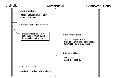
Figure 19 – Obtaining and installing an Application Instance Certificate
Figure 19 above illustrates the interactions between the application, the Administrator and the Certificate Authority. The application is a OPC UA Application installed on a single machine. The Administrator is the person responsible for managing the machine and the OPC UA Application. The Certificate Authority is an entity that can issue digital Certificates that meet the requirements of the organization deploying the OPC UA Application.
OPC UA defines interfaces and workflows to register OPC UA Applications with a central discovery service and to execute the interaction necessary with a CertificateManager to issue the initial Certificate Authority signed Certificate, The CertificateManager interface includes features to get a TrustList and also Certificate updates from a central place. The Global Discovery Server (GDS) and CertificateManager functionality is defined in OPC 10000-12.
If the Administrator decides that a self-signed Certificate meets the security requirements for the organization, then the Administrator may skip Steps 3 through 5. Application vendors shall ensure that a Certificate is available after the installation process. Every OPC UA Application shall allow the Administrators to replace Application Instance Certificates with Certificates that meet their requirements.
When the Administrator requests a new Certificate from a Certificate Authority, the Certificate Authority may require that the Administrator provide proof of authorization to request Certificates for the organization that will own the Certificate. The exact mechanism used to provide this proof depends on the Certificate Authority.
Vendors should automate the process of acquiring Certificates from an authority using the CertificateManager defined in OPC 10000-12. If this is the case, the Administrator would still go through the steps illustrated in Figure 19, however, the installation program for the application would do them automatically and only prompt the Administrator to provide information about the application instance being installed.
Applications shall never communicate with another application that they do not trust. An Application decides if another application is trusted by checking whether the Application Instance Certificate for the other application is trusted. A Certificate is only trusted if its chain can be validated.
Applications shall rely on lists of Certificates provided by the Administrator to determine trust. There are two separate lists: a list of trusted Certificates and a list of issuer Certificates (i.e. CAs). The list of trusted Certificates may contain a Certificate issued to another Application or it may be a Certificate belonging to a CA. The list of issuer Certificates contains CA Certificates needed for chain validation that are not in the list of trusted Certificates.
When building a chain each Certificate in the chain shall be validated back to a CA with a self-signed Certificate (a.k.a. a root CA). If any validation error occurs then the trust check fails. Some validation errors are non-critical which means they can be suppressed by a user of an Application with the appropriate privileges. Suppressed validation errors are always reported via auditing (i.e. an appropriate Audit event is raised).
Determining trust requires access to all Certificates in the chain. These Certificates may be stored locally or they may be provided with the application Certificate. Processing fails with Bad_SecurityChecksFailed if an element in the chain cannot be found. A Certificate is trusted if the Certificate or at least one of the Certificates in the chain are in the list of trusted Certificates for the Application and the chain is valid.
Table 106 specifies the steps used to validate a Certificate in the order that they shall be followed. These steps are repeated for each Certificate in the chain. Each validation step has a unique error status and audit event type that shall be reported if the check fails. The audit event is in addition to any audit event that was generated for the particular Service that was invoked. The Service audit event in its message text shall include the audit EventId of the AuditCertificateEventType (for more details, see 6.5). Processing halts if an error occurs, unless it is non-critical and it has been suppressed.
ApplicationInstanceCertificates shall not be used in a Client or Server until they have been evaluated and marked as trusted. This can happen automatically by a PKI trust chain or in an offline manner where the Certificate is marked as trusted by an administrator after evaluation.
Table 106 – Certificate validation steps
|
Step |
Error/AuditEvent |
Description |
|
Certificate Structure |
Bad_CertificateInvalid Bad_SecurityChecksFailed AuditCertificateInvalidEventType |
The Certificate structure is verified. This error may not be suppressed. If this check fails on the Server side, the error Bad_SecurityChecksFailed shall be reported back to the Client. |
|
Build Certificate Chain |
Bad_CertificateChainIncomplete Bad_SecurityChecksFailed AuditCertificateInvalidEventType |
The trust chain for the Certificate is created. An error during the chain creation may not be suppressed. If this check fails on the Server side, the error Bad_SecurityChecksFailed shall be reported back to the Client. |
|
Signature |
Bad_CertificateInvalid Bad_SecurityChecksFailed AuditCertificateInvalidEventType |
A Certificate with an invalid signature shall always be rejected. A Certificate signature is invalid if the Issuer Certificate is unknown. A self-signed Certificate is its own issuer. If this check fails on the Server side, the error Bad_SecurityChecksFailed shall be reported back to the Client. |
|
Security Policy Check |
Bad_CertificatePolicyCheckFailed Bad_SecurityChecksFailed AuditCertificateInvalidEventType |
A Certificate signature shall comply with the CertificateSignatureAlgorithm, MinAsymmetricKeyLength and MaxAsymmetricKeyLength requirements for the used SecurityPolicy defined in OPC 10000-7. If this check fails on the Server side, the error Bad_SecurityChecksFailed shall be reported back to the Client. This error may be suppressed. |
|
Trust List Check |
Bad_CertificateUntrusted Bad_SecurityChecksFailed AuditCertificateUntrustedEventType |
If the Application Instance Certificate is not trusted and none of the CA Certificates in the chain is trusted, the result of the Certificate validation shall be Bad_CertificateUntrusted. If this check fails on the Server side, the error Bad_SecurityChecksFailed shall be reported back to the Client. |
|
Validity Period |
Bad_CertificateTimeInvalid Bad_CertificateIssuerTimeInvalid AuditCertificateExpiredEventType |
The current time shall be after the start of the validity period and before the end. This error may be suppressed. |
|
Host Name |
Bad_CertificateHostNameInvalid AuditCertificateDataMismatchEventType |
The HostName in the URL used to connect to the Server shall be the same as one of the HostNames specified in the Certificate. This check is skipped for CA Certificates. This check is skipped for Server side validation. This error may be suppressed. |
|
URI |
Bad_CertificateUriInvalid AuditCertificateDataMismatchEventType |
Application and Software Certificates contain an application or product URI that shall match the URI specified in the ApplicationDescription provided with the Certificate. This check is skipped for CA Certificates. This error may not be suppressed. The gatewayServerUri is used to validate an Application Certificate when connecting to a Gateway Server (see 7.2). |
|
Certificate Usage |
Bad_CertificateUseNotAllowed Bad_CertificateIssuerUseNotAllowed AuditCertificateMismatchEventType |
Each Certificate has a set of uses for the Certificate (see OPC 10000-6). These uses shall match use requested for the Certificate (i.e. Application, Software or CA). This error may be suppressed unless the Certificate indicates that the usage is mandatory. |
|
Find Revocation List |
Bad_CertificateRevocationUnknown Bad_CertificateIssuerRevocationUnknown AuditCertificateRevokedEventType |
Each CA Certificate may have a revocation list. This check fails if this list is not available (i.e. a network interruption prevents the application from accessing the list). No error is reported if the Administrator disables revocation checks for a CA Certificate. This error may be suppressed. Bad_SecurityChecksFailed should be reported back to the Client. |
|
Revocation Check |
Bad_CertificateRevoked Bad_CertificateIssuerRevoked AuditCertificateRevokedEventType |
The Certificate has been revoked and may not be used. This error may not be suppressed. If this check fails on the Server side, the error Bad_SecurityChecksFailed shall be reported back to the Client. |
Certificates are usually placed in a central location called a CertificateStore. Figure 20 illustrates the interactions between the Application, the Administrator and the CertificateStore. The CertificateStore could be on the local machine or in some central server. The exact mechanisms used to access the CertificateStore depend on the application and PKI environment set up by the Administrator.
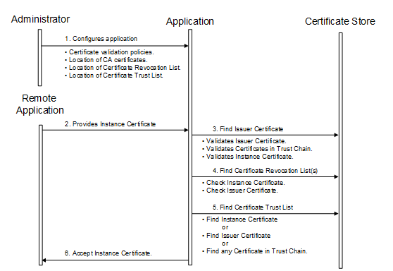
Figure 20 – Determining if an Application Instance Certificate is trusted
All OPC UA Applications shall establish a SecureChannel before creating a Session. This SecureChannel requires that both applications have access to Certificates that can be used to encrypt and sign Messages exchange. The Application Instance Certificates installed by following the process described in 6.1.2 may be used for this purpose.
The steps involved in establishing a SecureChannel are shown in Figure 21.
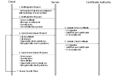
Figure 21 – Establishing a SecureChannel
Figure 21 assumes Client and Server have online access to a CertificateAuthority (CA). If online access is not available and if the administrator has installed the CA public key on the local machine, then the Client and Server shall still validate the application Certificates using that key. The figure shows only one CA, however, there is no requirement that the Client and Server Certificates be issued by the same authority. A self-signed Application Instance Certificate does not need to be verified with a CA. Any Certificate shall be rejected if it is not in a TrustList provided by the administrator.
Both the Client and Server shall have a list of Certificates that they have been configured to trust (sometimes called the Certificate Trust List or CTL). These trusted Certificates may be Certificates for Certificate Authorities or they may be OPC UA Application Instance Certificates. OPC UA Applications shall be configured to reject connections with applications that do not have a trusted Certificate.
Certificates can be compromised, which means they should no longer be trusted. Administrators can revoke a Certificate by removing it from the TrustList for all applications or the CA can add the Certificate to the Certificate Revocation List (CRL) for the Issuer Certificate. Administrators may save a local copy of the CRL for each Issuer Certificate when online access is not available.
A Client does not need to call GetEndpoints each time it connects to the Server. This information should change rarely and the Client can cache it locally. If the Server rejects the OpenSecureChannel request the Client should call GetEndpoints and make sure the Server configuration has not changed.
There are two security risks which a Client shall be aware of when using the GetEndpoints Service. The first could come from a rogue Discovery Server that tries to direct the Client to a rogue Server. For this reason the Client shall verify that the ServerCertificate in the EndpointDescription is a trusted Certificate before it calls CreateSession.
The second security risk comes from a third party that alters the contents of the EndpointDescriptions as they are transferred over the network back to the Client. The Client protects itself against this by comparing the list of EndpointDescriptions returned from the GetEndpoints Service with list returned in the CreateSession response.
The exact mechanisms for using the SecurityToken to sign and encrypt Messages exchanged over the SecureChannel are described in OPC 10000-6. The process for renewing tokens is also described in detail in OPC 10000-6.
In many cases, the Certificates used to establish the SecureChannel will be the Application Instance Certificates. However, some Communication Stacks might not support Certificates that are specific to a single application. Instead, they expect all communication to be secured with a Certificate specific to a user or the entire machine. For this reason, OPC UA Applications will need to exchange their Application Instance Certificates when creating a Session.
Once an OPC UA Client has established a SecureChannel with a Server it can create an OPC UA Session.
The steps involved in establishing a Session are shown in Figure 22.
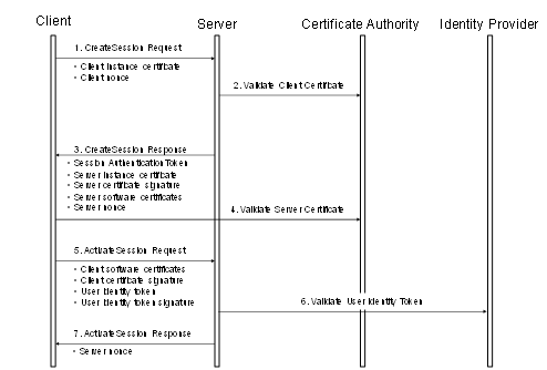
Figure 22 – Establishing a Session
Figure 22 illustrates the interactions between a Client, a Server, a Certificate Authority (CA) and an identity provider. The CA is responsible for issuing the Application Instance Certificates. If the Client or Server does not have online access to the CA, then they shall validate the Application Instance Certificates using the CA public key that the administrator shall install on the local machine.
The identity provider may be a central database that can verify that user token provided by the Client. This identity provider may also tell the Server which access rights the user has. The identity provider depends on the user identity token. It could be a Certificate Authority, an Authorization Service or a proprietary database of some sort.
The Client and Server shall prove possession of their Application Instance Certificates by signing the Certificates with a nonce appended. The exact mechanism used to create the proof of possession signatures is described in 5.7.2. Similarly, the Client shall prove possession by either providing a secret like a password in the user identity token or by creating a signature with the secret associated with a user identity token like X.509 v3.
Once an OPC UA Client has established a Session with a Server it can change the user identity associated with the Session by calling the ActivateSession service.
The steps involved in impersonating a user are shown in Figure 23. The access of the Server to the identity provider is Server-internal and it may be just an access to an internal user database.
Figure 23 – Impersonating a User
ApplicationInstanceCertificates or UserIdentityTokens may expire, get invalid or may be rejected on Client or Server side.
ApplicationInstanceCertificates verification shall be executed every time the SecurityToken is renewed for a SecureChannel. OPC UA Applications may do additional verifications between SecurityToken renews e.g. if the TrustList is updated from a GDS.
If the SecureChannel does not use ApplicationInstanceCertificates, the OPC UA Application should execute ApplicationInstanceCertificate checks for the Session at a rate used for SecureChannel renewals.
The recovery mechanisms for ApplicationInstanceCertificate replacement scenarios are described in 6.7.
OPC UA Application should have internal notification mechanisms to get informed about removal of user identities or should frequently check if the UserIdentityTokens is still valid or if the authorization for a UserIdentityTokens was changed.
Authorization Services provide Access Tokens to Clients on behalf of Users that they pass to a Server to be granted access to resources.
In a basic model (as shown in Figure 22) the Server is responsible for authorization (i.e. deciding what a user can do) while a separate identity provider (e.g. the operating system) is responsible for authentication (deciding who the user is).
In more complex models, the Server relies on external Authorization Services to provide some of its authorization requirements. These Authorization Services act in concert with an external identity provider which validates the user credentials before the external Authorization Service creates an Access Token that tells the Server what the user is a allowed to do. The Client interactions with these services may be indirect as shown in 6.2.2 or direct as shown in 6.2.3.
Even when the Server requires the Client to use an external Authorization Service the Server is still responsible for managing and enforcing the Permissions assigned to Nodes in its Address Space. The clauses below discuss the use of an external Authorization Service in more detail.
Authorization Services (AS) provide access to identity providers which can validate the credentials provided by Clients. They then provide tokens which can be passed to a Server instead of the credentials. These tokens are passed as an IssuedIdentityToken defined in 7.41.6.
The protocol to request tokens depends on the Authorization Service (AS). Common protocols include OAuth2 and OPC UA. OAuth2 supports claims based authorization as described in OPC 10000-2.
Servers publish the Authorization Services (AS) they support in the UserTokenPolicies list return with GetEndpoints. The IssuedTokenType field specifies the protocol used to communicate with the AS. The IssuerEndpointUrl field contains the information needed by the Client to connect to the AS using the protocol required by the AS.
The basic handshake is shown in Figure 24.
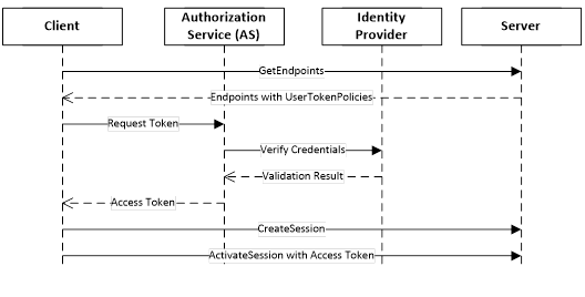
Figure 24 – Indirect handshake with an Identity Provider
Authorization Services require that Servers be registered with them because the Access Tokens can only be used with a single Server. This can introduce a lot of complexity for administrators. One way to reduce this complexity is to leverage the Server information that is already managed by a Global Discovery Service (GDS) described in OPC 10000-12. In this model the user identities are still managed by a central Authorization Service. The interactions are shown in Figure 25.
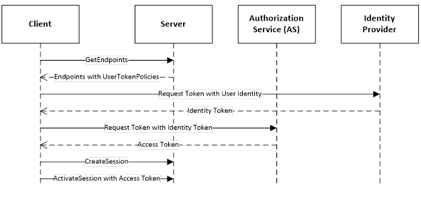
Figure 25 – Direct handshake with an Identity Provider
The UserTokenPolicy returned from the Server provides the URL of the Authorization Service and the identity provider. If the Application Authorization Service is linked with the GDS, it knows of all Servers which have been issued Certificates. The ApplicationUri is used as the identifier for the Server passed to the AS. The identity provider is responsible for managing users known to the system. It validates the credentials provided by the Client and returns an Identity Access Token which identifies the user. The Identity Access Token is passed to the Application Authorization Service which validates the Client and Server applications and creates a new Access Token that can be used to access the Server.
The Session-less Service invocation is introduced for Services, such as Read, Write or Call, that do not require any caller specific state information. It is accessible through the SessionlessInvoke Service which provides the context information required to call Services without a Session.
Session-less invocation is limited to Services of the View Service Set (with exception of RegisterNodes and UnregisterNodes), Attribute Service Set, Method Service Set, NodeManagement Service Set and Query Service Set. If Session-less Service invocation is supported by a Server, all Services belonging to these Service Sets that are supported by a Server via a Session shall also be supported via the SessionlessInvoke Service.
Session-less Services are invoked via a SecureChannel using the Access Token returned from the Authorization Service as the authenticationToken in the requestHeader. The SecureChannel shall have encryption enabled to prevent eavesdroppers from seeing the Access Token. The Access Token provides the user authentication. If application authentication through the SecureChannel is sufficient, Servers may not require the Access Token and assume an anonymous user. In this case the authenticationToken shall be null.
The SessionlessInvoke Messages are just an envelope for the Service to invoke and do not have a RequestHeader and ResponseHeader like other Services. Those parameters are already part of the body which contains the Message for the Service to invoke.
Any Endpoint used for normal communication could be used for Session-less invocation provided the Endpoint supports encryption. The Server returns Bad_ServiceUnsupported if it does not support Session-less invocation for the request specified in the body. If it supports invocation but not with the combination of Endpoint and security settings used it returns Bad_SecurityModeInsufficient.
Servers may expose Endpoints which are only for use with Session-less invocation. These Endpoints shall support GetEndpoints and FindServers in addition to the SessionlessInvoke Service. The Server returns Bad_ServiceUnsupported for the other Services.
A Session ensures that a namespace index or a server index does not change during the lifetime of a Session. This cannot be ensured between Session-less Services invocations. There are two options to ensure the namespace indices in the call match the expected namespace URIs in the Server. One option for the caller is to provide the list of namespace URIs used to build the namespace indices. This works best for single Session-less Service invocations. The second option is to provide the UrisVersion to ensure consistency of namespace arrays between Client and Server. The UrisVersion is first read from the Server together with the NamespaceArray and ServerArray. This reduces the overhead per call for a sequence of Session-less Service invocations.
Table 107 defines the parameters for the Service.
Table 107 – SessionlessInvoke Service Parameters
|
Name |
Type |
Description |
|
Request |
|
|
|
urisVersion |
VersionTime |
The version of the NamespaceArray and the ServerArray used for the Service invocation. The version shall match the value of the UrisVersion Property that defines the version for the URI lists in the NamespaceArray and the ServerArray Properties defined in OPC 10000-5. If the urisVersion parameter does not match the Server's UrisVersion Property, the Server shall return Bad_VersionTimeInvalid. In this case the Client shall read the UrisVersion, NamespaceArray and the ServerArray from the Server Object to repeat the Service invocation with the right version. The VersionTime DataType is defined in 7.44. If the value is 0, the parameter is ignored and the URIs are defined by the namespaceUris and serverUris parameters in request and response. If the value is non-zero, the namespaceUris and serverUris parameters in the request are ignored by the Server and set to null or empty arrays in the response. |
|
namespaceUris [] |
String |
A list of URIs referenced by NodeIds or QualifiedNames in the request. NamespaceIndex 0 shall not be in this list. The first entry in this list is NamespaceIndex 1. The parameter shall be ignored by the Server if the urisVersion is not 0. |
|
serverUris [] |
String |
A list of URIs referenced by ExpandedNodeIds in the request. ServerIndex 0 shall not be in this list. The first entry in this list is ServerIndex 1. The parameter shall be ignored by the Server if the urisVersion is not 0. |
|
localeIds [] |
LocaleId |
List of locale ids to use. See locale negotiation in 5.4 which applies to this Service. |
|
serviceId |
UInt32 |
The numeric identifier assigned to the Service request DataType NodeId describing the body. |
|
body |
* |
The body of the request. The body is an embedded structure containing the corresponding Service request for the serviceId. |
|
Response |
|
|
|
namespaceUris [] |
String |
A list of URIs referenced by NodeIds or QualifiedNames in the response. NamespaceIndex 0 shall not be in this list. The first entry in this list is NamespaceIndex 1. An empty array shall be returned if the urisVersion is not 0. |
|
serverUris [] |
String |
A list of URIs referenced by ExpandedNodeIds in the response. ServerIndex 0 shall not be in this list. The first entry in this list is ServerIndex 1. An empty array shall be returned if the urisVersion is not 0. |
|
serviceId |
UInt32 |
The numeric identifier assigned to the Service response DataType NodeId describing the body. |
|
body |
* |
The body of the response. The body is an embedded structure containing the corresponding Service response for the serviceId. |
Table 108 defines the Service results specific to this Service. Common StatusCodes are defined in Table 182.
Table 108 – SessionlessInvoke Service Result Codes
|
Symbolic Id |
Description |
|
Bad_VersionTimeInvalid |
The provided version time is no longer valid. |
Note Details on SoftwareCertificates will be defined in a future version of this document.
Auditing is a requirement in many systems. It provides a means of tracking activities that occur as part of normal operation of the system. It also provides a means of tracking abnormal behaviour. It is also a requirement from a security standpoint. For more information on the security aspects of auditing, see OPC 10000-2. Subclause 6.5 describes what is expected of an OPC UA Server and Client with respect to auditing and it details the audit requirements for each service set. Auditing can be accomplished using one or both of the following methods:
a) The OPC UA Application that generates the audit event can log the audit entry in a log file or other storage location;
b) The OPC UA Server that generates the audit event can publish the audit event using the OPC UA event mechanism. This allows an external OPC UA Client to subscribe to and log the audit entries to a log file or other storage location.
Each OPC UA Service request contains a string parameter that is used to carry an audit record id. A Client or any Server operating as a Client, such as an aggregating Server, can create a local audit log entry for a request that it submits. This parameter allows this Client to pass the identifier for this entry with the request. If this Server also maintains an audit log, it should include this id in its audit log entry that it writes. When this log is examined and that entry is found, the examiner will be able to relate it directly to the audit log entry created by the Client. This capability allows for traceability across audit logs within a system.
A Server that maintains an audit log shall provide the audit log entries via Event Messages. The AuditEventType and its sub-types are defined in OPC 10000-3. An audit Event Message also includes the audit record Id. The details of the AuditEventType and its subtypes are defined in OPC 10000-5. A Server that is an aggregating Server that supports auditing shall also subscribe for audit events for all of the Servers that it is aggregating (assuming they provide auditing). The combined stream should be available from the aggregating Server.
This Service Set can be separated into two groups: Services that are called by OPC UA Clients and Services that are invoked by OPC UA Servers. The FindServers and GetEndpoints Services that are called by OPC UA Clients may generate audit entries for failed Service invocations. The RegisterServer Service that is invoked by OPC UA Servers shall generate audit entries for all new registrations and for failed Service invocations. These audit entries shall include the Server URI, Server names, Discovery URIs and isOnline status. Audit entries should not be generated for RegisterServer invocation that does not cause changes to the registered Servers.
All Services in this Service Set for Servers that support auditing may generate audit entries and shall generate audit Events for failed service invocations and for successful invocation of the OpenSecureChannel and CloseSecureChannel Services. The Client generated audit entries should be setup prior to the actual call, allowing the correct audit record Id to be provided. The OpenSecureChannel Service shall generate an audit Event of type AuditOpenSecureChannelEventType or a subtype of it for the requestType ISSUE. Audit Events for the requestType RENEW are only created if the renew fails. The CloseSecureChannel service shall generate an audit Event of type AuditChannelEventType or a subtype of it. Both of these Event types are subtypes of the AuditChannelEventType. See OPC 10000-5 for the detailed assignment of the SourceNode, the SourceName and additional parameters. For the failure cases the Message for Events of this type should include a description of why the service failed. This description should be more detailed than what was returned to the Client. From a security point of view a Client only needs to know that it failed, but from an Auditing point of view the exact details of the failure need to be known.
In the case of Certificate validation errors the CertificateErrorEventId of the AuditOpenSecureChannelEventType should include the audit EventId of the specific AuditCertificateEventType that was generated to report the Certificate error. The AuditCertificateEventType shall also contain the detailed Certificate validation error. The additional parameters should include the details of the request. It is understood that these events may be generated by the underlying Communication Stacks in many cases, but they shall be made available to the Server and the Server shall report them.
All Services in this Service Set for Servers that support auditing may generate audit entries and shall generate audit Events for both successful and failed Service invocations. These Services shall generate an audit Event of type AuditSessionEventType or a subtype of it. In particular, they shall generate the base EventType or the appropriate subtype, depending on the service that was invoked. The CreateSession service shall generate AuditCreateSessionEventType events or sub-types of it. The ActivateSession service shall generate AuditActivateSessionEventType events or subtypes of it. When the ActivateSession Service is called to change the user identity then the Server shall generate AuditActivateSessionEventType events or subtypes of it. The CloseSession service shall generate AuditSessionEventType events or subtypes of it. It shall always be generated if a Session is terminated like Session timeout expiration or Server shutdown. The SourceName for Events of this type shall be “Session/Timeout” for a Session timeout, “Session/CloseSession” for a CloseSession Service call and “Session/Terminated” for all other cases. See OPC 10000-5 for the detailed assignment of the SourceNode, the SourceName and additional parameters. For the failure case the Message for Events of this type should include a description of why the Service failed. The additional parameters should include the details of the request.
This Service Set shall also generate additional audit events in the cases when Certificate validation errors occur. These audit Events are generated in addition to the AuditSessionEventType Events. See OPC 10000-3 for the definition of AuditCertificateEventType and its subtypes.
For Clients, that support auditing, accessing the services in the Session Service Set shall generate audit entries for both successful and failed invocations of the Service. These audit entries should be setup prior to the actual Service invocation, allowing the invocation to contain the correct audit record id.
All Services in this Service Set for Servers that support auditing may generate audit entries and shall generate audit Events for both successful and failed Service invocations. These Services shall generate an audit Event of type AuditNodeManagementEventType or subtypes of it. See OPC 10000-5 for the detailed assignment of the SourceNode, the SourceName and additional parameters. For the failure case, the Message for Events of this type should include a description of why the service failed. The additional parameters should include the details of the request.
For Clients that support auditing, accessing the Services in the NodeManagement Service Set shall generate audit entries for both successful and failed invocations of the Service. All audit entries should be setup prior to the actual Service invocation, allowing the invocation to contain the correct audit record id.
The Write or HistoryUpdate Services in this Service Set for Servers that support auditing may generate audit entries and shall generate audit Events for both successful and failed Service invocations. These Services shall generate an audit Event of type AuditUpdateEventType or subtypes of it. In particular, the Write Service shall generate an audit event of type AuditWriteUpdateEventType or a subtype of it. The HistoryUpdate Service shall generate an audit Event of type AuditHistoryUpdateEventType or a subtype of it. Three subtypes of AuditHistoryUpdateEventType are defined as AuditHistoryEventUpdateEventType, AuditHistoryValueUpdateEventType and AuditHistoryDeleteEventType. The subtype depends on the type of operation being performed, historical event update, historical data value update or a historical delete. See OPC 10000-5 for the detailed assignment of the SourceNode, the SourceName and additional parameters. For the failure case the Message for Events of this type should include a description of why the Service failed. The additional parameters should include the details of the request.
The Read and HistoryRead Services may generate audit entries and audit Events for failed Service invocations. These Services should generate an audit Event of type AuditEventType or a subtype of it. See OPC 10000-5 for the detailed assignment of the SourceNode, SourceName and additional parameters. The Message for Events of this type should include a description of why the Service failed.
For Clients that support auditing, accessing the Write or HistoryUpdate services in the Attribute Service Set shall generate audit entries for both successful and failed invocations of the Service. Invocations of the other Services in this Service Set may generate audit entries. All audit entries should be setup prior to the actual Service invocation, allowing the invocation to contain the correct audit record id.
All Services in this Service Set for Servers that support auditing may generate audit entries and shall generate audit Events for both successful and failed service invocations if the invocation modifies the AddressSpace, writes a value or modifies the state of the system (alarm acknowledge, batch sequencing or other system changes). These method calls shall generate an audit Event of type AuditUpdateMethodEventType or subtypes of it. Methods that do not modify the AddressSpace, write values or modify the state of the system may generate events. See OPC 10000-5 for the detailed assignment of the SourceNode, SourceName and additional parameters.
For Clients that support auditing, accessing the Method Service Set shall generate audit entries for both successful and failed invocations of the Service, if the invocation modifies the AddressSpace, writes a value or modifies the state of the system (alarm acknowledge, batch sequencing or other system changes). Invocations of the other Methods may generate audit entries. All audit entries should be setup prior to the actual Service invocation, allowing the invocation to contain the correct audit record id.
All of the Services in these four Service Sets only provide the Client with information, with the exception of the TransferSubscriptions Service in the Subscription Service Set. In general, these services will not generate audit entries or audit Event Messages. The TransferSubscriptions Service shall generate an audit Event of type AuditSessionEventType or subtypes of it for both successful and failed Service invocations. See OPC 10000-5 for the detailed assignment of the SourceNode, the SourceName and additional parameters. For the failure case, the Message for Events of this type should include a description of why the service failed.
For Clients that support auditing, accessing the TransferSubscriptions Service in the Subscription Service Set shall generate audit entries for both successful and failed invocations of the Service. Invocations of the other Services in this Service Set do not require audit entries. All audit entries should be setup prior to the actual Service invocation, allowing the invocation to contain the correct audit record id.
OPC UA enables Servers, Clients and networks to be redundant. OPC UA provides the data structures and Services by which Redundancy may be achieved in a standardized manner.
Server Redundancy allows Clients to have multiple sources from which to obtain the same data. Server Redundancy can be achieved in multiple manners, some of which require Client interaction, others that require no interaction from a Client. Redundant Servers could exist in systems without redundant networks or Clients. Redundant Servers could also coexist in systems with network and Client Redundancy. Server Redundancy is formally defined in 6.6.2.
Client Redundancy allows identically configured Clients to behave as if they were single Clients, but not all Clients are obtaining data at a given time. Ideally there should be no loss of information when a Client Failover occurs. Redundant Clients could exist in systems without redundant networks or Servers. Redundant Clients could also coexist in systems with network and Server Redundancy. Client Redundancy is formally defined in 6.6.3.
Network Redundancy allows a Client and Server to have multiple communication paths to obtain the same data. Redundant networks could exist in systems without redundant Servers or Clients. Redundant networks could also coexist in systems with Client and Server Redundancy. Network Redundancy is formally defined in 6.6.4.
There are two general modes of Server Redundancy, transparent and non-transparent.
In transparent Redundancy the Failover of Server responsibilities from one Server to another is transparent to the Client. The Client is unaware that a Failover has occurred and the Client has no control over the Failover behaviour. Furthermore, the Client does not need to perform any actions to continue to send or receive data.
In non-transparent Redundancy the Failover from one Server to another and actions to continue to send or receive data are performed by the Client. The Client shall be aware of the RedundantServerSet and shall perform the required actions to benefit from the Server Redundancy.
The ServerRedundancy Object defined in OPC 10000-5 indicates the mode supported by the Server. The ServerRedundancyType ObjectType and its subtypes TransparentRedundancyType and NonTransparentRedundancyType defined in OPC 10000-5 specify information for the supported Redundancy mode.
OPC UA Servers that are part of a RedundantServerSet have certain AddressSpace requirements. These requirements allow a Client to consistently access information from Servers in a RedundantServerSet and to make intelligent choices related to the health and availability of Servers in the RedundantServerSet.
Servers in the RedundantServerSet shall have an identical AddressSpace including:
· identical NodeIds
· identical browse paths and structure of the AddressSpace
· identical logic for setting the ServiceLevel
The only Nodes that can differ between Servers in a RedundantServerSet are the Nodes that are in the local Server namespace like the Server diagnostic Nodes. A Client that fails over shall not be required to translate browse paths or otherwise resolve NodeIds. Servers are allowed to add and delete Nodes as long as all Servers in the RedundantServerSet will be updated with the same Node changes.
There are other important considerations for a redundant system regarding synchronization:
• EventIds: Each UA Server in a Transparent (6.6.2.3) and HotAndMirrored (6.6.2.4.5.5) RedundantServerSet shall synchronize EventIds to prevent a Client from mistakenly processing the same event multiple times simply because the EventIds are different. This is very important for Alarms & Conditions. For Cold, Warm, and Hot RedundantServerSets Clients shall be able to handle EventIds that are not synchronized. Following any Failover the Client shall call ConditionRefresh defined in OPC 10000-9.
• Timestamp (Source/Server): If a Server is exposing data from a downstream device (PLC, DCS etc.) then the SourceTimestamp and ServerTimestamp reported by all redundant Servers should match as closely as possible. Clients should favour the use of the SourceTimestamp.
• ContinuationPoints: Behaviour of continuation points does not change, in that Clients shall be prepared for lost continuation points. Servers in Transparent and HotAndMirrored Redundancy sets shall synchronize continuation points and they may do so in other modes.
To a Client the transparent RedundantServerSet appears as if it is just a single Server and the Client has no Failover actions to perform. All Servers in the RedundantServerSet have an identical ServerUri and an identical EndpointUrl.
Figure 26 shows a typical transparent Redundancy setup.
Figure 26 – Transparent Redundancy setup example
For transparent Redundancy, OPC UA provides data structures to allow Clients to identify which Servers are in the RedundantServerSet, the ServiceLevel of each Server, and which Server is currently responsible for the Client Session. This information is specified in TransparentRedundancyType ObjectType defined in OPC 10000-5. Since the ServerUri is identical for all Servers in the RedundantServerSet, the Servers are identified with a ServerId contained in the information provided in the TransparentRedundancyType Object.
In transparent Redundancy, a Client is not able to control which physical Server it actually connects to. Failover is controlled by the RedundantServerSet and a Client is also not able to actively Failover to another Server in the RedundantServerSet.
All OPC UA interactions within a given Session shall be supported by one Server and the Client is able to identify which Server that is, allowing a complete audit trail for the data. It is the responsibility of the Servers to ensure that information is synchronized between the Servers. A functional Server will take over the Session and Subscriptions from the Failed Server. Failover may require a reconnection of the Client’s SecureChannel but the EndpointUrl of the Server and the ServerUri shall not change. The Client shall be able to continue communication with the Sessions and Subscriptions created on the previously used Server.
Figure 26 provides an abstract view of a transparent RedundantServerSet. The two or more Servers in the RedundantServerSet share a virtual network address and therefore all Servers have the identical EndpointUrl. This includes all other EndpointDescriptions content like identical Certificates and security settings. How this virtual network address is created and managed is vendor specific. There may be special hardware that mediates the network address displayed to the rest of the network. There may be custom hardware, where all components are redundant and Failover at a hardware level automatically. There may even be software based systems where all the transparency is governed completely by software.
For non-transparent Redundancy, OPC UA provides the data structures to allow the Client to identify what Servers are available in the RedundantServerSet and also Server information which tells the Client what modes of Failover the Server supports. This information allows the Client to determine what actions it may need to take in order to accomplish Failover. This information is specified in NonTransparentRedundancyType ObjectType defined in OPC 10000-5.
The Servers in the non-transparent RedundantServerSet shall use the ServerCapability NTRS defined in OPC 10000-12 for discovery including the registration with a GlobalDiscoveryServer.
Figure 27 shows a typical non-transparent Redundancy setup.
Figure 27 – Non-Transparent Redundancy setup
For non-transparent Redundancy, the Servers will have unique IP addresses and unique ApplicationUris. The Server also has additional Failover modes of Cold, Warm, Hot and HotAndMirrored. The Client shall be aware of the RedundantServerSet and shall be required to perform some actions depending on the Failover mode. These actions are described in Table 111 and additional examples and explanations are provided in 6.6.2.4.5.2.for Cold, 6.6.2.4.5.3 for Warm, 6.6.2.4.5.4 for Hot and 6.6.2.4.5.5 for HotAndMirrored.
A Client needs to be able to expect that the SourceTimestamp associated with a value is approximately the same from all Servers in the RedundantServerSet for the same value.
The ServiceLevel provides information to a Client regarding the health of a Server and its ability to provide data. See OPC 10000-5 for a formal definition for ServiceLevel. The ServiceLevel is a byte with a range of 0 to 255, where the values fall into the sub-ranges defined in Table 109.
The algorithm used by a Server to determine its ServiceLevel within each sub-range is Server specific. However, all Servers in a RedundantServerSet shall use the same algorithm to determine the ServiceLevel. All Servers, regardless of RedundantServerSet membership, shall adhere to the sub-ranges defined in Table 109.
Table 109 – ServiceLevel ranges
|
Sub-range |
Name |
Description |
|
0-0 |
Maintenance |
The Failed Server is in maintenance sub-range. Therefore, new Clients shall not connect and currently connected Clients shall disconnect. The Server should expose a target time at which the Clients are able to reconnect. See EstimatedReturnTime defined in OPC 10000-5 for additional information. A Server that has been set to Maintenance is typically undergoing some maintenance or updates. The main goal for the Maintenance ServiceLevel is to ensure that Clients do not generate load on the Server and allow time for the Server to complete any actions that are required. This load includes even simple connections attempts or monitoring of the ServiceLevel. The EstimatedReturnTime indicates when the Client should check to see if the Server is available. If updates or patches are taking longer than expected the Client may discover that the EstimatedReturnTime has been extended further into the future. If the Server does not provide the EstimatedReturnTime, or if the time has lapsed, the Client should use a much longer interval between reconnects to a Server in the Maintenance sub-range than its normal reconnect interval. |
|
1-1 |
NoData |
The Failed Server is not operational. Therefore, a Client is not able to exchange any information with it. The Server most likely has no data other than ServiceLevel, ServerStatus and diagnostic information available. A Failed Server in this sub-range has no data available. Clients may connect to it to obtain ServiceLevel, ServerStatus and other diagnostic information. If the underlying system has failed, typically the ServerStatus would indicate COMMUNICATION_FAULT. The Client may monitor this Server for a ServerStatus and ServiceLevel change, which would indicate that normal communication could be resumed. |
|
2-199 |
Degraded |
The Server is partially operational, but is experiencing problems such that portions of the AddressSpace are out of service or unavailable. An example usage of this ServiceLevel sub-range would be if 3 of 10 devices connected to a Server are unavailable. Servers that report a ServiceLevel in the Degraded sub-range are partially able to service Client requests. The degradation could be caused by loss of connection to underlying systems or functioning in a mode like a backup Server which results in less than full functionality being available. Alternatively, it could be that the Server is overloaded to the point that it is unable to reliably deliver data to Clients in a timely manner. If Clients are experiencing difficulties obtaining required data, they shall switch to another Server if any Servers in the Healthy range are available. If no Servers are available in the Healthy range, then Clients may switch to a Server with a higher ServiceLevel or one that provides the required data. Some Clients may also be configured for higher priority data and may check all Degraded Servers, to see if any of the Servers are able to report as good quality the high priority data, but this functionality would be Client specific. In some cases a Client may connect to multiple Degraded Servers to maximize the available information. |
|
200-255 |
Healthy |
The Server is fully operational. Therefore, a Client can obtain all information from this Server. The sub-range allows a Server to provide information that can be used by Clients to load balance. An example usage of this ServiceLevel sub-range would be to reflect the Server’s CPU load where data is delivered as expected. Servers in the Healthy ServiceLevel sub-range are able to deliver information in a timely manner. This ServiceLevel may change for internal Server reason or it may be used for load balancing described in 6.6.2.4.3. Client shall connect to the Server with the highest ServiceLevel. Once connected, the ServiceLevel may change, but a Client shall not Failover to a different Server as long as the ServiceLevel of the Server is accessible and in the Healthy sub-range. |
In systems where multiple Hot Servers (see 6.6.2.4.5.4) are available, the Servers in the RedundantServerSet can share the load generated by Clients by setting the ServiceLevel in the Healthy sub-range based on the current load. Clients are expected to connect to the Server with the highest ServiceLevel. Clients shall not Failover to a different Server in the RedundantServerSet of Servers as long as the Server is in the Healthy sub-range. This is the normal behaviour for all Clients, when communicating with redundant Servers. Servers can adjust their ServiceLevel based on the number of Clients that are connected, CPU loading, memory utilization, or any other Server specific criteria.
For example in a system with 3 Servers, all Servers are initially at ServiceLevel 255, but when a Client connects, the Server with the Client connection sets its level to 254. The next Client would connect to a different Server since both of the other Servers are still at 255.
It is up to the Server vendor to define the logic for spreading the load and the number of expected Clients, CPU load or other criteria on each Server before the ServiceLevel is decremented. It is envisioned that some Servers would be able to accomplish this without any communication between the Servers.
The Failover mode of a Server is provided in the ServerRedundancy Object defined in OPC 10000-5. The different Failover modes for non-transparent Redundancy are described in Table 110.
Table 110 – Server Failover modes
|
Name |
Description |
|
Cold |
Cold Failover mode is where only one Server can be active at a time. This may mean that redundant Servers are unavailable (not powered up) or are available but not running (PC is running, but application is not started) |
|
Warm |
Warm Failover mode is where the backup Server(s) can be active, but is not operating in a mode which delivers the same level of functionality available from the primary Server. For example it cannot connect to actual data points (typically, a system where the underlying devices are limited to a single connection). Underlying devices, such as PLCs, may have limited resources that permit a single Server connection. Therefore, only a single Server will be able to consume data. The ServiceLevel Variable defined in OPC 10000-5 and the sub-range defined in Table 109 indicates the ability of the Server to provide its data to the Client. The ServiceLevel of the primary Server will be in the Healthy ServiceLevel sub-range. The ServiceLevel of the available backup Server will be in the Degraded ServiceLevel sub-range. |
|
Hot |
Hot Failover mode is where all Servers are powered-on, and are up and running. In scenarios where Servers acquire data from a downstream device, such as a PLC, then one or more Servers are actively connected to the downstream device(s) in parallel. These Servers have minimal knowledge of the other Servers in their group and are independently functioning. When a Server fails or encounters a serious problem then its ServiceLevel drops. On recovery, the Server returns to the RedundantServerSet with an appropriate ServiceLevel to indicate that it is available. |
|
HotAndMirrored |
HotAndMirrored Failover mode is where Failovers are for Servers that are mirroring their internal states to all Servers in the RedundantServerSet and more than one Server can be active and fully operational. Mirroring state minimally includes Sessions, Subscriptions, registered Nodes, ContinuationPoints, sequence numbers, and sent Notifications. The ServiceLevel Variable defined in OPC 10000-5 should be used by the Client to find the Servers with the highest ServiceLevel to achieve load balancing. |
Each Server maintains a list of ServerUris for all redundant Servers in the RedundantServerSet. The list is provided together with the Failover mode in the ServerRedundancy Object defined in OPC 10000-5. To enable Clients to connect to all Servers in the list, each Server in the list shall provide the ApplicationDescription for all Servers in the RedundantServerSet through the FindServers Service. This information is needed by the Client to translate the ServerUri into information needed to connect to the other Servers in the RedundantServerSet. Therefore a Client needs to connect to only one of the redundant Servers to find the other Servers based on the provided information. A Client should persist information about other Servers in the RedundantServerSet.
Table 111 defines a list of Client actions for initial connections and Failovers.
Table 111 – Redundancy Failover actions
|
Failover mode and Client options |
Cold |
Warm |
Hot (a) |
Hot (b) |
HotAndMirrored |
|
On initial connection in addition to actions on Active Server: |
|
|
|
|
|
|
Connect to more than one OPC UA Server. |
|
X |
X |
X |
Optional for status check |
|
Create Subscriptions and add monitored items. |
|
X |
X |
X |
|
|
Activate sampling on the Subscriptions. |
|
|
X |
X |
|
|
Activate publishing. |
|
|
|
X |
|
|
At Failover: |
|
|
|
|
|
|
OpenSecureChannel to backup OPC UA Server |
X |
|
|
|
X |
|
CreateSession on backup OPC UA Server |
X |
|
|
|
|
|
ActivateSession on backup OPC UA Server |
X |
|
|
|
X |
|
Create Subscriptions and add monitored items. |
X |
|
|
|
|
|
Activate sampling on the Subscriptions. |
X |
X |
|
|
|
|
Activate publishing. |
X |
X |
X |
|
|
Clients communicating with a non-transparent RedundantServerSet of Servers require some additional logic to be able to handle Server failures and to Failover to another Server in the RedundantServerSet. Figure 28 provides an overview of the steps a Client typically performs when it is first connecting to a RedundantServerSet. The figure does not cover all possible error scenarios.
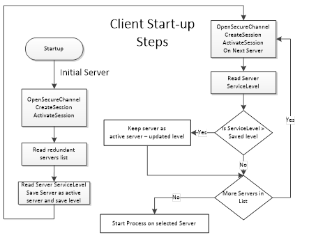
Figure 28 – Client Start-up steps
The initial Server may be obtained via standard discovery or from a persisted list of Servers in the RedundantServerSet. But in any case the Client needs to check which Server in the Server set it should connect to. Individual actions will depend on the Server Failover mode the Server provides and the Failover mode the Client will use.
Clients once connected to a redundant Server shall be aware of the modes of Failover supported by a Server since this support affects the available options related to Client behaviour. A Client may always treat a Server using a lesser Failover mode, i.e. for a Server that provides Hot Redundancy, a Client might connect and choose to treat it as if the Server was running in Warm Redundancy or Cold Redundancy. This choice is up to the Client. In the case of Failover mode HotAndMirrored, the Client shall not use Failover mode Hot or Warm as it would generate unnecessary load on the Servers.
A Cold Failover mode is where the Client can only connect to one Server at a time. When the Client loses connectivity with the Active Server it will attempt a connection to the redundant Server(s) which may or may not be available. In this situation the Client may need to wait for the redundant Server to become available and then create Subscriptions and MonitoredItems and activate publishing. The Client shall cache any information that is required related to the list of available Servers in the RedundantServerSet. Figure 29 illustrates the action a Client would take if it is talking to a Server using Cold Failover mode. The monitor connection logic is defined in 6.7.
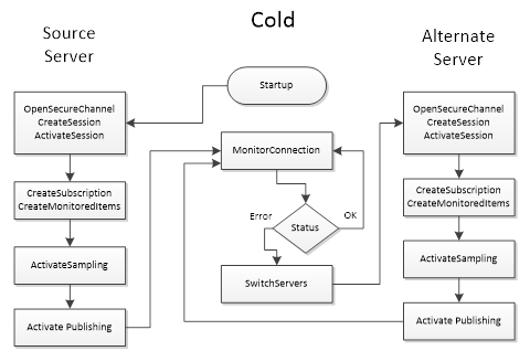
Figure 29 – Cold Failover
NOTE There may be a loss of data from the time the connection to the Active Server is interrupted until the time the Client gets Publish Responses from the backup Server.
A Warm Failover mode is where the Client should connect to one or more Servers in the RedundantServerSet primarily to monitor the ServiceLevel. A Client can connect and create Subscriptions and MonitoredItems on more than one Server, but sampling and publishing can only be active on one Server. However, the active Server will return actual data, whereas the other Servers in the RedundantServerSet will return an appropriate error for the MonitoredItems in the Publish response such as Bad_NoCommunication. The one Active Server can be found by reading the ServiceLevel Variable from all Servers. The Server with the highest ServiceLevel is the Active Server. For Failover the Client activates sampling and publishing on the Server with the highest ServiceLevel. Figure 30 illustrates the steps a Client would perform when communicating with a Server using Warm Failover mode. The monitor connection logic is defined in 6.7.
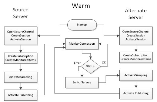
Figure 30 – Warm Failover
NOTE There may be a temporary loss of data from the time the connection to the Active Server is interrupted until the time the Client gets Publish Responses from the backup Server.
A Hot Failover mode is where the Client should connect to two or more Servers in the RedundantServerSet and to subscribe to the ServiceLevel variable defined in OPC 10000-5 to find the highest ServiceLevel to achieve load balancing; this means that Clients should issue Service requests such as Browse, Read, Write to the Server with the highest ServiceLevel. Subscription related activities will need to be invoked for each connected Server. Clients have the following choices for implementing Subscription behaviour in a Hot Failover mode:
a. The Client connects to multiple Servers and establishes Subscription(s) in each where only one is Reporting; the others are Sampling only. The Client should setup the queue size for the MonitoredItems such that it can buffer all changes during the Failover time. The Failover time is the time between the connection interruption and the time the Client gets Publish Responses from the backup Server. On a Failover the Client shall enable Reporting on the Server with the next highest availability.
b. The Client connects to multiple Servers and establishes Subscription(s) in each where all Subscriptions are Reporting. The Client is responsible for handling/processing multiple Subscription streams concurrently.
Figure 31 illustrate the functionality a Client would perform when communicating with a Server using Hot Failover mode (the figure include both (a) and (b) options). The monitor connection logic is defined in 6.7.
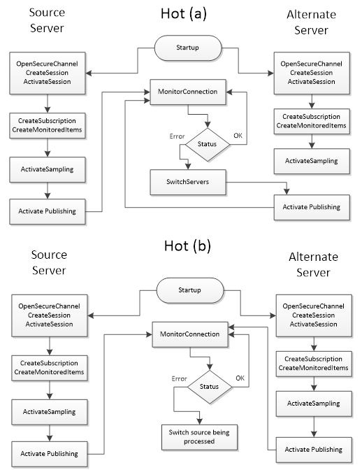
Figure 31 – Hot Failover
Clients are not expected to automatically switch over to a Server that has recovered from a failure, but the Client should establish a connection to it.
A HotAndMirrored Failover mode is where a Client only connects to one Server in the RedundantServerSet because the Server will share this session/state information with the other Servers. In order to validate the capability to connect to other redundant Servers it is allowed to create Sessions with other Servers and maintain the open connections by periodically reading the ServiceLevel. A Client shall not create Subscriptions on the backup Servers for status monitoring (to prevent excessive load on the Servers). This mode allows Clients to fail over without creating a new context for communication. On a Failover the Client will simply create a new SecureChannel on an alternate Server and then call ActivateSession; all Client activities (browsing, subscriptions, history reads, etc.) will then resume. Figure 32 illustrate the behaviour a Client would perform when communicating to a Server in HotAndMirrored Failover mode. The monitor connection logic is defined in 6.7.
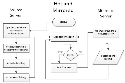
Figure 32 – HotAndMirrored Failover
This Failover mode is similar to the transparent Redundancy. The advantage is that the Client has full control over selecting the Server. The disadvantage is that the Client needs to be able to handle Failovers.
A vendor can use the non-transparent Redundancy features to create a Server proxy running on the Client machine to provide transparent Redundancy to the Client. This reduces the amount of functionality that needs to be designed into the Client and to enable simpler Clients to take advantage of non-transparent Redundancy. The Server proxy simply duplicates Subscriptions and modifications to Subscriptions, by passing the calls on to both Servers, but only enabling publishing and sampling on one Server. When the proxy detects a failure, it enables publishing and/or sampling on the backup Server, just as the Client would if it were a Redundancy aware Client.
Figure 33 shows the Server proxy used to provide transparent Redundancy.
Figure 33 – Server proxy for Redundancy
Client Redundancy is supported in OPC UA by the TransferSubscriptions Service and by exposing Client information in the Server diagnostic information. Since Subscription lifetime is not tied to the Session in which it was created, backup Clients may use standard diagnostic information available to monitor the active Client’s Session with the Server. Upon detection of an active Client failure, a backup Client would then instruct the Server to transfer the Subscriptions to its own session. If the Subscription is crafted carefully, with sufficient resources to buffer data during the change-over, data loss from a Client Failover can be prevented.
OPC UA does not provide a standardized mechanism for conveying the SessionId and SubscriptionIds from the active Client to the backup Clients, but as long as the backup Clients know the Client name of the active Client, this information is readily available using the SessionDiagnostics and SubscriptionDiagnostics portions of the ServerDiagnostics data. This information is available for authorized users and for the user active on the Session. TransferSubscriptions requires the same user on all redundant Clients to succeed.
Redundant networks can be used with OPC UA in either transparent or non-transparent Redundancy.
Network Redundancy can be combined with Server and Client Redundancy.
In the transparent network use-case a single Server Endpoint can be reached through different network paths. This case is completely handled by the network infrastructure. The selected network path and Failover are transparent to the Client and the Server. Transparent network Redundancy is illustrated in Figure 34.
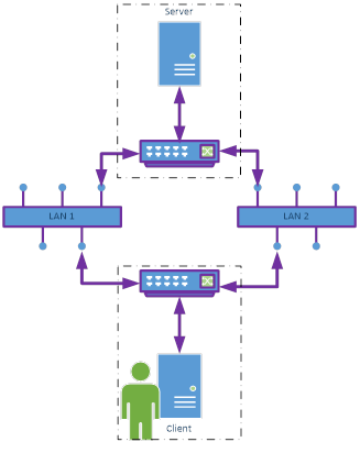
Figure 34 –
Transparent network Redundancy
Examples:
· A physical appliance/device such as a router or gateway which automatically changes the network routing to maintain communications.
· A virtual adapter which automatically changes the network adapter to maintain communications.
In the non-transparent network use-case the Server provides different Endpoints for the different network paths. This requires both the Server and the Client to support multiple network connections. In this case the Client is responsible for selecting the Endpoint and for Failover. For Failover the normal reconnect scenario described in 6.7 can be used. Only the SecureChannel is created with another Endpoint. Sessions and Subscriptions can be reused. Non-transparent network Redundancy is illustrated in Figure 35.
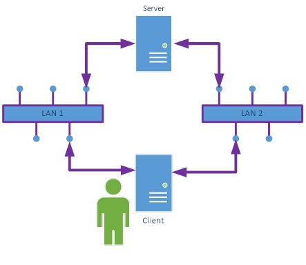
Figure 35 – Non-transparent network Redundancy
The information about the different network paths is specified in NonTransparentRedundancyType ObjectType defined in OPC 10000-5.
In redundant systems, it is common to require that a particular Server in the RedundantServerSet be taken out of the RedundantServerSet for a period of time. Some items that could cause this may include:
· Certificate update
· Security reconfiguration
· Rebooting or restarting of the machine for
o software updates and patches
o installation of new software
· Reconfiguration of the AddressSpace
The removal from the RedundantServerSet can be done through a complete shutdown or by setting the ServiceLevel of the Server to Maintenance sub-range. This can be done through a Server specific configuration tool or through the Method RequestServerStateChange on the ServerType. The Method is formally defined in OPC 10000-5.
This Method requires that the Client provide credentials with administrative rights on the Server.
After a Client establishes a connection to a Server and creates a Subscription, the Client monitors the connection status. Figure 36 shows the steps to connect a Client to a Server and the general logic for reconnect handling. Not all possible error scenarios are covered.
The preferred mechanism for a Client to monitor the connection status is through the keep-alive of the Subscription. A Client should subscribe for the State Variable in the ServerStatus to detect shutdown or other failure states. If no Subscription is created or the Server does not support Subscriptions, the connection can be monitored by periodically reading the State Variable.
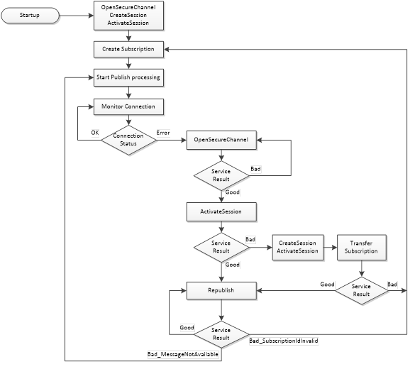
Figure 36 – Reconnect sequence
When a Client loses the connection to the Server, the goal is to reconnect without losing information. To do this the Client shall re-establish the connection by creating a new SecureChannel and activating the Session with the Service ActivateSession. If the OpenSecureChannel fails, the Client should delay the retry for a configurable time. The ActivateSession assigns the new SecureChannel to the existing Session and allows the Client to reuse the Session and Subscriptions in the Server. To re-establish the SecureChannel and activate the Session, the Client shall use the same security policy, application instance certificate and the same user credential used to create the original SecureChannel. This will result in the Client receiving data and event Notifications without losing information provided the queues in the MonitoredItems do not overflow.
The Client shall only create a new Session if ActivateSession fails. TransferSubscriptions is used to transfer the Subscription to the new Session. If TransferSubscriptions fails, the Client needs to create a new Subscription.
When the connection is lost, Publish responses may have been sent but not received by the Client.
After re-establishing the connection the Client shall call Republish in a loop, starting with the next expected sequence number and incrementing the sequence number until the Server returns the status Bad_MessageNotAvailable. After receiving this status, the Client shall start sending Publish requests with the normal Publish handling. This sequence ensures that the lost NotificationMessages queued in the Server are not overwritten by new Publish responses.
If the Client detects missing sequence numbers in the Publish and is not able to get the lost NotificationMessages through Republish, the Client should use the Method ResendData or should read the values of all data MonitoredItems to make sure the Client has the latest values for all MonitoredItems. ResendData allows the Client to resync its cache by receiving the current value for each MonitoredItem. The data should be sent in the next regular PublishingInterval.
The Server Object provides a Method ResendData that initiates resending of all data monitored items in a Subscription. This Method is defined in OPC 10000-5. If this Method is called, subsequent Publish responses shall contain the current value for each data MonitoredItem in the Subscription where the MonitoringMode is set to Reporting. If a value is queued for a data MonitoredItem, the next value in the queue is sent in the Publish response. If no value is queued for a data MonitoredItem, the last value sent is repeated in the Publish response. The Server shall verify that the Method is called within the Session context of the Session that owns the Subscription.
Independent of the detailed recovery strategy, the Client should make sure that it does not overwrite newer data in the Client with older values provided through Republish.
If the Republish returns Bad_SubscriptionIdInvalid, then the Client needs to create a new Subscription.
Re-establishing the connection by creating a new SecureChannel may be rejected, because of a new Server Application Instance Certificate or other security errors. OpenSecureChannel returns Bad_CertificateInvalid in the case of a new Server Application Instance Certificate. In case of security failures, the Client shall use the GetEndpoints Service to fetch the most up to date security information from the Server.
If the Client Application Instance Certificate is updated, the Client shall create a new Session since the Session does not allow a update of the Client Application Instance Certificate. The Client shall try to transfer existing Subscriptions to the new Session. Transfer subscription shall be accepted by a Server even for Anonymous user if the Client does not change i.e. the ApplicationUri of the Client does not change and a secure connection is used.
OPC 10000-6 defines a reverse connect mechanism where the Server initiates the logical connection. All subsequent steps like creating a SecureChannel are initiated by the Client. In this scenario the Client is only able to initiate a reconnect if the Server initiates a new logical connection after a connection interruption. The Client side reconnect handling described in Figure 36 applies also to the reverse connect case. A Server is not able to actively check the connection status; therefore the Server shall initiate a new connection in a configurable interval, even if a connection to the Client is established. This ensures that an initiated connection is available for the reconnect handling in addition to other scenarios where the Client needs more than one connection.
MonitoredItems are used to monitor Variable Values for data changes and event notifier Objects for new Events. Subscriptions are used to combine data changes and events of the assigned MonitoredItems to an optimized stream of network messages. A reliable delivery is ensured as long as the lifetime of the Subscription and the queues in the MonitoredItems are long enough for a network interruption between OPC UA Client and Server. All queues that ensure reliable delivery are normally kept in memory and a Server restart would delete them.
There are use cases where OPC UA Clients have no permanent network connection to the OPC UA Server or where reliable delivery of data changes and events is necessary even if the OPC UA Server is restarted or the network connection is interrupted for a longer time.
To ensure this reliable delivery, the OPC UA Server shall keep collected data and events in until the OPC UA Client has confirmed reception. It is possible that there will be data lost if the Server is not shut down gracefully or in case of power failure. But the OPC UA Server should persist the queues frequently even if the Server is not shut down.
The Method SetSubscriptionDurable defined in OPC 10000-5 is used to set a Subscription into this durable mode and to allow much longer lifetimes and queue sizes than for normal Subscriptions. The Method shall be called before the MonitoredItems are created in the durable Subscription. The Server shall verify that the Method is called within the Session context of the Session that owns the Subscription.
A value of 0 for the parameter lifetimeInHours requests the highest lifetime supported by the Server.
The revisedLifetimeInHours is used to set the LifetimeCount of the Subscription.
ModifySubscription can be used to change the parameters of the durable Subscription. If the Client would like to keep the previous life time setting, the Client needs to calculate the LifetimeCount based on the revisedLifetimeInHours and the PublishingInterval. ModifySubscription does not change the durable mode of the Subscription.
An OPC UA Server providing durable Subscriptions shall
· Support the SetSubscriptionDurable Method defined in OPC 10000-5
· Support Service TransferSubscriptions
· Support long Subscription lifetimes, minimum requirements are define in OPC 10000-7
· Support large MonitoredItem queues, minimum requirements are define in OPC 10000-7
· Store Subscriptions settings and sent notification messages with sequence numbers
· Store MonitoredItem settings and queues
An OPC UA Client using durable Subscriptions shall
· Use the SetSubscriptionDurable Method defined in OPC 10000-5 to create a durable Subscription
· Close Sessions for planned communication interruptions
· Use the Service TransferSubscriptions to assign the durable Subscription to a new Session for data transfer
· Store SubscriptionId, MonitoredItem client and server handles and the last confirmed sequence number
The AdditionalParametersType parameter is used as value of the additionalHeader field of the RequestHeader and ResponseHeader parameters. It allows Clients and Servers to pass additional named parameters with Service requests or responses. These named parameters may be defined by the OPC UA specification, a companion specification or be specific to a vendor implementation. The name is a QualifiedName which allows the same name to be used in different contexts. The value is a Variant which allows Structures to be passed in addition to basic types such as Strings.
Note that the calls to CreateSession/ActivateSession are made before the Client can read the Server’s current NamespaceArray. This means that only names with a NamespaceIndex of 0 or 1 may be used in the requests for these Services. Companion specifications and vendors can define names in for use with NamespaceIndex 1 if they add prefix that ensures uniqueness. The same restriction applies to values which contain DataTypes with NamespaceIndexes.
The components of this structure are defined in Table 112.
Table 112 – AdditionalParametersType
|
Name |
Type |
Description |
|
AdditionalParametersType |
structure |
Specifies a list of value qualified by a name. |
|
parameters |
KeyValuePair [] |
A list of headers identified by a QualifiedName. The KeyValuePair type is defined in OPC 10000-5. |
The components of this parameter are defined in Table 113.
Table 113 – ApplicationDescription
|
Name |
Type |
Description |
|
ApplicationDescription |
structure |
Specifies an application that is available. |
|
applicationUri |
String |
The globally unique identifier for the application instance. This URI is used as ServerUri in Services if the application is a Server. |
|
productUri |
String |
The globally unique identifier for the product. |
|
applicationName |
LocalizedText |
A localized descriptive name for the application. |
|
applicationType |
Enum ApplicationType |
The type of application. The ApplicationType enumeration is defined in 7.4. |
|
gatewayServerUri |
String |
A URI that identifies the Gateway Server associated with the discoveryUrls. This value is null or empty if the Server can be accessed directly. This field is not used if the applicationType is CLIENT. |
|
discoveryProfileUri |
String |
A URI that identifies the discovery profile supported by the URLs provided. This field is not used if the applicationType is CLIENT. If this value is null or empty then the Endpoints shall support the Discovery Services defined in 5.5. Alternate discovery profiles are defined in OPC 10000-7. |
|
discoveryUrls [] |
String |
A list of URLs for the DiscoveryEndpoints provided by the application. If the applicationType is CLIENT, this field shall contain an empty list. |
An ApplicationInstanceCertificate is a ByteString containing an encoded Certificate. The encoding of an ApplicationInstanceCertificate depends on the security technology mapping and is defined completely in OPC 10000-6. Table 114 specifies the information that should be contained in an ApplicationInstanceCertificate.
Table 114 – ApplicationInstanceCertificate
|
Name |
Type |
Description |
|
ApplicationInstanceCertificate |
structure |
ApplicationInstanceCertificate with signature created by a Certificate Authority. |
|
version |
String |
An identifier for the version of the Certificate encoding. |
|
serialNumber |
ByteString |
A unique identifier for the Certificate assigned by the Issuer. |
|
signatureAlgorithm |
String |
The algorithm used to sign the Certificate. The syntax of this field depends on the Certificate encoding. |
|
signature |
ByteString |
The signature created by the Issuer. |
|
issuer |
Structure |
A name that identifies the Issuer Certificate used to create the signature. |
|
validFrom |
UtcTime |
When the Certificate becomes valid. |
|
validTo |
UtcTime |
When the Certificate expires. |
|
subject |
Structure |
A name that identifies the application instance that the Certificate describes. This field should contain the productName and the name of the organization responsible for the application instance. |
|
applicationUri |
String |
The applicationUri specified in the ApplicationDescription. The ApplicationDescription is described in 7.2. |
|
hostnames [] |
String |
The name of the machine where the application instance runs. A machine may have multiple names if is accessible via multiple networks. The hostname may be a numeric network address or a descriptive name. Server Certificates should have at least one hostname defined. |
|
publicKey |
ByteString |
The public key associated with the Certificate. |
|
keyUsage [] |
String |
Specifies how the Certificate key may be used. ApplicationInstanceCertificates should support Digital Signature, Non-Repudiation Key Encryption, Data Encryption and Client/Server Authorization. The contents of this field depend on the Certificate encoding. |
The ApplicationType is an enumeration that specifies the type of OPC UA Application. The possible values are described in Table 115.
Table 115 – ApplicationType values
|
Name |
Value |
Description |
|
SERVER |
0 |
The application is a Server. |
|
CLIENT |
1 |
The application is a Client. |
|
CLIENTANDSERVER |
2 |
The application is a Client and a Server. |
|
DISCOVERYSERVER |
3 |
The application is a DiscoveryServer. |
The BrowseDirection is an enumeration that specifies the direction of References to follow. The possible values are described in Table 116.
Table 116 – BrowseDirection values
|
Name |
Value |
Description |
|
FORWARD |
0 |
Select only forward References. |
|
INVERSE |
1 |
Select only inverse References. |
|
BOTH |
2 |
Select forward and inverse References. |
|
INVALID |
3 |
No value specified. |
The components of this parameter are defined in Table 117.
Table 117 – BrowseResult
|
Name |
Type |
Description |
|
BrowseResult |
structure |
The results of a Browse operation. |
|
statusCode |
StatusCode |
The status for the BrowseDescription. This value is set to Good if there are still references to return for the BrowseDescription. |
|
continuationPoint |
ContinuationPoint |
A Server defined opaque value that identifies the continuation point. The ContinuationPoint type is defined in 7.9. |
|
References [] |
ReferenceDescription |
The set of references that meet the criteria specified in the BrowseDescription. Empty, if no References met the criteria. The Reference Description type is defined in 7.30. |
The ContentFilter structure defines a collection of elements that define filtering criteria. Each element in the collection describes an operator and an array of operands to be used by the operator. The operators that can be used in a ContentFilter are described in Table 122. The filter is evaluated by evaluating the first entry in the element array starting with the first operand in the operand array. The operands of an element may contain References to sub-elements resulting in the evaluation continuing to the referenced elements in the element array. The evaluation shall not introduce loops. For example evaluation starting from element “A” shall never be able to return to element “A”. However there may be more than one path leading to another element “B”. If an element cannot be traced back to the starting element it is ignored. Extra operands for any operator shall result in an error. Annex B provides examples using the ContentFilter structure.
Table 118 defines the ContentFilter structure.
Table 118 – ContentFilter structure
|
Name |
Type |
Description |
|
ContentFilter |
structure |
|
|
elements [] |
ContentFilterElement |
List of operators and their operands that compose the filter criteria. The filter is evaluated by starting with the first entry in this array. This structure is defined in-line with the following indented items. |
|
filterOperator |
Enum FilterOperator |
Filter operator to be evaluated. The FilterOperator enumeration is defined in Table 122. |
|
filterOperands [] |
Extensible Parameter FilterOperand |
Operands used by the selected operator. The number and use depend on the operators defined in Table 122. This array needs at least one entry. This extensible parameter type is the FilterOperand parameter type specified in 7.7.4. It specifies the list of valid FilterOperand values. |
The components of this data type are defined in Table 119.
Table 119 – ContentFilterResult structure
|
Name |
Type |
Description |
|
ContentFilterResult |
structure |
A structure that contains any errors associated with the filter. |
|
elementResults [] |
ContentFilter ElementResult |
A list of results for individual elements in the filter. The size and order of the list matches the size and order of the elements in the ContentFilter parameter. This structure is defined in-line with the following indented items. |
|
statusCode |
StatusCode |
The status code for a single element. |
|
operandStatusCodes [] |
StatusCode |
A list of status codes for the operands in an element. The size and order of the list matches the size and order of the operands in the ContentFilterElement. This list is empty if no operand errors occurred. |
|
operandDiagnosticInfos [] |
DiagnosticInfo |
A list of diagnostic information for the operands in an element. The size and order of the list matches the size and order of the operands in the ContentFilterElement. This list is empty if diagnostics information was not requested in the request header or if no diagnostic information was encountered in processing of the operands. |
|
elementDiagnosticInfos [] |
DiagnosticInfo |
A list of diagnostic information for individual elements in the filter. The size and order of the list matches the size and order of the elements in the filter request parameter. This list is empty if diagnostics information was not requested in the request header or if no diagnostic information was encountered in processing of the elements. |
Table 120 defines values for the StatusCode parameter that are specific to this structure. Common StatusCodes are defined in Table 183.
Table 120 – ContentFilterResult Result Codes
|
Symbolic Id |
Description |
|
Bad_FilterOperandCountMismatch |
The number of operands provided for the filter operator was less than expected for the operand provided. |
|
Bad_FilterOperatorInvalid |
An unrecognized operator was provided in a filter. |
|
Bad_FilterOperatorUnsupported |
A valid operator was provided, but the Server does not provide support for this filter operator. |
Table 121 defines values for the operandStatusCodes parameter that are specific to this structure. Common StatusCodes are defined in Table 183.
Table 121 – ContentFilterResult Operand Result Codes
|
Symbolic Id |
Description |
|
Bad_FilterOperandInvalid |
See Table 183 for the description of this result code. |
|
Bad_FilterElementInvalid |
The referenced element is not a valid element in the content filter. |
|
Bad_FilterLiteralInvalid |
The referenced literal is not a valid BaseDataType. |
|
Bad_AttributeIdInvalid |
The attribute id is not a valid attribute id in the system. |
|
Bad_IndexRangeInvalid |
See Table 183 for the description of this result code. |
|
Bad_NodeIdInvalid |
See Table 183 for the description of this result code. |
|
Bad_NodeIdUnknown |
See Table 183 for the description of this result code. |
|
Bad_NotTypeDefinition |
The provided NodeId was not a type definition NodeId. |
Table 122 defines the basic operators that can be used in a ContentFilter. See Table 123 for a description of advanced operators. See 7.7.4 for a definition of operands.
Table 122 – Basic FilterOperator definition
|
Operator Name |
Operator Number |
Number of Operands |
Description |
|
Equals |
0 |
2 |
TRUE if operand[0] is equal to operand[1]. If the operands are of different types, the system shall perform any implicit conversion to a common type. This operator resolves to FALSE if no implicit conversion is available and the operands are of different types. This operator returns FALSE if the implicit conversion fails. See the discussion on data type precedence in Table 126 for more information how to convert operands of different types. |
|
IsNull |
1 |
1 |
TRUE if operand[0] is a null value. TRUE If the value in operand[0] is a StatusCode instead of the field DataType. |
|
GreaterThan |
2 |
2 |
TRUE if operand[0] is greater than operand[1]. The following restrictions apply to the operands: [0]: Any operand that resolves to an ordered value. [1]: Any operand that resolves to an ordered value. The same conversion rules as defined for Equals apply. |
|
LessThan |
3 |
2 |
TRUE if operand[0] is less than operand[1]. The same conversion rules and restrictions as defined for GreaterThan apply. |
|
GreaterThanOrEqual |
4 |
2 |
TRUE if operand[0] is greater than or equal to operand[1]. The same conversion rules and restrictions as defined for GreaterThan apply. |
|
LessThanOrEqual |
5 |
2 |
TRUE if operand[0] is less than or equal to operand[1]. The same conversion rules and restrictions as defined for GreaterThan apply. |
|
Like |
6 |
2 |
TRUE if operand[0] matches a pattern defined by operand[1]. See Table 124 for the definition of the pattern syntax. The following restrictions apply to the operands: [0]: Any operand that resolves to a String. [1]: Any operand that resolves to a String. This operator resolves to FALSE if no operand can be resolved to a string. |
|
Not |
7 |
1 |
TRUE if operand[0] is FALSE. The following restrictions apply to the operands: [0]: Any operand that resolves to a Boolean. If the operand cannot be resolved to a Boolean, the result is a NULL. See below for a discussion on the handling of NULL. |
|
Between |
8 |
3 |
TRUE if operand[0] is greater or equal to operand[1] and less than or equal to operand[2]. The following restrictions apply to the operands: [0]: Any operand that resolves to an ordered value. [1]: Any operand that resolves to an ordered value. [2]: Any operand that resolves to an ordered value. If the operands are of different types, the system shall perform any implicit conversion to match all operands to a common type. If no implicit conversion is available and the operands are of different types, the particular result is FALSE. See the discussion on data type precedence in Table 126 for more information how to convert operands of different types. |
|
InList |
9 |
2..n |
TRUE if operand[0] is equal to one or more of the remaining operands. The Equals Operator is evaluated for operand[0] and each remaining operand in the list. If any Equals evaluation is TRUE, InList returns TRUE. |
|
And |
10 |
2 |
TRUE if operand[0] and operand[1] are TRUE. The following restrictions apply to the operands: [0]: Any operand that resolves to a Boolean. [1]: Any operand that resolves to a Boolean. If any operand cannot be resolved to a Boolean it is considered a NULL. See below for a discussion on the handling of NULL. |
|
Or |
11 |
2 |
TRUE if operand[0] or operand[1] are TRUE. The following restrictions apply to the operands: [0]: Any operand that resolves to a Boolean. [1]: Any operand that resolves to a Boolean. If any operand cannot be resolved to a Boolean it is considered a NULL. See below for a discussion on the handling of NULL. |
|
Cast |
12 |
2 |
Converts operand[0] to a value with a data type with a NodeId identified by operand[1]. The following restrictions apply to the operands: [0]: Any operand. [1]: Any operand that resolves to a NodeId or ExpandedNodeId where the Node is of the NodeClass DataType. If there is any error in conversion or in any of the parameters then the Cast Operation evaluates to a NULL. See below for a discussion on the handling of NULL. |
|
BitwiseAnd |
16 |
2 |
The result is an integer which matches the size of the largest operand and contains a bitwise And operation of the two operands where both have been converted to the same size (largest of the two operands). The following restrictions apply to the operands: [0]: Any operand that resolves to an integer. [1]: Any operand that resolves to an integer. If any operand cannot be resolved to an integer it is considered a NULL. See below for a discussion on the handling of NULL. |
|
BitwiseOr |
17 |
2 |
The result is an integer which matches the size of the largest operand and contains a bitwise Or operation of the two operands where both have been converted to the same size (largest of the two operands). The following restrictions apply to the operands: [0]: Any operand that resolves to an integer. [1]: Any operand that resolves to an integer. If any operand cannot be resolved to an integer it is considered a NULL. See below for a discussion on the handling of NULL. |
Many operands have restrictions on their type. This requires the operand to be evaluated to determine what the type is. In some cases the type is specified in the operand (i.e. a LiteralOperand). In other cases the type requires that the value of an attribute be read. An ElementOperand evaluates to a Boolean value unless the operator is a Cast or a nested RelatedTo operator.
Operands that resolve to an ordered value are restricted to the DataTypes Byte, Int16, Int32, Int64, SByte, UInt16, UInt32, UInt64, Float, Double and DateTime.
When testing for equality, a Server shall treat null and empty arrays of the same DataType as equal. This also applies to Strings and ByteStrings.
Table 123 defines complex operators that require a target node (i.e. row) to evaluate. These operators shall be re-evaluated for each possible target node in the result set.
Table 123 – Complex FilterOperator definition
|
Operator Name |
Operator Number |
Number of Operands |
Description |
|
InView |
13 |
1 |
TRUE if the target Node is contained in the View defined by operand[0]. The following restrictions apply to the operands: [0]: Any operand that resolves to a NodeId that identifies a View Node. If operand[0] does not resolve to a NodeId that identifies a View Node, this operation shall always be False. |
|
OfType |
14 |
1 |
TRUE if the target Node is of type operand[0] or of a subtype of operand[0]. The following restrictions apply to the operands: [0]: Any operand that resolves to a NodeId that identifies an ObjectType or VariableType Node. If operand[0] does not resolve to a NodeId that identifies an ObjectType or VariableType Node, this operation shall always be False. |
|
RelatedTo |
15 |
6 |
TRUE if the target Node is of type operand[0] and is related to a NodeId of the type defined in operand[1] by the Reference type defined in operand[2]. operand[0] or operand[1] can also point to an element Reference where the referred to element is another RelatedTo operator. This allows chaining of relationships (e.g. A is related to B is related to C), where the relationship is defined by the ReferenceType defined in operand[2]. In this case, the referred to element returns a list of NodeIds instead of TRUE or FALSE. In this case if any errors occur or any of the operands cannot be resolved to an appropriate value, the result of the chained relationship is an empty list of nodes. Operand[3] defines the number of hops for which the relationship should be followed. If operand[3] is 1, then objects shall be directly related. If a hop is greater than 1, then a NodeId of the type described in operand[1] is checked for at the depth specified by the hop. In this case, the type of the intermediate Node is undefined, and only the Reference type used to reach the end Node is defined. If the requested number of hops cannot be followed, then the result is FALSE, i.e., an empty Node list. If operand[3] is 0, the relationship is followed to its logical end in a forward direction and each Node is checked to be of the type specified in operand[1]. If any Node satisfies this criterion, then the result is TRUE, i.e., the NodeId is included in the sub-list. Operand [4] defines if operands [0] and [1] should include support for subtypes of the types defined by these operands. A TRUE indicates support for subtypes operand [5] defines if operand [2] should include support for subtypes of the reference type. A TRUE indicates support for subtypes.
The following restrictions apply to the operands: [0]: Any operand that resolves to a NodeId or ExpandedNodeId that identifies an ObjectType or VariableType Node or a reference to another element which is a RelatedTo operator. [1]: Any operand that resolves to a NodeId or ExpandedNodeId that identifies an ObjectType or VariableType Node or a reference to another element which is a RelatedTo operator. [2]: Any operand that resolves to a NodeId that identifies a ReferenceType Node. [3]: Any operand that resolves to a value implicitly convertible to UInt32. [4]: Any operand that resolves to a value implicitly convertible to a Boolean; if this operand does not resolve to a Boolean, then a value of FALSE is used. [5]: Any operand that resolves to a value implicitly convertible to a Boolean; if this operand does not resolve to a Boolean, then a value of FALSE is used.
If none of the operands [0],[1],[2],[3] resolves to an appropriate value then the result of this operation shall always be False (or an Empty set in the case of a nested RelatedTo operand).
See examples for RelatedTo in B.2. |
The RelatedTo operator can be used to identify if a given type, set as operand[1], is a subtype of another type set as operand[0] by setting operand[2] to the HasSubtype ReferenceType and operand[3] to 0.
The Like operator can be used to perform wildcard comparisons. Several special characters can be included in the second operand of the Like operator. The valid characters are defined in Table 124. The wildcard characters can be combined in a single string (i.e. ‘Th[ia][ts]%’ would match ‘That is fine’, ‘This is fine’, ‘That as one’, ‘This it is’, ‘Then at any’, etc.). The Like operator is case sensitive.
Table 124 – Wildcard characters
|
Special Character |
Description |
|
% |
Match any string of zero or more characters (i.e. ‘main%’ would match any string that starts with ‘main’, ‘%en%’ would match any string that contains the letters ‘en’ such as ‘entail’, ‘green’ and ‘content’.) If a ‘%’ sign is intend in a string the list operand can be used (i.e. 5[%] would match ‘5%’). |
|
_ |
Match any single character (i.e. ‘_ould’ would match ‘would’, ‘could’). If the ‘_’ is intended in a string then the list operand can be used (i.e. 5[_] would match ‘5_’). |
|
\ |
Escape character allows literal interpretation (i.e. \\ is \, \% is %, \_ is _) |
|
[] |
Match any single character in a list (i.e. ‘abc[13-68] would match ‘abc1’, ‘abc3’, ‘abc4’, ‘abc5’, ‘abc6’, and ‘abc8’. ‘xyz[c-f]’ would match ‘xyzc’, ‘xyzd’, ‘xyze’, ‘xyzf’). |
|
[^] |
Not Matching any single character in a list. The ^ shall be the first character inside on the []. (i.e. ‘ABC[^13-5]’ would NOT match ‘ABC1’, ‘ABC3’, ‘ABC4’, and ‘ABC5’. xyz[^dgh] would NOT match ‘xyzd’, ‘xyzg’, ‘xyzh’. ) |
Table 125 defines the conversion rules for the operand values. The types are automatically converted if an implicit conversion exists (I). If an explicit conversion exists (E) then type can be converted with the cast operator. If no conversion exists (X) the then types cannot be converted, however, some Servers may support application specific explicit conversions. The types used in the table are defined in OPC 10000-3. A data type that is not in the table does not have any defined conversions.
Table 125 – Conversion rules
|
|
Target Type (To) |
|||||||||||||||||||||
|
Boolean |
Byte |
ByteString |
DateTime |
Double |
ExpandedNodeId |
Float |
Guid |
Int16 |
Int32 |
Int64 |
NodeId |
SByte |
StatusCode |
String |
LocalizedText |
QualifiedName |
UInt16 |
UInt32 |
UInt64 |
XmlElement |
|
|
Boolean |
- |
I |
X |
X |
I |
X |
I |
X |
I |
I |
I |
X |
I |
X |
E |
X |
X |
I |
I |
I |
X |
|
|
Byte |
E |
- |
X |
X |
I |
X |
I |
X |
I |
I |
I |
X |
I |
X |
E |
X |
X |
I |
I |
I |
X |
|
|
ByteString |
X |
X |
- |
X |
X |
X |
X |
E |
X |
X |
X |
X |
X |
X |
X |
X |
X |
X |
X |
X |
X |
|
|
DateTime |
X |
X |
X |
- |
X |
X |
X |
X |
X |
X |
X |
X |
X |
X |
E |
X |
X |
X |
X |
X |
X |
|
|
Double |
E |
E |
X |
X |
- |
X |
E |
X |
E |
E |
E |
X |
E |
X |
E |
X |
X |
E |
E |
E |
X |
|
|
ExpandedNodeId |
X |
X |
X |
X |
X |
- |
X |
X |
X |
X |
X |
E |
X |
X |
I |
X |
X |
X |
X |
X |
X |
|
|
Float |
E |
E |
X |
X |
I |
X |
- |
X |
E |
E |
E |
X |
E |
X |
E |
X |
X |
E |
E |
E |
X |
|
|
Guid |
X |
X |
E |
X |
X |
X |
X |
- |
X |
X |
X |
X |
X |
X |
E |
X |
X |
X |
X |
X |
X |
|
|
Int16 |
E |
E |
X |
X |
I |
X |
I |
X |
- |
I |
I |
X |
E |
X |
E |
X |
X |
E |
I |
I |
X |
|
|
Int32 |
E |
E |
X |
X |
I |
X |
I |
X |
E |
- |
I |
X |
E |
E |
E |
X |
X |
E |
E |
I |
X |
|
|
Int64 |
E |
E |
X |
X |
I |
X |
I |
X |
E |
E |
- |
X |
E |
E |
E |
X |
X |
E |
E |
E |
X |
|
|
NodeId |
X |
X |
X |
X |
X |
I |
X |
X |
X |
X |
X |
- |
X |
X |
I |
X |
X |
X |
X |
X |
X |
|
|
SByte |
E |
E |
X |
X |
I |
X |
I |
X |
I |
I |
I |
X |
- |
X |
E |
X |
X |
I |
I |
I |
X |
|
|
StatusCode |
X |
X |
X |
X |
X |
X |
X |
X |
X |
E |
E |
X |
X |
- |
X |
X |
X |
E |
E |
E |
X |
|
|
String |
I |
I |
X |
E |
I |
E |
I |
I |
I |
I |
I |
E |
I |
X |
- |
E |
E |
I |
I |
I |
X |
|
|
LocalizedText |
X |
X |
X |
X |
X |
X |
X |
X |
X |
X |
X |
X |
X |
X |
I |
- |
X |
X |
X |
X |
X |
|
|
QualifiedName |
X |
X |
X |
X |
X |
X |
X |
X |
X |
X |
X |
X |
X |
X |
I |
I |
- |
X |
X |
X |
X |
|
|
UInt16 |
E |
E |
X |
X |
I |
X |
I |
X |
I |
I |
I |
X |
E |
I |
E |
X |
X |
- |
I |
I |
X |
|
|
UInt32 |
E |
E |
X |
X |
I |
X |
I |
X |
E |
I |
I |
X |
E |
E |
E |
X |
X |
E |
- |
I |
X |
|
|
UInt64 |
E |
E |
X |
X |
I |
X |
I |
X |
E |
E |
I |
X |
E |
E |
E |
X |
X |
E |
E |
- |
X |
|
|
XmlElement |
X |
X |
X |
X |
X |
X |
X |
X |
X |
X |
X |
X |
X |
X |
X |
X |
X |
X |
X |
X |
- |
|
Arrays of a source type can be converted to arrays of the target type by converting each element. A conversion error for any element causes the entire conversion to fail.
Arrays of length 1 can be implicitly converted to a scalar value of the same type.
Guid, NodeId and ExpandedNodeId are converted to and from String using the syntax defined in OPC 10000-6.
Floating point values are rounded by adding 0.5 and truncating when they are converted to integer values.
Converting a negative value to an unsigned type causes a conversion error. If the conversion fails the result is a null value.
Converting a value that is outside the range of the target type causes a conversion error. If the conversion fails the result is a null value.
ByteString is converted to String by formatting the bytes as a sequence of hexadecimal digits.
LocalizedText values are converted to Strings by dropping the Locale. Strings are converted to LocalizedText values by setting the Locale to “”.
QualifiedName values are converted to Strings by dropping the NamespaceIndex. Strings are converted to QualifiedName values by setting the NamespaceIndex to 0.
A StatusCode can be converted to and from a UInt32 and Int32 by copying the bits. Only the top 16-bits if the StatusCode are copied when it is converted to and from a UInt16 or Int16 value. Since Event fields can have a StatusCode instead of the expected DataType, a StatusCode can only be converted to an integer with an explicit conversion.
Boolean values are converted to ‘1’ when true and ‘0’ when false. Non zero numeric values are converted to true Boolean values. Numeric values of 0 are converted to false Boolean values. String values containing “true”, “false”, “1” or “0” can be converted to Boolean values. Other string values cause a conversion error. In this case Strings are case-insensitive.
It is sometimes possible to use implicit casts when operands with different data types are used in an operation. In this situation the precedence rules defined in Table 126 are used to determine which implicit conversion to use. The first data type in the list (top down) has the most precedence. If a data type is not in this table then it cannot be converted implicitly while evaluating an operation.
For example, assume that A = 1,1 (Float) and B = 1 (Int32) and that these values are used with an Equals operator. This operation would be evaluated by casting the Int32 value to a Float since the Float data type has more precedence.
Table 126 – Data Precedence rules
|
Rank |
Data Type |
|
1 |
Double |
|
2 |
Float |
|
3 |
Int64 |
|
4 |
UInt64 |
|
5 |
Int32 |
|
6 |
UInt32 |
|
7 |
StatusCode |
|
8 |
Int16 |
|
9 |
UInt16 |
|
10 |
SByte |
|
11 |
Byte |
|
12 |
Boolean |
|
13 |
Guid |
|
14 |
String |
|
15 |
ExpandedNodeId |
|
16 |
NodeId |
|
17 |
LocalizedText |
|
18 |
QualifiedName |
Operands may contain null values (i.e.
values which do not exist). When this happens, the element always evaluates to
NULL (unless the IsNull operator has been specified).
Table 127 defines how to combine elements that evaluate to NULL with other
elements in a logical AND operation.
Table 127 – Logical AND Truth table
|
|
TRUE |
FALSE |
NULL |
|
TRUE |
TRUE |
FALSE |
NULL |
|
FALSE |
FALSE |
FALSE |
FALSE |
|
NULL |
NULL |
FALSE |
NULL |
Table 128 defines how to combine elements that evaluate to NULL with other elements in a logical OR operation.
Table 128 – Logical OR Truth table
|
|
TRUE |
FALSE |
NULL |
|
TRUE |
TRUE |
TRUE |
TRUE |
|
FALSE |
TRUE |
FALSE |
NULL |
|
NULL |
TRUE |
NULL |
NULL |
The NOT operator always evaluates to NULL if applied to a NULL operand.
A ContentFilter which evaluates to NULL after all elements are evaluated is evaluated as FALSE.
For any fatal errors like out of memory situations, the operator either evaluates to FALSE or NULL.
The ContentFilter structure specified in 7.7 defines a collection of elements that makes up filter criteria and contains different types of FilterOperands. The FilterOperand parameter is an extensible parameter. This parameter is defined in Table 129. The ExtensibleParameter type is defined in 7.17.
Table 129 – FilterOperand parameter TypeIds
|
Symbolic Id |
Description |
|
Element |
Specifies an index into the array of elements. This type is used to build a logic tree of sub-elements by linking the operand of one element to a sub-element. |
|
Literal |
Specifies a literal value. |
|
Attribute |
Specifies any Attribute of an Object or Variable Node using a Node in the type system and relative path constructed from ReferenceTypes and BrowseNames. |
|
SimpleAttribute |
Specifies any Attribute of an Object or Variable Node using a TypeDefinition and a relative path constructed from BrowseNames. |
The ElementOperand provides the linking to sub-elements within a ContentFilter. The link is in the form of an integer that is used to index into the array of elements contained in the ContentFilter. An index is considered valid if its value is greater than the element index it is part of and it does not Reference a non-existent element. Clients shall construct filters in this way to avoid circular and invalid References. Servers should protect against invalid indexes by verifying the index prior to using it.
Table 130 defines the ElementOperand type.
Table 130 – ElementOperand
|
Name |
Type |
Description |
|
ElementOperand |
structure |
ElementOperand value. |
|
index |
UInt32 |
Index into the element array. |
Table 131 defines the LiteralOperand type.
Table 131 – LiteralOperand
|
Name |
Type |
Description |
|
LiteralOperand |
structure |
LiteralOperand value. |
|
value |
BaseDataType |
A literal value. |
Table 132 defines the AttributeOperand type.
Table 132 – AttributeOperand
|
Name |
Type |
Description |
|
AttributeOperand |
structure |
Attribute of a Node in the AddressSpace. |
|
nodeId |
NodeId |
NodeId of a Node from the type system. |
|
alias |
String |
An optional parameter used to identify or refer to an alias. An alias is a symbolic name that can be used to alias this operand and use it in other locations in the filter structure. |
|
browsePath |
RelativePath |
Browse path relative to the Node identified by the nodeId parameter. See 7.31 for the definition of RelativePath. |
|
attributeId |
IntegerId |
Id of the Attribute. This shall be a valid AttributeId. The IntegerId is defined in 7.19. The IntegerIds for the Attributes are defined in OPC 10000-6. |
|
indexRange |
NumericRange |
This parameter is used to identify a single element of an array or a single range of indexes for an array. The first element is identified by index 0 (zero). The NumericRange type is defined in 7.27. This parameter is not used if the specified Attribute is not an array. However, if the specified Attribute is an array and this parameter is not used, then all elements are to be included in the range. The parameter is null or empty if not used. |
The SimpleAttributeOperand is a simplified form of the AttributeOperand and all of the rules that apply to the AttributeOperand also apply to the SimpleAttributeOperand. The examples provided in B.1 only use AttributeOperand, however, the AttributeOperand can be replaced by a SimpleAttributeOperand whenever all ReferenceTypes in the RelativePath are subtypes of HierarchicalReferences and the targets are Object or Variable Nodes and an Alias is not required.
Table 133 defines the SimpleAttributeOperand type.
Table 133 – SimpleAttributeOperand
|
Name |
Type |
Description |
|
SimpleAttributeOperand |
structure |
Attribute of a Node in the AddressSpace. |
|
typeDefinitionId |
NodeId |
NodeId of a TypeDefinitionNode. This parameter restricts the operand to instances of the TypeDefinitionNode or one of its subtypes. If the SimpleAttributeOperand is used in an EventFilter and the typeDefinitionId is BaseEventType the Server shall evaluate the browsePath without considering the typeDefinitionId. |
|
browsePath [] |
QualifiedName |
A relative path to a Node. This parameter specifies a relative path using a list of BrowseNames instead of the RelativePath structure used in the AttributeOperand. The list of BrowseNames is equivalent to a RelativePath that specifies forward references which are subtypes of the HierarchicalReferences ReferenceType. All Nodes followed by the browsePath shall be of the NodeClass Object or Variable. If this list is empty the Node is the instance of the TypeDefinition. |
|
attributeId |
IntegerId |
Id of the Attribute. The IntegerId is defined in 7.19. The Value Attribute shall be supported by all Servers. The support of other Attributes depends on requirements set in Profiles or other parts of this specification. |
|
indexRange |
NumericRange |
This parameter is used to identify a single element of an array, or a single range of indexes for an array. The array in this context includes String and ByteString. The first element is identified by index 0 (zero). This parameter is ignored if the selected Node is not a Variable or the Value of a Variable is not an array. All values in the array are used if this parameter is null or empty. The NumericRange type is defined in 7.27. |
This primitive data type is a UInt32 that represents the value of a counter. The initial value of a counter is specified by its use. Modulus arithmetic is used for all calculations, where the modulus is max value + 1. Therefore,
x + y = (x + y)mod(max value + 1)
For example:
max value + 1 = 0
max value + 2 = 1
A ContinuationPoint is used to pause a Browse, QueryFirst or HistoryRead operation and allow it to be restarted later by calling BrowseNext, QueryNext or HistoryRead. Operations are paused when the number of results found exceeds the limits set by either the Client or the Server.
The Client specifies the maximum number of results per operation in the request message. A Server shall not return more than this number of results but it may return fewer results. The Server allocates a ContinuationPoint if there are more results to return.
Servers shall support at least one ContinuationPoint per Session. Servers specify a maximum number of ContinuationPoints per Session in the ServerCapabilities Object defined in OPC 10000-5. ContinuationPoints remain active until the Client retrieves the remaining results, the Client releases the ContinuationPoint or the Session is closed. A Server shall automatically free ContinuationPoints from prior requests from a Session if they are needed to process a new request from this Session. The Server returns a Bad_ContinuationPointInvalid error if a Client tries to use a ContinuationPoint that has been released. A Client can avoid this situation by completing paused operations before starting new operations. For Session-less Service invocations, the ContinuationPoints are shared across all Session-less Service invocations from all Clients. The Server shall support at least the maximum number of ContinuationPoints it would allow for one Session. A Server may support an infinite number of ContinuationPoints by adding all information necessary to continue the operation into the ContinuationPoint. In this case the Server shall not allocate memory for a ContinuationPoint.
Requests will often specify multiple operations that may or may not require a ContinuationPoint. A Server shall process the operations until it uses the maximum number of continuation points in this response. Once that happens the Server shall return a Bad_NoContinuationPoints error for any remaining operations. A Client can avoid this situation by sending requests with a number of operations that do not exeed the maximum number of ContinuationPoints per Session defined for the Service in the ServerCapabilities Object defined in OPC 10000-5.
A Client restarts an operation by passing the ContinuationPoint back to the Server. Server should always be able to reuse the ContinuationPoint provided so Servers shall never return Bad_NoContinuationPoints error when continuing a previously halted operation.
A ContinuationPoint is a subtype of the ByteString data type.
The DataChangeTrigger is an enumeration that specifies the conditions under which a data change notification should be reported. The possible values are described in Table 134.
Table 134 – DataChangeTrigger values
|
Name |
Value |
Description |
|
STATUS |
0 |
Report a notification ONLY if the StatusCode associated with the value changes. See Table 183 for StatusCodes defined in this document. OPC 10000-8 specifies additional StatusCodes that are valid in particular for device data. |
|
STATUS_VALUE |
1 |
Report a notification if either the StatusCode or the value change. The Deadband filter can be used in addition for filtering value changes. For floating point values a Server shall check for NaN and only report a single notification with NaN when the value enters the NaN state. When testing for changes, a Server shall treat null and empty arrays of the same DataType as equal. This also applies to Strings and ByteStrings. This is the default setting if no filter is set. |
|
STATUS_VALUE_TIMESTAMP |
2 |
Report a notification if either StatusCode, value or the SourceTimestamp change. If a Deadband filter is specified, this trigger has the same behaviour as STATUS_VALUE. |
The components of this parameter are defined in Table 135.
Table 135 – DataValue
|
Name |
Type |
Description |
|
DataValue |
structure |
The value and associated information. |
|
value |
BaseDataType |
The data value. If the StatusCode indicates an error then the value is to be ignored and the Server shall set it to null. |
|
statusCode |
StatusCode |
The StatusCode that defines the Server’s ability to access/provide the value. The StatusCode type is defined in 7.39 |
|
sourceTimestamp |
UtcTime |
The source timestamp for the value. |
|
sourcePicoSeconds |
UInteger |
Specifies the number of 10 picoseconds (1,0 e-11 seconds) intervals which shall be added to the sourceTimestamp. |
|
serverTimestamp |
UtcTime |
The Server timestamp for the value. |
|
serverPicoSeconds |
UInteger |
Specifies the number of 10 picoseconds (1,0 e-11 seconds) intervals which shall be added to the serverTimestamp. |
Some applications require high resolution timestamps. The PicoSeconds fields allow applications to specify timestamps with a resolution of 10 picoseconds. The actual size of the PicoSeconds field depends on the resolution of the UtcTime DataType. For example, if the UtcTime DataType has a resolution of 100 nanoseconds then the PicoSeconds field would need to store values up to 10 000 in order to provide the resolution of 10 picoseconds. The resolution of the UtcTime DataType depends on the Mappings defined in OPC 10000-6.
The sourceTimestamp is used to reflect the timestamp that was applied to a Variable value by the data source. Once a value has been assigned a source timestamp, the source timestamp for that value instance never changes. In this context, “value instance” refers to the value received, independent of its actual value.
The sourceTimestamp shall be UTC time and should indicate the time of the last change of the value or statusCode.
The sourceTimestamp should be generated as close as possible to the source of the value but the timestamp needs to be set always by the same physical clock. In the case of redundant sources, the clocks of the sources should be synchronized.
If the OPC UA Server receives the Variable value from another OPC UA Server, then the OPC UA Server shall always pass the source timestamp without changes. If the source that applies the timestamp is not available, the source timestamp is set to null. For example, if a value could not be read because of some error during processing like invalid arguments passed in the request then the sourceTimestamp shall be null.
In the case of a bad or uncertain status sourceTimestamp is used to reflect the time that the source recognized the non-good status or the time the Server last tried to recover from the bad or uncertain status.
The sourceTimestamp is only returned with a Value Attribute. For all other Attributes the returned sourceTimestamp is set to null.
The serverTimestamp is used to reflect the time that the Server received a Variable value or knew it to be accurate.
In the case of a bad or uncertain status, serverTimestamp is used to reflect the time that the Server received the status or that the Server last tried to recover from the bad or uncertain status.
In the case where the OPC UA Server subscribes to a value from another OPC UA Server, each Server applies its own serverTimestamp. This is in contrast to the sourceTimestamp in which only the originator of the data is allowed to apply the sourceTimestamp.
If the Server subscribes to the value from another Server every ten seconds and the value changes, then the serverTimestamp is updated each time a new value is received. If the value does not change, then new values will not be received on the Subscription. However, in the absence of errors, the receiving Server applies a new serverTimestamp every ten seconds because not receiving a value means that the value has not changed. Thus, the serverTimestamp reflects the time at which the Server knew the value to be accurate.
This concept also applies to OPC UA Servers that receive values from exception-based data sources. For example, suppose that a Server is receiving values from an exception-based device, and that
a) the device is checking values every 0,5 seconds,
b) the connection to the device is good,
c) the device sent an update 3 minutes ago with a value of 1,234.
In this case, the Server value would be 1,234 and the serverTimestamp would be updated every 0,5 seconds after the receipt of the value.
The StatusCode is used to indicate the conditions under which a Variable value was generated, and thereby can be used as an indicator of the usability of the value. The StatusCode is defined in 7.39.
Overall condition (severity)
· A StatusCode with severity Good means that the value is of good quality.
· A StatusCode with severity Uncertain means that the quality of the value is uncertain for reasons indicated by the SubCode.
· A StatusCode with severity Bad means that the value is not usable for reasons indicated by the SubCode.
Rules
· The StatusCode indicates the usability of the value. Therefore, It is required that Clients minimally check the StatusCode Severity of all results, even if they do not check the other fields, before accessing and using the value.
· A Server, which does not support status information, shall return a severity code of Good. It is also acceptable for a Server to simply return a severity and a non-specific (0) SubCode.
· If the Server has no known value - in particular when Severity is BAD, it shall return a NULL value. If the DataType of the Variable is not BaseDataType, the Severity shall be BAD if the value is NULL. If a Variable is created and no default value or initial value is available, the StatusCode shall be Bad_NoValue.
The components of this parameter are defined in Table 136.
The DiagnosticInfo shall not contain any security related information.
Table 136 – DiagnosticInfo
|
Name |
Type |
Description |
|
DiagnosticInfo |
structure |
Vendor-specific diagnostic information. |
|
namespaceUri |
Int32 |
The symbolicId is defined within the context of a namespace. This namespace is represented as a string and is conveyed to the Client in the stringTable parameter of the ResponseHeader parameter defined in 7.34. The namespaceUri parameter contains the index into the stringTable for this string. -1 indicates that no string is specified. The namespaceUri shall not be the standard OPC UA namespace. There are no symbolicIds provided for standard StatusCodes. |
|
symbolicId |
Int32 |
The symbolicId shall be used to identify a vendor-specific error or condition; typically the result of some Server internal operation. The maximum length of this string is 32 characters. Servers wishing to return a numeric return code should convert the return code into a string and use this string as symbolicId (e.g., "0xC0040007" or "-4"). This symbolic identifier string is conveyed to the Client in the stringTable parameter of the ResponseHeader parameter defined in 7.34. The symbolicId parameter contains the index into the stringTable for this string. -1 indicates that no string is specified. The symbolicId shall not contain StatusCodes. If the localizedText contains a translation for the description of a StatusCode, the symbolicId is -1. |
|
locale |
Int32 |
The locale part of the vendor-specific localized text describing the symbolic id. This localized text string is conveyed to the Client in the stringTable parameter of the ResponseHeader parameter defined in 7.34. The locale parameter contains the index into the stringTable for this string. -1 indicates that no string is specified. |
|
localizedText |
Int32 |
A vendor-specific localized text string describes the symbolic id. The maximum length of this text string is 256 characters. This localized text string is conveyed to the Client in the stringTable parameter of the ResponseHeader parameter defined in 7.34. The localizedText parameter contains the index into the stringTable for this string. -1 indicates that no string is specified. The localizedText refers to the symbolicId if present or the string that describes the standard StatusCode if the Server provides translations. If the index is -1, the Server has no translation to return and the Client should use the invariant StatusCode description from the specification. |
|
additionalInfo |
String |
Vendor-specific diagnostic information. |
|
innerStatusCode |
StatusCode |
The StatusCode from the inner operation. Many applications will make calls into underlying systems during OPC UA request processing. An OPC UA Server has the option of reporting the status from the underlying system in the diagnostic info. |
|
innerDiagnosticInfo |
DiagnosticInfo |
The diagnostic info associated with the inner StatusCode. |
The DiscoveryConfiguration structure used in the RegisterServer2 Service allows Servers to provide additional configuration parameters to Discovery Servers for registration. Table 137 defines the current set of discovery configuration options. The ExtensibleParameter type is defined in 7.17.
Table 137 – DiscoveryConfiguration parameterTypeIds
|
Symbolic Id |
Description |
|
MdnsDiscoveryConfiguration |
Configuration parameters for mDNS discovery. |
Table 138 defines the MdnsDiscoveryConfiguration parameter.
Table 138 – MdnsDiscoveryConfiguration
|
Name |
Type |
Description |
|
MdnsDiscoveryConfiguration |
structure |
mDNS discovery configuration. |
|
mdnsServerName |
String |
The name of the Server when it is announced via mDNS. See OPC 10000-12 for the details about mDNS. This string shall be less than 64 bytes. If null or empty the first element of the serverNames array from RegisteredServer is used (Text of LocalizedText and truncated to 63 bytes if necessary). |
|
serverCapabilities [] |
String |
The set of Server capabilities supported by the Server. A Server capability is a short identifier for a feature The set of allowed Server capabilities are defined in OPC 10000-12. |
The components of this parameter are defined in Table 139.
Table 139 – EndpointDescription
|
Name |
Type |
Description |
|
EndpointDescription |
structure |
Describes an Endpoint for a Server. |
|
endpointUrl |
String |
The URL for the Endpoint described. |
|
server |
ApplicationDescription |
The description for the Server that the Endpoint belongs to. The ApplicationDescription type is defined in 7.2. |
|
serverCertificate |
ApplicationInstance Certificate |
The Application Instance Certificate issued to the Server. The ApplicationInstanceCertificate type is defined in 7.3. |
|
securityMode |
Enum MessageSecurityMode |
The type of security to apply to the messages. The type MessageSecurityMode type is defined in 7.20. A SecureChannel may need to be created even if the securityMode is NONE. The exact behaviour depends on the mapping used and is described in the OPC 10000-6. |
|
securityPolicyUri |
String |
The URI for SecurityPolicy to use when securing messages. The set of known URIs and the SecurityPolicies associated with them are defined in OPC 10000-7. |
|
userIdentityTokens [] |
UserTokenPolicy |
The user identity tokens that the Server will accept. The Client shall pass one of the UserIdentityTokens in the ActivateSession request. The UserTokenPolicy type is described in 7.42. |
|
transportProfileUri |
String |
The URI of the Transport Profile supported by the Endpoint. OPC 10000-7 defines URIs for the Transport Profiles. |
|
securityLevel |
Byte |
A numeric value that indicates how secure the EndpointDescription is compared to other EndpointDescriptions for the same Server. A value of 0 indicates that the EndpointDescription is not recommended and is only supported for backward compatibility. A higher value indicates better security. |
The EphemeralKeyType parameter is used to return an ECC EphemeralKey needed to provide encrypted data back to the owner of the key. This Structure is used in the additionalHeader with the AdditionalParametersType defined in 7.1. See OPC 10000-6 for a discussion of ECC EphemeralKeys. The EphemeralKey is created based on an ECC named curve specified by a SecurityPolicy. The SecurityPolicy to use depends on the context in which this parameter is used.
The components of this structure are defined in Table 140.
Table 140 – EphemeralKeyType
|
Name |
Type |
Description |
|
EphemeralKeyType |
Structure |
Specifies an ECC ephemeral Public Key and a signature created by the application that owns the associated Private Key. |
|
publicKey |
ByteString |
The Public Key associated with an EphemeralKey created by the sender. It is encoded according to the rules for the ECC SecurityPolicies (see OPC 10000-7). The size of the Public Key is specified by the current SecurityPolicyUri. |
|
signature |
ByteString |
The Signature calculated using the Application Instance Certificate of the owner of the Private Key associated with the Public Key. The value of the Public Key field is the data used to calculate the Signature. The SecurityPolicyUri used to generate the EphemeralKey is the SecurityPolicyUri used to calculate the signature. |
The components of this parameter are defined in Table 141. ExpandedNodeId allows the namespace to be specified explicitly as a string or with an index in the Server's namespace table.
Table 141 – ExpandedNodeId
|
Name |
Type |
Description |
|
ExpandedNodeId |
structure |
The NodeId with the namespace expanded to its string representation. |
|
serverIndex |
Index |
Index that identifies the Server that contains the TargetNode. This Server may be the local Server or a remote Server. This index is the index of that Server in the local Server’s Server table. The index of the local Server in the Server table is always 0. All remote Servers have indexes greater than 0. The Server table is contained in the Server Object in the AddressSpace (see OPC 10000-3 and OPC 10000-5). The Client may read the Server table Variable to access the description of the target Server. |
|
namespaceUri |
String |
The URI of the namespace. If this parameter is specified then the namespace index is ignored. 5.5 and OPC 10000-12 describes discovery mechanism that can be used to resolve URIs into URLs. |
|
namespaceIndex |
UInt16 |
The index in the Server's namespace table. This parameter shall be 0 and is ignored in the Server if the namespace URI is specified. |
|
identifierType |
IdType |
Type of the identifier element of the NodeId. |
|
identifier |
* |
The identifier for a Node in the AddressSpace of an OPC UA Server (see NodeId definition in OPC 10000-3). |
The extensible parameter types can only be extended by additional parts of OPC 10000.
The ExtensibleParameter defines a data structure with two elements. The parameterTypeId specifies the data type encoding of the second element. Therefore the second element is specified as “--”. The ExtensibleParameter base type is defined in Table 142.
Concrete extensible parameters that are common to OPC UA are defined in Clause 7. Additional parts of OPC 10000 can define additional extensible parameter types.
Table 142 – ExtensibleParameter base type
|
Name |
Type |
Description |
|
ExtensibleParameter |
structure |
Specifies the details of an extensible parameter type. |
|
parameterTypeId |
NodeId |
Identifies the data type of the parameter that follows. |
|
parameterData |
-- |
The details for the extensible parameter type. |
This primitive data type is a UInt32 that identifies an element of an array.
This primitive data type is a UInt32 that is used as an identifier, such as a handle. All values, except for 0, are valid.
The MessageSecurityMode is an enumeration that specifies what security should be applied to messages exchanges during a Session. The possible values are described in Table 143.
Table 143 – MessageSecurityMode values
|
Name |
Value |
Description |
|
INVALID |
0 |
The MessageSecurityMode is invalid. This value is the default value to avoid an accidental choice of no security is applied. This choice will always be rejected. |
|
NONE |
1 |
No security is applied. |
|
SIGN |
2 |
All messages are signed but not encrypted. |
|
SIGNANDENCRYPT |
3 |
All messages are signed and encrypted. |
The components of this parameter are defined in Table 144.
Table 144 – MonitoringParameters
|
Name |
Type |
Description |
|
MonitoringParameters |
structure |
Parameters that define the monitoring characteristics of a MonitoredItem. |
|
clientHandle |
IntegerId |
Client-supplied id of the MonitoredItem. This id is used in Notifications generated for the list Node. The IntegerId type is defined in 7.19. |
|
samplingInterval |
Duration |
The interval that defines the fastest rate at which the MonitoredItem(s) should be accessed and evaluated. This interval is defined in milliseconds. The value 0 indicates that the Server should use the fastest practical rate. The value -1 indicates that the default sampling interval defined by the publishing interval of the Subscription is requested. A different sampling interval is used if the publishing interval is not a supported sampling interval. Any negative number is interpreted as -1. The sampling interval is not changed if the publishing interval is changed by a subsequent call to the ModifySubscription Service. The Server uses this parameter to assign the MonitoredItems to a sampling interval that it supports. The assigned interval is provided in the revisedSamplingInterval parameter. The Server shall always return a revisedSamplingInterval that is equal or higher than the requested samplingInterval unless the requested samplingInterval is higher than the maximum sampling interval supported by the Server, in which case the maximum sampling interval shall be returned. |
|
filter |
Extensible Parameter MonitoringFilter |
A filter used by the Server to determine if the MonitoredItem should generate a Notification. If not used, this parameter is null. The MonitoringFilter parameter type is an extensible parameter type specified in 7.22. It specifies the types of filters that can be used. |
|
queueSize |
Counter |
The requested size of the MonitoredItem queue. The following values have special meaning for data monitored items: Value Meaning 0 or 1 the Server returns the default queue size which shall be 1 as revisedQueueSize for data monitored items. The queue has a single entry, effectively disabling queuing. For values larger than one a first-in-first-out queue is to be used. The Server may limit the size in revisedQueueSize. In the case of a queue overflow, the Overflow bit (flag) in the InfoBits portion of the DataValue statusCode is set in the new value.
The following values have special meaning for event monitored items: Value Meaning 0 the Server returns the default queue size for Event Notifications as revisedQueueSize for event monitored items. 1 the Server returns the minimum queue size the Server requires for Event Notifications as revisedQueueSize. MaxUInt32 the Server returns the maximum queue size that the Server can support for Event Notifications as revisedQueueSize. If a Client chooses a value between the minimum and maximum settings of the Server the value shall be returned in the revisedQueueSize. If the requested queueSize is outside the minimum or maximum, the Server shall return the corresponding bounding value. In the case of a queue overflow, an Event of the type EventQueueOverflowEventType is generated. |
|
discardOldest |
Boolean |
Specifies the discard policy when the queue is full and a new Notification is to be queued. It has the following values: TRUE the oldest (first) Notification in the queue is discarded. The new Notification is added to the end of the queue. FALSE the last Notification added to the queue gets replaced with the new Notification. |
The CreateMonitoredItem Service allows specifying a filter for each MonitoredItem. The MonitoringFilter is an extensible parameter whose structure depends on the type of item being monitored. The parameterTypeIds are defined in Table 145. Other types can be defined by additional parts of this multi-part specification or other specifications based on OPC UA. The ExtensibleParameter type is defined in 7.17.
Each MonitoringFilter may have an associated MonitoringFilterResult structure which returns revised parameters and/or error information to Clients in the response. The result structures, when they exist, are described in the section that defines the MonitoringFilter.
Table 145 – MonitoringFilter parameterTypeIds
|
Symbolic Id |
Description |
|
DataChangeFilter |
The change in a data value that shall cause a Notification to be generated. |
|
EventFilter |
If a Notification conforms to the EventFilter, the Notification is sent to the Client. |
|
AggregateFilter |
The Aggregate and its intervals when it will be calculated and a Notification is generated. |
The DataChangeFilter defines the conditions under which a DataChange Notification should be reported and, optionally, a range or band for value changes where no DataChange Notification is generated. This range is called Deadband. The DataChangeFilter is defined in Table 146.
Table 146 – DataChangeFilter
|
Name |
Type |
Description |
|
DataChangeFilter |
structure |
|
|
trigger |
Enum DataChangeTrigger |
Specifies the conditions under which a data change notification should be reported. The DataChangeTrigger enumeration is defined in 7.10. If the DataChangeFilter is not applied to the monitored item, STATUS_VALUE is the default reporting behaviour. |
|
deadbandType |
UInt32 |
A value that defines the Deadband type and behaviour. Value Name Description 0 None No Deadband calculation should be applied. 1 Absolute AbsoluteDeadband (see below) 2 Percent PercentDeadband (This type is specified in OPC 10000-8). |
|
deadbandValue |
Double |
The Deadband is applied only if Deadband is ignored if the status of the data item changes. DeadbandType = AbsoluteDeadband: For this type the deadbandValue contains the absolute change in a data value that shall cause a Notification to be generated. This parameter applies only to Variables with any Number data type. An exception that causes a DataChange Notification based on an AbsoluteDeadband is determined as follows: Generate a Notification if (absolute value of (last cached value - current value) > AbsoluteDeadband) The last cached value is defined as the last value pushed to the queue. If the item is an array of values, the entire array is returned if any array element exceeds the AbsoluteDeadband, or the size or dimension of the array changes. DeadbandType = PercentDeadband: This type is specified in OPC 10000-8 |
The DataChangeFilter does not have an associated result structure.
The EventFilter provides for the filtering and content selection of Event Subscriptions.
If an Event Notification conforms to the filter defined by the where parameter of the EventFilter, then the Notification is sent to the Client.
Each Event Notification shall include the fields defined by the selectClauses parameter of the EventFilter. The defined EventTypes are specified in OPC 10000-5.
The selectClauses and whereClause parameters are specified with the SimpleAttributeOperand structure (see 7.7.4.5). This structure requires the NodeId of an EventType supported by the Server and a path to an InstanceDeclaration. An InstanceDeclaration is a Node which can be found by following forward hierarchical references from the fully inherited EventType where the Node is also the source of a HasModellingRule reference. EventTypes, InstanceDeclarations and Modelling Rules are described completely in OPC 10000-3.
In some cases the same SimpleAttributeOperand.browsePath will apply to multiple EventTypes. If the Client specifies the BaseEventType in the SimpleAttributeOperand.typeDefinitionId then the Server shall evaluate the SimpleAttributeOperand.browsePath without considering the SimpleAttributeOperand.typeDefinitionId.
Each InstanceDeclaration in the path shall be Object or Variable Node. The final Node in the path may be an Object Node; however, Object Nodes are only available for Events which are visible in the Server’s AddressSpace.
The SimpleAttributeOperand structure allows the Client to specify any Attribute; however, the Server is only required to support the Value Attribute for Variable Nodes and the NodeId Attribute for Object Nodes. That said, profiles defined in OPC 10000-7 may make support for additional Attributes mandatory.
The SimpleAttributeOperand structure is used in the selectClauses to select the value to return if an Event meets the criteria specified by the whereClause. A null value is returned in the corresponding event field in the Publish response if the selected field is not part of the Event or an error was returned in the selectClauseResults of the EventFilterResult. If the selected field is supported but not available at the time of the event notification, the event field shall contain a StatusCode that indicates the reason for the unavailability. For example, the Server shall set the event field to Bad_UserAccessDenied if the value is not accessible to the user associated with the Session. If a Value Attribute has an uncertain or bad StatusCode associated with it then the Server shall provide the StatusCode instead of the Value Attribute. The Server shall set the event field to Bad_EncodingLimitsExceeded if a value exceeds the maxResponseMessageSize. The EventId, EventType and ReceiveTime cannot contain a StatusCode or a null value.
The Server shall validate the selectClauses when a Client creates or updates the EventFilter. Any errors which are true for all possible Events are returned in the selectClauseResults parameter described in Table 148. Some Servers, like aggregating Servers, may not know all possible EventTypes at the time the EventFilter is set. These Servers do not return errors for unknown EventTypes or BrowsePaths. The Server shall not report errors that might occur depending on the state or the Server or type of Event. For example, a selectClauses that requests a single element in an array would always produce an error if the DataType of the Attribute is a scalar. However, even if the DataType is an array an error could occur if the requested index does not exist for a particular Event, the Server would not report an error in the selectClauseResults parameter if the latter situation existed.
The SimpleAttributeOperand is used in the whereClause to select a value which forms part of a logical expression. These logical expressions are then used to determine whether a particular Event should be reported to the Client. The Server shall use a null value if any error occurs when a whereClause is evaluated for a particular Event. If a Value Attribute has an uncertain or bad StatusCode associated with it, then the Server shall use a null value instead of the Value.
Any basic FilterOperator in Table 122 may be used in the whereClause, however, only the OfType FilterOperator from Table 123 is permitted.
The Server shall validate the whereClause when a Client creates or updates the EventFilter. Any structural errors in the construction of the filter and any errors which are true for all possible Events are returned in the whereClauseResult parameter described in Table 148. Errors that could occur depending on the state of the Server or the Event are not reported. Some Servers, like aggregating Servers, may not know all possible EventTypes at the time the EventFilter is set. These Servers do not return errors for unknown EventTypes or BrowsePaths.
EventQueueOverflowEventType Events are special Events which are used to provide control information to the Client. These Events are only published to the MonitoredItems in the Subscription that produced the EventQueueOverflowEventType Event. These Events bypass the whereClause.
Table 147 defines the EventFilter structure.
Table 147 – EventFilter structure
|
Name |
Type |
Description |
|
EventFilter |
structure |
|
|
selectClauses [] |
SimpleAttribute Operand |
List of the values to return with each Event in a Notification. At least one valid clause shall be specified. See 7.7.4.5 for the definition of SimpleAttributeOperand. |
|
whereClause |
ContentFilter |
Limit the Notifications to those Events that match the criteria defined by this ContentFilter. The ContentFilter structure is described in 7.7. The AttributeOperand structure may not be used in an EventFilter. |
Table 148 defines the EventFilterResult structure. This is the MonitoringFilterResult associated with the EventFilter MonitoringFilter.
Table 148 – EventFilterResult structure
|
Name |
Type |
Description |
|
EventFilterResult |
structure |
|
|
selectClauseResults [] |
StatusCode |
List of status codes for the elements in the select clause. The size and order of the list matches the size and order of the elements in the selectClauses request parameter. The Server returns null for unavailable or rejected Event fields. |
|
selectClauseDiagnosticInfos [] |
DiagnosticInfo |
A list of diagnostic information for individual elements in the select clause. The size and order of the list matches the size and order of the elements in the selectClauses request parameter. This list is empty if diagnostics information was not requested in the request header or if no diagnostic information was encountered in processing of the select clauses. |
|
whereClauseResult |
ContentFilter Result |
Any results associated with the whereClause request parameter. The ContentFilterResult type is defined in 7.7.2. |
Table 149 defines values for the selectClauseResults parameter. Common StatusCodes are defined in Table 183.
Table 149 – EventFilterResult Result Codes
|
Symbolic Id |
Description |
|
Bad_TypeDefinitionInvalid |
See Table 183 for the description of this result code. The typeId is not the NodeId for BaseEventType or a subtype of it. |
|
Bad_NodeIdUnknown |
See Table 183 for the description of this result code. The browsePath is specified but it will never exist in any Event. |
|
Bad_BrowseNameInvalid |
See Table 183 for the description of this result code. The browsePath is specified and contains a null element. |
|
Bad_AttributeIdInvalid |
See Table 183 for the description of this result code. The node specified by the browse path will never allow the given AttributeId to be returned. |
|
Bad_IndexRangeInvalid |
See Table 183 for the description of this result code. |
|
Bad_TypeMismatch |
See Table 183 for the description of this result code. The indexRange is valid but the value of the Attribute is never an array. |
The AggregateFilter defines the Aggregate function that should be used to calculate the values to be returned. See OPC 10000-13 for details on possible Aggregate functions. It specifies a startTime of the first Aggregate to be calculated. The samplingInterval of the MonitoringParameters (see 7.21) defines how the Server should internally sample the underlying data source. The processingInterval specifies the size of a time-period where the Aggregate is calculated. The queueSize from the MonitoringAttributes specifies the number of processed values that should be kept.
The intention of the AggregateFilter is not to read historical data, the HistoryRead service should be used for this purpose. However, it is allowed that the startTime is set to a time that is in the past when received from the Server. The number of Aggregates to be calculated in the past should not exceed the queueSize defined in the MonitoringAttributes since the values exceeding the queueSize would directly be discharged and never returned to the Client.
The startTime and the processingInterval can be revised by the Server, but the startTime should remain in the same boundary (startTime + revisedProcessingInterval * n = revisedStartTime). That behaviour simplifies accessing historical values of the Aggregates using the same boundaries by calling the HistoryRead service. The extensible Parameter AggregateFilterResult is used to return the revised values for the AggregateFilter.
Some underlying systems may poll data and produce multiple samples with the same value. Other systems may only report changes to the values. The definition for each Aggregate type explains how to handle the two different scenarios.
The MonitoredItem only reports values for intervals that have completed when the publish timer expires. Unused data is carried over and used to calculate a value returned in the next publish.
The ServerTimestamp for each interval shall be the time of the end of the processing interval.
The AggregateFilter is defined in Table 150.
Table 150 – AggregateFilter structure
|
Name |
Type |
Description |
|
AggregateFilter |
structure |
|
|
startTime |
UtcTime |
Beginning of period to calculate the Aggregate the first time. The size of each period used to calculate the Aggregate is defined by the samplingInterval of the MonitoringParameters (see 7.21). |
|
aggregateType |
NodeId |
The NodeId of the AggregateFunctionType Object that indicates the Aggregate to be used when retrieving processed data. See OPC 10000-13 for details. |
|
processingInterval |
Duration |
The period be used to compute the Aggregate. |
|
aggregateConfiguration |
Aggregate Configuration |
This parameter allows Clients to override the Aggregate configuration settings supplied by the AggregateConfiguration Object on a per monitored item basis. See OPC 10000-13 for more information on Aggregate configurations. If the Server does not support the ability to override the Aggregate configuration settings it shall return a StatusCode of Bad_AggregateListMismatch. This structure is defined in-line with the following indented items. |
|
useServerCapabilities Defaults |
Boolean |
If value = TRUE use Aggregate configuration settings as outlined by the AggregateConfiguration object. If value=FALSE use configuration settings as outlined in the following aggregateConfiguration parameters. Default is TRUE. |
|
treatUncertainAsBad |
Boolean |
As described in OPC 10000-13. |
|
percentDataBad |
Byte |
As described in OPC 10000-13. |
|
percentDataGood |
Byte |
As described in OPC 10000-13. |
|
useSloped Extrapolation |
Boolean |
As described in OPC 10000-13. |
The AggregateFilterResult defines the revised AggregateFilter the Server can return when an AggregateFilter is defined for a MonitoredItem in the CreateMonitoredItems or ModifyMonitoredItems Services. The AggregateFilterResult is defined in Table 151. This is the MonitoringFilterResult associated with the AggregateFilter MonitoringFilter.
Table 151 – AggregateFilterResult structure
|
Name |
Type |
Description |
|
AggregateFilterResult |
structure |
|
|
revisedStartTime |
UtcTime |
The actual StartTime interval that the Server shall use. This value is based on a number of factors, including capabilities of the Server to access historical data. The revisedStartTime should remain in the same boundary as the startTime (startTime + samplingInterval * n = revisedStartTime). |
|
revisedProcessingInterval |
Duration |
The actual processingInterval that the Server shall use.
The revisedProcessingInterval shall be at least twice the revisedSamplingInterval for the MonitoredItem. |
|
revisedAggregateConfiguration |
Aggregate Configuration |
The actual aggregateConfiguration that the Server shall use. The structure is defined in Table 150. |
The MonitoringMode is an enumeration that specifies whether sampling and reporting are enabled or disabled for a MonitoredItem. The value of the publishing enabled parameter for a Subscription does not affect the value of the monitoring mode for a MonitoredItem of the Subscription. The values of this parameter are defined in Table 152.
Table 152 – MonitoringMode values
|
Name |
Value |
Description |
|
DISABLED |
0 |
The item being monitored is not sampled or evaluated, and Notifications are not generated or queued. Notification reporting is disabled. |
|
SAMPLING |
1 |
The item being monitored is sampled and evaluated, and Notifications are generated and queued. Notification reporting is disabled. |
|
REPORTING |
2 |
The item being monitored is sampled and evaluated, and Notifications are generated and queued. Notification reporting is enabled. |
The AddNodes Service allows specifying the Attributes for the Nodes to add. The NodeAttributes is an extensible parameter whose structure depends on the type of the NodeClass being added. It identifies the NodeClass that defines the structure of the Attributes that follow. The parameterTypeIds are defined in Table 153. The ExtensibleParameter type is defined in 7.17.
Table 153 – NodeAttributes parameterTypeIds
|
Symbolic Id |
Description |
|
ObjectAttributes |
Defines the Attributes for the Object NodeClass. |
|
VariableAttributes |
Defines the Attributes for the Variable NodeClass. |
|
MethodAttributes |
Defines the Attributes for the Method NodeClass. |
|
ObjectTypeAttributes |
Defines the Attributes for the ObjectType NodeClass. |
|
VariableTypeAttributes |
Defines the Attributes for the VariableType NodeClass. |
|
ReferenceTypeAttributes |
Defines the Attributes for the ReferenceType NodeClass. |
|
DataTypeAttributes |
Defines the Attributes for the DataType NodeClass. |
|
ViewAttributes |
Defines the Attributes for the View NodeClass. |
|
GenericAttributes |
Defines an id and value list for passing in any number of Attribute values. It should be used instead of the NodeClass specific structures since it allows the handling of additional Attributes defined in future specification versions. |
Table 154 defines the bit mask used in the NodeAttributes parameters to specify which Attributes are set by the Client.
Table 154 – Bit mask for specified Attributes
|
Field |
Bit |
Description |
|
AccessLevel |
0 |
Indicates if the AccessLevel Attribute is set. |
|
ArrayDimensions |
1 |
Indicates if the ArrayDimensions Attribute is set. |
|
Reserved |
2 |
Reserved to be consistent with WriteMask defined in OPC 10000-3. |
|
ContainsNoLoops |
3 |
Indicates if the ContainsNoLoops Attribute is set. |
|
DataType |
4 |
Indicates if the DataType Attribute is set. |
|
Description |
5 |
Indicates if the Description Attribute is set. |
|
DisplayName |
6 |
Indicates if the DisplayName Attribute is set. |
|
EventNotifier |
7 |
Indicates if the EventNotifier Attribute is set. |
|
Executable |
8 |
Indicates if the Executable Attribute is set. |
|
Historizing |
9 |
Indicates if the Historizing Attribute is set. |
|
InverseName |
10 |
Indicates if the InverseName Attribute is set. |
|
IsAbstract |
11 |
Indicates if the IsAbstract Attribute is set. |
|
MinimumSamplingInterval |
12 |
Indicates if the MinimumSamplingInterval Attribute is set. |
|
Reserved |
13 |
Reserved to be consistent with WriteMask defined in OPC 10000-3. |
|
Reserved |
14 |
Reserved to be consistent with WriteMask defined in OPC 10000-3. |
|
Symmetric |
15 |
Indicates if the Symmetric Attribute is set. |
|
UserAccessLevel |
16 |
Indicates if the UserAccessLevel Attribute is set. |
|
UserExecutable |
17 |
Indicates if the UserExecutable Attribute is set. |
|
UserWriteMask |
18 |
Indicates if the UserWriteMask Attribute is set. |
|
ValueRank |
19 |
Indicates if the ValueRank Attribute is set. |
|
WriteMask |
20 |
Indicates if the WriteMask Attribute is set. |
|
Value |
21 |
Indicates if the Value Attribute is set. |
|
Reserved |
22:32 |
Reserved for future use. Shall always be zero. |
Table 155 defines the ObjectAttributes parameter.
Table 155 – ObjectAttributes
|
Name |
Type |
Description |
|
ObjectAttributes |
structure |
Defines the Attributes for the Object NodeClass. |
|
specifiedAttributes |
UInt32 |
A bit mask that indicates which fields contain valid values. A field shall be ignored if the corresponding bit is set to 0. The bit values are defined in Table 154. |
|
displayName |
LocalizedText |
See OPC 10000-3 for the description of this Attribute. |
|
description |
LocalizedText |
See OPC 10000-3 for the description of this Attribute. |
|
writeMask |
UInt32 |
See OPC 10000-3 for the description of this Attribute. |
|
userWriteMask |
UInt32 |
See OPC 10000-3 for the description of this Attribute. |
|
eventNotifier |
Byte |
See OPC 10000-3 for the description of this Attribute. |
Table 156 defines the VariableAttributes parameter.
Table 156 – VariableAttributes
|
Name |
Type |
Description |
|
VariableAttributes |
structure |
Defines the Attributes for the Variable NodeClass |
|
specifiedAttributes |
UInt32 |
A bit mask that indicates which fields contain valid values. A field shall be ignored if the corresponding bit is set to 0. The bit values are defined in Table 154. |
|
displayName |
LocalizedText |
See OPC 10000-3 for the description of this Attribute. |
|
description |
LocalizedText |
See OPC 10000-3 for the description of this Attribute. |
|
writeMask |
UInt32 |
See OPC 10000-3 for the description of this Attribute. |
|
userWriteMask |
UInt32 |
See OPC 10000-3 for the description of this Attribute. |
|
value |
BaseDataType |
See OPC 10000-3 for the description of this Attribute. |
|
dataType |
NodeId |
See OPC 10000-3 for the description of this Attribute. |
|
valueRank |
Int32 |
See OPC 10000-3 for the description of this Attribute. |
|
arrayDimensions |
UInt32 [] |
See OPC 10000-3 for the description of this Attribute. |
|
accessLevel |
Byte |
See OPC 10000-3 for the description of this Attribute. |
|
userAccessLevel |
Byte |
See OPC 10000-3 for the description of this Attribute. |
|
minimumSamplingInterval |
Duration |
See OPC 10000-3 for the description of this Attribute. |
|
historizing |
Boolean |
See OPC 10000-3 for the description of this Attribute. |
Table 157 defines the MethodAttributes parameter.
Table 157 – MethodAttributes
|
Name |
Type |
Description |
|
MethodAttributes |
structure |
Defines the Attributes for the Method NodeClass |
|
specifiedAttributes |
UInt32 |
A bit mask that indicates which fields contain valid values. A field shall be ignored if the corresponding bit is set to 0. The bit values are defined in Table 154. |
|
displayName |
LocalizedText |
See OPC 10000-3 for the description of this Attribute. |
|
description |
LocalizedText |
See OPC 10000-3 for the description of this Attribute. |
|
writeMask |
UInt32 |
See OPC 10000-3 for the description of this Attribute. |
|
userWriteMask |
UInt32 |
See OPC 10000-3 for the description of this Attribute. |
|
executable |
Boolean |
See OPC 10000-3 for the description of this Attribute. |
|
userExecutable |
Boolean |
See OPC 10000-3 for the description of this Attribute. |
Table 158 defines the ObjectTypeAttributes parameter.
Table 158 – ObjectTypeAttributes
|
Name |
Type |
Description |
|
ObjectTypeAttributes |
structure |
Defines the Attributes for the ObjectType NodeClass. |
|
specifiedAttributes |
UInt32 |
A bit mask that indicates which fields contain valid values. A field shall be ignored if the corresponding bit is set to 0. The bit values are defined in Table 154. |
|
displayName |
LocalizedText |
See OPC 10000-3 for the description of this Attribute. |
|
description |
LocalizedText |
See OPC 10000-3 for the description of this Attribute. |
|
writeMask |
UInt32 |
See OPC 10000-3 for the description of this Attribute. |
|
userWriteMask |
UInt32 |
See OPC 10000-3 for the description of this Attribute. |
|
isAbstract |
Boolean |
See OPC 10000-3 for the description of this Attribute. |
Table 159 defines the VariableTypeAttributes parameter.
Table 159 – VariableTypeAttributes
|
Name |
Type |
Description |
|
VariableTypeAttributes |
structure |
Defines the Attributes for the VariableType NodeClass |
|
specifiedAttributes |
UInt32 |
A bit mask that indicates which fields contain valid values. A field shall be ignored if the corresponding bit is set to 0. The bit values are defined in Table 154. |
|
displayName |
LocalizedText |
See OPC 10000-3 for the description of this Attribute. |
|
description |
LocalizedText |
See OPC 10000-3 for the description of this Attribute. |
|
writeMask |
UInt32 |
See OPC 10000-3 for the description of this Attribute. |
|
userWriteMask |
UInt32 |
See OPC 10000-3 for the description of this Attribute. |
|
value |
BaseDataType |
See OPC 10000-3 for the description of this Attribute. |
|
dataType |
NodeId |
See OPC 10000-3 for the description of this Attribute. |
|
valueRank |
Int32 |
See OPC 10000-3 for the description of this Attribute. |
|
arrayDimensions |
UInt32 [] |
See OPC 10000-3 for the description of this Attribute. |
|
isAbstract |
Boolean |
See OPC 10000-3 for the description of this Attribute. |
Table 160 defines the ReferenceTypeAttributes parameter.
Table 160 – ReferenceTypeAttributes
|
Name |
Type |
Description |
|
ReferenceTypeAttributes |
structure |
Defines the Attributes for the ReferenceType NodeClass. |
|
specifiedAttributes |
UInt32 |
A bit mask that indicates which fields contain valid values. A field shall be ignored if the corresponding bit is set to 0. The bit values are defined in Table 154. |
|
displayName |
LocalizedText |
See OPC 10000-3 for the description of this Attribute. |
|
description |
LocalizedText |
See OPC 10000-3 for the description of this Attribute. |
|
writeMask |
UInt32 |
See OPC 10000-3 for the description of this Attribute. |
|
userWriteMask |
UInt32 |
See OPC 10000-3 for the description of this Attribute. |
|
isAbstract |
Boolean |
See OPC 10000-3 for the description of this Attribute. |
|
symmetric |
Boolean |
See OPC 10000-3 for the description of this Attribute. |
|
inverseName |
LocalizedText |
See OPC 10000-3 for the description of this Attribute. |
Table 161 defines the DataTypeAttributes parameter.
Table 161 – DataTypeAttributes
|
Name |
Type |
Description |
|
DataTypeAttributes |
structure |
Defines the Attributes for the DataType NodeClass. |
|
specifiedAttributes |
UInt32 |
A bit mask that indicates which fields contain valid values. A field shall be ignored if the corresponding bit is set to 0. The bit values are defined in Table 154. |
|
displayName |
LocalizedText |
See OPC 10000-3 for the description of this Attribute. |
|
description |
LocalizedText |
See OPC 10000-3 for the description of this Attribute. |
|
writeMask |
UInt32 |
See OPC 10000-3 for the description of this Attribute. |
|
userWriteMask |
UInt32 |
See OPC 10000-3 for the description of this Attribute. |
|
isAbstract |
Boolean |
See OPC 10000-3 for the description of this Attribute. |
Table 162 defines the ViewAttributes parameter.
Table 162 – ViewAttributes
|
Name |
Type |
Description |
|
ViewAttributes |
structure |
Defines the Attributes for the View NodeClass. |
|
specifiedAttributes |
UInt32 |
A bit mask that indicates which fields contain valid values. A field shall be ignored if the corresponding bit is set to 0. The bit values are defined in Table 154. |
|
displayName |
LocalizedText |
See OPC 10000-3 for the description of this Attribute. |
|
description |
LocalizedText |
See OPC 10000-3 for the description of this Attribute. |
|
writeMask |
UInt32 |
See OPC 10000-3 for the description of this Attribute. |
|
userWriteMask |
UInt32 |
See OPC 10000-3 for the description of this Attribute. |
|
containsNoLoops |
Boolean |
See OPC 10000-3 for the description of this Attribute. |
|
eventNotifier |
Byte |
See OPC 10000-3 for the description of this Attribute. |
This structure should be used instead of the NodeClass specific structures defined in the other sub sections of 7.24 since it allows the handling of additional Attributes defined in future specification versions.
Table 163 defines the GenericAttributes parameter.
Table 163 – GenericAttributes
|
Name |
Type |
Description |
|
GenericAttributes |
structure |
Defines a generic structure for passing in any number of Attributes. |
|
specifiedAttributes |
UInt32 |
A bit mask that indicates which fields contain valid values. A field shall be ignored if the corresponding bit is set to 0. The bit values are defined in Table 154. |
|
displayName |
LocalizedText |
See OPC 10000-3 for the description of this Attribute. |
|
description |
LocalizedText |
See OPC 10000-3 for the description of this Attribute. |
|
writeMask |
UInt32 |
See OPC 10000-3 for the description of this Attribute. |
|
userWriteMask |
UInt32 |
See OPC 10000-3 for the description of this Attribute. |
|
attributeValues |
GenericAttributeValue [] |
Defines one attributeId and value combination. |
|
attributeId |
IntegerId |
Id of the Attribute specified. AttributeIds shall be unique in the list and shall not repeat the common Attributes in the structure. |
|
value |
BaseDataType |
Value of the Attribute specified. |
The NotificationMessage structure used in the Subscription Service set allows specifying different types of NotificationData. The NotificationData parameter is an extensible parameter whose structure depends on the type of Notification being sent. This parameter is defined in Table 164. Other types can be defined by additional parts of OPC 10000 or other specifications based on OPC UA. The ExtensibleParameter type is defined in 7.17.
There may be multiple notifications for a single MonitoredItem in a single NotificationData structure. When that happens the Server shall ensure the notifications appear in the same order that they were queued in the MonitoredItem. These notifications do not need to appear as a contiguous block.
Table 164 – NotificationData parameterTypeIds
|
Symbolic Id |
Description |
|
DataChange |
Notification data parameter used for data change Notifications. |
|
Event |
Notification data parameter used for Event Notifications. |
|
StatusChange |
Notification data parameter used for Subscription status change Notifications. |
Table 165 defines the NotificationData parameter used for data change notifications. This structure contains the monitored data items that are to be reported. Monitored data items are reported under two conditions:
a) if the MonitoringMode is set to REPORTING and a change in value or its status (represented by its StatusCode) is detected;
b) if the MonitoringMode is set to SAMPLING, the MonitoredItem is linked to a triggering item and the triggering item triggers.
See 5.13 for a description of the MonitoredItem Service set, and in particular the MonitoredItem model and the Triggering model.
After creating a MonitoredItem, the current value or status of the monitored Attribute shall be queued without applying the filter. If the current value is not available after the first sampling interval the first Notification shall be queued after getting the initial value or status from the data source.
Table 165 – DataChangeNotification
|
Name |
Type |
Description |
|
DataChangeNotification |
structure |
Data change Notification data. |
|
monitoredItems [] |
MonitoredItem Notification |
The list of MonitoredItems for which a change has been detected. This structure is defined in-line with the following indented items. |
|
clientHandle |
IntegerId |
Client-supplied handle for the MonitoredItem. The IntegerId type is defined in 7.19 |
|
Value |
DataValue |
The StatusCode, value and timestamp(s) of the monitored Attribute depending on the sampling and queuing configuration. If the StatusCode indicates an error then the value is to be ignored. If not every detected change has been returned since the Server's queue buffer for the MonitoredItem reached its limit and had to purge out data and the size of the queue is larger than one, the Overflow bit in the DataValue InfoBits of the statusCode is set. DataValue is a common type defined in 7.11. |
|
diagnosticInfos [] |
DiagnosticInfo |
List of diagnostic information. The size and order of this list matches the size and order of the monitoredItems parameter. There is one entry in this list for each Node contained in the monitoredItems parameter. This list is empty if diagnostics information was not requested or is not available for any of the MonitoredItems. DiagnosticInfo is a common type defined in 7.12. |
Table 166 defines the NotificationData parameter used for Event notifications.
The EventNotificationList defines a table structure that is used to return Event fields to a Client Subscription. The structure is in the form of a table consisting of one or more Events, each containing an array of one or more fields. The selection and order of the fields returned for each Event is identical to the selected parameter of the EventFilter.
Table 166 – EventNotificationList
|
Name |
Type |
Description |
|
EventNotificationList |
structure |
Event Notification data. |
|
events [] |
EventFieldList |
The list of Events being delivered. This structure is defined in-line with the following indented items. |
|
clientHandle |
IntegerId |
Client-supplied handle for the MonitoredItem. The IntegerId type is defined in 7.19. |
|
eventFields [] |
BaseDataType |
List of selected Event fields. This shall be a one to one match with the fields selected in the EventFilter. 7.22.3 specifies how the Server shall deal with error conditions. |
Table 167 defines the NotificationData parameter used for a StatusChangeNotification.
The StatusChangeNotification informs the Client about a change in the status of a Subscription.
Table 167 – StatusChangeNotification
|
Name |
Type |
Description |
|
StatusChangeNotification |
structure |
Event Notification data |
|
status |
StatusCode |
The StatusCode that indicates the status change. |
|
diagnosticInfo |
DiagnosticInfo |
Diagnostic information for the status change |
The components of this parameter are defined in Table 168.
Table 168 – NotificationMessage
|
Name |
Type |
Description |
|
NotificationMessage |
structure |
The Message that contains one or more Notifications. |
|
sequenceNumber |
Counter |
The sequence number of the NotificationMessage. |
|
publishTime |
UtcTime |
The time that this Message was sent to the Client. If this Message is retransmitted to the Client, this parameter contains the time it was first transmitted to the Client. |
|
notificationData [] |
Extensible Parameter NotificationData |
The list of NotificationData structures. The NotificationData parameter type is an extensible parameter type specified in 7.25. It specifies the types of Notifications that can be sent. The ExtensibleParameter type is specified in 7.17. Notifications of the same type should be grouped into one NotificationData element. If a Subscription contains MonitoredItems for events and data, this array should have not more than 2 elements. If the Subscription contains MonitoredItems only for data or only for events, the array size should always be one for this Subscription. |
This parameter is defined in Table 169. A formal BNF definition of the numeric range can be found in Clause A.3.
The syntax for the string contains one of the following two constructs. The first construct is the string representation of an individual integer. For example, “6” is valid, but “6,0” and “3,2” are not. The minimum and maximum values that can be expressed are defined by the use of this parameter and not by this parameter type definition. The second construct is a range represented by two integers separated by the colon (“:”) character. The first integer shall always have a lower value than the second. For example, “5:7” is valid, while “7:5” and “5:5” are not. The minimum and maximum values that can be expressed by these integers are defined by the use of this parameter, and not by this parameter type definition. No other characters, including white-space characters, are permitted.
Multi-dimensional arrays can be indexed by specifying a range for each dimension separated by a ‘,’. For example, a 2x2 block in a 4x4 matrix could be selected with the range “1:2,0:1”. A single element in a multi-dimensional array can be selected by specifying a single number instead of a range. For example, “1,1” selects the [1,1] element in a two dimensional array.
Dimensions are specified in the order that they appear in the ArrayDimensions Attribute. All dimensions shall be specified for a NumericRange to be valid.
All indexes start with 0. The maximum value for any index is one less than the length of the dimension.
When reading a value and any of the lower bounds of the indexes is out of range the Server shall return a Bad_IndexRangeNoData. If any of the upper bounds of the indexes is out of range, the Server shall return partial results.
Bad_IndexRangeInvalid is only used for invalid syntax of the NumericRange. All other invalid requests with a valid syntax shall result in Bad_IndexRangeNoData.
When writing a value, the size of the array shall match the size specified by the NumericRange. The Server shall return an error if it cannot write all elements specified by the Client.
The NumericRange can also be used to specify substrings for ByteString and String values. Arrays of ByteString and String values are treated as two dimensional arrays where the final index specifies the substring range within the ByteString or String value. The entire ByteString or String value is selected if the final index is omitted.
Table 169 – NumericRange
|
Name |
Type |
Description |
|
NumericRange |
String |
A number or a numeric range. A null or empty string indicates that this parameter is not used. |
The components of this parameter are defined in Table 170.
Table 170 – QueryDataSet
|
Name |
Type |
Description |
|
QueryDataSet |
structure |
Data related to a Node returned in a Query response. |
|
nodeId |
ExpandedNodeId |
The NodeId for this Node description. |
|
typeDefinitionNode |
ExpandedNodeId |
The NodeId for the type definition for this Node description. |
|
values [] |
BaseDataType |
Values for the selected Attributes. The order of returned items matches the order of the requested items. There is an entry for each requested item for the given TypeDefinitionNode that matches the selected instance, this includes any related nodes that were specified using a relative path from the selected instance’s TypeDefinitionNode. If no values where found for a given requested item a null value is returned for that item. If a value has a bad status, the StatusCode is returned instead of the value. If multiple values exist for a requested item then an array of values is returned. If the requested item is a reference then a ReferenceDescription or array of ReferenceDescription is returned for that item. If the QueryDataSet is returned in a QueryNext to continue a list of ReferenceDescription, the values array will have the same size but the other values already returned are null. |
The components of this parameter are defined in Table 171.
Table 171 – ReadValueId
|
Name |
Type |
Description |
||||||
|
ReadValueId |
structure |
Identifier for an item to read or to monitor. |
||||||
|
nodeId |
NodeId |
NodeId of a Node. |
||||||
|
attributeId |
IntegerId |
Id of the Attribute. This shall be a valid Attribute id. The IntegerId is defined in 7.19. The IntegerIds for the Attributes are defined in OPC 10000-6. |
||||||
|
indexRange |
NumericRange |
This parameter is used to identify a single element of an array, or a single range of indexes for arrays. The array in this context includes String and ByteString. If a range of elements is specified, the values are returned as a composite. The first element is identified by index 0 (zero). The NumericRange type is defined in 7.27. This parameter is null or empty if the specified Attribute is not an array. However, if the specified Attribute is an array, and this parameter is null or empty, then all elements are to be included in the range. |
||||||
|
dataEncoding |
QualifiedName |
This parameter specifies the BrowseName of the DataTypeEncoding that the Server should use when returning the Value Attribute of a Variable. It is an error to specify this parameter for other Attributes. This parameter only applies if the DataType of the Variable is a subtype of Structure. It is an error to specify this parameter if the DataType of the Variable is not a subtype of Structure. A Client can discover what DataTypeEncodings are available by following the HasEncoding Reference from the DataType Node for a Variable. OPC UA defines BrowseNames which Servers shall recognize even if the DataType Nodes are not visible in the Server AddressSpace. These BrowseNames are:
If this parameter is null or empty then the Server shall choose the default according to what Message encoding (see OPC 10000-6) is used for the Session. If the Server does not support the encoding that matches the Message encoding then the Server shall choose the default encoding that it does support. |
The components of this parameter are defined in Table 172.
Table 172 – ReferenceDescription
|
Name |
Type |
Description |
|
ReferenceDescription |
structure |
Reference parameters returned for the Browse Service. |
|
referenceTypeId |
NodeId |
NodeId of the ReferenceType that defines the Reference. |
|
isForward |
Boolean |
If the value is TRUE, the Server followed a forward Reference. If the value is FALSE, the Server followed an inverse Reference. |
|
nodeId |
Expanded NodeId |
NodeId of the TargetNode as assigned by the Server identified by the Server index. The ExpandedNodeId type is defined in 7.16. If the serverIndex indicates that the TargetNode is a remote Node, then the nodeId shall contain the absolute namespace URI. If the TargetNode is a local Node the nodeId shall contain the namespace index. |
|
browseName1 |
QualifiedName |
The BrowseName of the TargetNode. |
|
displayName |
LocalizedText |
The DisplayName of the TargetNode. |
|
nodeClass1 |
NodeClass |
NodeClass of the TargetNode. |
|
typeDefinition1 |
Expanded NodeId |
Type definition NodeId of the TargetNode. Type definitions are only available for the NodeClasses Object and Variable. For all other NodeClasses a null NodeId shall be returned. |
|
1) If the Server index in the ExpandedNodeId indicates that the TargetNode is a remote Node, then the browseName, nodeClass and typeDefinition may be null or empty. If they are not null or empty, they might not be up to date because the local Server might not continuously monitor the remote Server for changes. The displayName shall be provided for remote Nodes. |
||
The components of this parameter are defined in Table 173.
Table 173 – RelativePath
|
Name |
Type |
Description |
|
RelativePath |
structure |
Defines a sequence of References and BrowseNames to follow. |
|
elements [] |
RelativePath Element |
A sequence of References and BrowseNames to follow. This structure is defined in-line with the following indented items. Each element in the sequence is processed by finding the targets and then using those targets as the starting nodes for the next element. The targets of the final element are the target of the RelativePath. |
|
referenceTypeId |
NodeId |
The type of reference to follow from the current node. The current path cannot be followed any further if the referenceTypeId is not available on the Node instance. If the referenceTypeId is null then all References are included and the parameter includeSubtypes is ignored. This is equal to use the base References ReferenceType and includeSubtypes set to TRUE. |
|
isInverse |
Boolean |
Only inverse references shall be followed if this value is TRUE. Only forward references shall be followed if this value is FALSE. |
|
includeSubtypes |
Boolean |
Indicates whether subtypes of the ReferenceType should be followed. Subtypes are included if this value is TRUE. |
|
targetName |
QualifiedName |
The BrowseName of the target node. The final element may have an empty targetName. In this situation all targets of the references identified by the referenceTypeId are the targets of the RelativePath. The targetName shall be specified for all other elements. The current path cannot be followed any further if no targets with the specified BrowseName exist. |
A RelativePath can be applied to any starting Node. The targets of the RelativePath are the set of Nodes that are found by sequentially following the elements in RelativePath.
A text format for the RelativePath can be found in Clause A.2. This format is used in examples that explain the Services that make use of the RelativePath structure.
The components of this parameter are defined in Table 174.
Table 174 – RegisteredServer
|
Name |
Type |
Description |
|
RegisteredServer |
structure |
The Server to register. |
|
serverUri |
String |
The globally unique identifier for the Server instance. The serverUri matches the applicationUri from the ApplicationDescription defined in 7.2. |
|
productUri |
String |
The globally unique identifier for the Server product. |
|
serverNames [] |
LocalizedText |
A list of localized descriptive names for the Server. The list shall have at least one valid entry. |
|
serverType |
Enum ApplicationType |
The type of application. The enumeration values are defined in Table 113. The value “CLIENT” (The application is a Client) is not allowed. The Service result shall be Bad_InvalidArgument in this case. |
|
gatewayServerUri |
String |
The URI of the Gateway Server associated with the discoveryUrls. This value is only specified by Gateway Servers that wish to register the Servers that they provide access to. For Servers that do not act as a Gateway Server this parameter shall be null or empty. |
|
discoveryUrls [] |
String |
A list of DiscoveryEndpoints for the Server. The list shall have at least one valid entry. |
|
semaphoreFilePath |
String |
The path to the semaphore file used to identify an automatically-launched Server instance; Manually-launched Servers will not use this parameter. If a Semaphore file is provided, the isOnline flag is ignored. If a Semaphore file is provided and exists, the LocalDiscoveryServer shall save the registration information in a persistent data store that it reads whenever the LocalDiscoveryServer starts. If a Semaphore file is specified but does not exist the Discovery Server shall remove the registration from any persistent data store. If the Server has registered with a semaphoreFilePath, the Discovery Server shall check that this file exists before returning the ApplicationDescription to the Client. If the Server did not register with a semaphoreFilePath (it is null or empty) then the Discovery Server does not attempt to verify the existence of the file before returning the ApplicationDescription to the Client. |
|
isOnline |
Boolean |
True if the Server is currently able to accept connections from Clients. The Discovery Server shall return ApplicationDescriptions to the Client. The Server is expected to periodically re-register with the Discovery Server. False if the Server is currently unable to accept connections from Clients. The Discovery Server shall NOT return ApplicationDescriptions to the Client. This parameter is ignored if a semaphoreFilePath is provided. |
The components of this parameter are defined in Table 175.
Table 175 – RequestHeader
|
Name |
Type |
Description |
||||||||||||||||||||||||||||||||||||
|
RequestHeader |
structure |
Common parameters for all requests submitted on a Session. |
||||||||||||||||||||||||||||||||||||
|
authenticationToken |
Session AuthenticationToken |
The secret Session identifier used to verify that the request is associated with the Session. The SessionAuthenticationToken type is defined in 7.36. |
||||||||||||||||||||||||||||||||||||
|
timestamp |
UtcTime |
The time the Client sent the request. The parameter is only used for diagnostic and logging purposes in the Server. |
||||||||||||||||||||||||||||||||||||
|
requestHandle |
IntegerId |
A requestHandle associated with the request. This Client defined handle can be used to cancel the request. It is also returned in the response. |
||||||||||||||||||||||||||||||||||||
|
returnDiagnostics |
UInt32 |
A bit mask that identifies the types of vendor-specific diagnostics to be returned in diagnosticInfo response parameters. The value of this parameter may consist of zero, one or more of the following values. No value indicates that diagnostics are not to be returned.
Each of these values is composed of two components, level and type, as described below. If none are requested, as indicated by a 0 value, or if no diagnostic information was encountered in processing of the request, then diagnostics information is not returned.
Level:
Type:
|
||||||||||||||||||||||||||||||||||||
|
auditEntryId |
String |
An identifier that identifies the Client’s security audit log entry associated with this request. An empty string value means that this parameter is not used. The auditEntryId typically contains who initiated the action and from where it was initiated. The auditEntryId is included in the AuditEvent to allow human readers to correlate an Event with the initiating action. More details of the Audit mechanisms are defined in 6.5 and in OPC 10000-3. |
||||||||||||||||||||||||||||||||||||
|
timeoutHint |
UInt32 |
This timeout in milliseconds is used in the Client side Communication Stack to set the timeout on a per-call base. For a Server this timeout is only a hint and can be used to cancel long running operations to free resources. If the Server detects a timeout, he can cancel the operation by sending the Service result Bad_Timeout. The Server should wait at minimum the timeout after he received the request before cancelling the operation. The Server shall check the timeoutHint parameter of a Publish request before processing a Publish response. If the request timed out, a Bad_Timeout Service result is sent and another Publish request is used. The value of 0 indicates no timeout. |
||||||||||||||||||||||||||||||||||||
|
additionalHeader |
Extensible Parameter AdditionalHeader |
If additional header parameters are needed, they shall be passed using the AdditionalParametersType defined in 7.1. Applications that do not understand the header should ignore it. |
The components of this parameter are defined in Table 176.
Table 176 – ResponseHeader
|
Name |
Type |
Description |
|
ResponseHeader |
structure |
Common parameters for all responses. |
|
timestamp |
UtcTime |
The time the Server sent the response. |
|
requestHandle |
IntegerId |
The requestHandle given by the Client to the request. |
|
serviceResult |
StatusCode |
OPC UA-defined result of the Service invocation. The StatusCode type is defined in 7.39. |
|
serviceDiagnostics |
DiagnosticInfo |
Diagnostic information for the Service invocation. This parameter is empty if diagnostics information was not requested in the request header. The DiagnosticInfo type is defined in 7.12. |
|
stringTable [] |
String |
There is one string in this list for each unique namespace, symbolic identifier, and localized text string contained in all of the diagnostics information parameters contained in the response (see 7.12). Each is identified within this table by its zero-based index. |
|
additionalHeader |
Extensible Parameter AdditionalHeader |
If additional header parameters are needed, they shall be passed using the AdditionalParametersType defined in 7.1. Applications that do not understand the header should ignore it. |
The components of this parameter are defined in Table 177.
The ServiceFault parameter shall be returned instead of the Service response message when the serviceResult is a StatusCode with Severity Bad. The requestHandle in the ResponseHeader should be set to what was provided in the RequestHeader even if these values were not valid. The level of diagnostics returned in the ResponseHeader is specified by the returnDiagnostics parameter in the RequestHeader.
The exact use of this parameter depends on the mappings defined in OPC 10000-6.
Table 177 – ServiceFault
|
Name |
Type |
Description |
|
ServiceFault |
structure |
An error response sent when a service level error occurs. |
|
responseHeader |
ResponseHeader |
Common response parameters (see 7.34 for ResponseHeader definition). |
The SessionAuthenticationToken type is an opaque identifier that is used to identify requests associated with a particular Session. This identifier is used in conjunction with the SecureChannelId or Client Certificate to authenticate incoming messages. It is the secret form of the sessionId for internal use in the Client and Server Applications. The SessionAuthenticationToken is a subtype of NodeId.
A Server returns a SessionAuthenticationToken in the CreateSession response. The Client then sends this value with every request which allows the Server to verify that the sender of the request is the same as the sender of the original CreateSession request.
For the purposes of this discussion, a Server consists of application (code) and a Communication Stack as shown in Figure 37. The security provided by the SessionAuthenticationToken depends on a trust relationship between the Server application and the Communication Stack. The Communication Stack shall be able to verify the sender of the message and it uses the SecureChannelId or the Client Certificate to identify the sender to the Server. In these cases, the SessionAuthenticationToken is a NodeId with a UInt32 identifier that allows the Server to distinguish between different Sessions created by the same sender.
Figure 37 – Logical layers of a Server
In some cases, the application and the Communication Stack cannot exchange information at runtime which means the application will not have access to the SecureChannelId or the Certificate used to create the SecureChannel. In these cases the application shall create a random ByteString value that is at least 32 bytes long. This value shall be kept secret and shall always be exchanged over a SecureChannel with encryption enabled. The Administrator is responsible for ensuring that encryption is enabled. In this cases, the SessionAuthenticationToken is a NodeId with a ByteString identifier. The Profiles in OPC 10000-7 may define additional requirements for a ByteString SessionAuthenticationToken.
Client and Server applications should be written to be independent of the SecureChannel implementation. Therefore, they should always treat the SessionAuthenticationToken as secret information even if it is not required when using some SecureChannel implementations.
Figure 38 illustrates the information exchanged between the Client, the Server and the Server Communication Stack when the Client obtains a SessionAuthenticationToken. In this figure the GetSecureChannelInfo step represents an API that depends on the Communication Stack implementation.
Figure 38 – Obtaining a SessionAuthenticationToken
The SessionAuthenticationToken is a subtype of the NodeId data type; however, it is never used to identify a Node in the AddressSpace. Servers may assign a value to the NamespaceIndex; however, its meaning is Server specific.
The components of this parameter are defined in Table 178.
Table 178 – SignatureData
|
Name |
Type |
Description |
|
SignatureData |
structure |
Contains a digital signature created with a Certificate. |
|
algorithm |
String |
A string containing the URI of the algorithm. The URI string values are defined as part of the security profiles specified in OPC 10000-7. |
|
signature |
ByteString |
This is a signature generated with the private key associated with a Certificate. |
Note Details on SoftwareCertificates will be defined in a future version of this document.
Table 179 specifies SignedSoftwareCertificate Structure.
Table 179 – SignedSoftwareCertificate
|
Name |
Type |
Description |
|
SignedSoftwareCertificate |
structure |
|
|
certificateData |
ByteString |
The certificate data serialized as a ByteString. |
|
signature |
ByteString |
The signature for the certificateData. |
A StatusCode in OPC UA is numerical value that is used to report the outcome of an operation performed by an OPC UA Server. This code may have associated diagnostic information that describes the status in more detail; however, the code by itself is intended to provide Client applications with enough information to make decisions on how to process the results of an OPC UA Service.
The StatusCode is a 32-bit unsigned integer. The top 16 bits represent the numeric value of the code that shall be used for detecting specific errors or conditions. The bottom 16 bits are bit flags that contain additional information but do not affect the meaning of the StatusCode.
All OPC UA Clients shall always check the StatusCode associated with a result before using it. Results that have an uncertain/warning status associated with them shall be used with care since these results might not be valid in all situations. Results with a bad/failed status shall never be used.
OPC UA Servers should return good/success StatusCodes if the operation completed normally and the result is always valid. Different StatusCode values can provide additional information to the Client.
OPC UA Servers should use uncertain/warning StatusCodes if they could not complete the operation in the manner requested by the Client, however, the operation did not fail entirely.
The list of StatusCodes is managed by OPC UA. The complete list of StatusCodes is defined in OPC 10000-6. Servers shall not define their own StatusCodes. OPC UA companion working groups may request additional StatusCodes from the OPC Foundation to be added to the list in OPC 10000-6.
The exact bit assignments are shown in Table 180.
Table 180 – StatusCode bit assignments
|
Field |
Bit Range |
Description |
||||||||||||
|
Severity |
30:31 |
Indicates whether the StatusCode represents a good, bad or uncertain condition. These bits have the following meanings:
|
||||||||||||
|
Reserved |
29:29 |
Reserved for use in OPC UA application specific APIs. This bit shall always be zero on the wire but may be used by OPC UA application specific APIs for API specific status codes. |
||||||||||||
|
Reserved |
28:28 |
Reserved for future use. Shall always be zero. |
||||||||||||
|
SubCode |
16:27 |
The code is a numeric value assigned to represent different conditions. Each code has a symbolic name and a numeric value. All descriptions in the OPC UA specification refer to the symbolic name. OPC 10000-6 maps the symbolic names onto a numeric value. |
||||||||||||
|
StructureChanged |
15:15 |
Indicates that the structure of the associated data value has changed since the last Notification. Clients should not process the data value unless they re-read the metadata. Servers shall set this bit if the DataTypeDefinition of the DataType used for a Variable changes. This bit is provided to warn Clients that parse complex data values that their parsing routines could fail because the serialized form of the data value has changed. This bit has meaning only for StatusCodes returned as part of a data change Notification or the HistoryRead. StatusCodes used in other contexts shall always set this bit to zero. The bit is set on one data change Notification per MonitoredItem that samples values at the time the structure change happened. If the data change notification with the bit set is deleted because of a queue overflow, the bit shall be set on the next data change notification in the queue. |
||||||||||||
|
SemanticsChanged |
14:14 |
Indicates that the semantics of the associated data value have changed. Clients should not process the data value until they re-read the metadata associated with the Variable. Servers should set this bit if the metadata has changed in way that could cause application errors if the Client does not re-read the metadata. For example, a change to the engineering units could create problems if the Client uses the value to perform calculations. OPC 10000-8 defines the conditions where a Server shall set this bit for a DA Variable. Other specifications may define additional conditions. A Server may define other conditions that cause this bit to be set. This bit has meaning only for StatusCodes returned as part of a data change Notification or the HistoryRead. StatusCodes used in other contexts shall always set this bit to zero. The bit is set on one data change Notification per MonitoredItem that samples values at the time the semantic change happened. If the data change notification with the bit set is deleted because of a queue overflow, the bit shall be set on the next data change notification in the queue. |
||||||||||||
|
Reserved |
12:13 |
Reserved for future use. Shall always be zero. |
||||||||||||
|
InfoType |
10:11 |
The type of information contained in the info bits. These bits have the following meanings:
|
||||||||||||
|
InfoBits |
0:9 |
Additional information bits that qualify the StatusCode. The structure of these bits depends on the Info Type field. |
Table 181 describes the structure of the InfoBits when the Info Type is set to DataValue (01).
Table 181 – DataValue InfoBits
|
Info Type |
Bit Range |
Description |
|||||||||||||||||||||
|
LimitBits |
8:9 |
The limit bits associated with the data value. The limits bits have the following meanings:
|
|||||||||||||||||||||
|
Overflow |
7 |
This bit shall only be set if the MonitoredItem queue size is greater than 1. If this bit is set, not every detected change has been returned since the Server’s queue buffer for the MonitoredItem reached its limit and had to purge out data. |
|||||||||||||||||||||
|
Reserved |
5:6 |
Reserved for future use. Shall always be zero. |
|||||||||||||||||||||
|
HistorianBits |
0:4 |
These bits are set only when reading historical data. They indicate where the data value came from and provide information that affects how the Client uses the data value. The historian bits have the following meaning:
OPC 10000-11 describes how these bits are used in more detail. |
Table 182 defines the common StatusCodes for all Service results used in more than one service. It does not provide a complete list. These StatusCodes may also be used as operation level result code. OPC 10000-6 maps the symbolic names to a numeric value and provides a complete list of StatusCodes including codes defines in other parts.
Table 182 – Common Service Result Codes
|
Symbolic Id |
Description |
|
Good |
The operation was successful. |
|
Good_CompletesAsynchronously |
The processing will complete asynchronously. |
|
Good_SubscriptionTransferred |
The Subscription was transferred to another session. |
|
|
|
|
Bad_CertificateHostNameInvalid
|
The HostName used to connect to a Server does not match a HostName in the Certificate. |
|
Bad_CertificateChainIncomplete |
The Certificate chain is incomplete. |
|
Bad_CertificateIssuerRevocationUnknown |
It was not possible to determine if the Issuer Certificate has been revoked. |
|
Bad_CertificateIssuerUseNotAllowed |
The Issuer Certificate may not be used for the requested operation. |
|
Bad_CertificateIssuerTimeInvalid |
An Issuer Certificate has expired or is not yet valid. |
|
Bad_CertificateIssuerRevoked |
The Issuer Certificate has been revoked. |
|
Bad_CertificateInvalid |
The Certificate provided as a parameter is not valid. |
|
Bad_CertificateRevocationUnknown |
It was not possible to determine if the Certificate has been revoked. |
|
Bad_CertificateRevoked |
The Certificate has been revoked. |
|
Bad_CertificateTimeInvalid |
The Certificate has expired or is not yet valid. |
|
Bad_CertificateUriInvalid |
The URI specified in the ApplicationDescription does not match the URI in the Certificate. |
|
Bad_CertificateUntrusted |
The Certificate is not trusted. |
|
Bad_CertificateUseNotAllowed |
The Certificate may not be used for the requested operation. |
|
Bad_CommunicationError |
A low level communication error occurred. |
|
Bad_DataTypeIdUnknown |
The ExtensionObject cannot be (de)serialized because the data type id is not recognized. |
|
Bad_DecodingError |
Decoding halted because of invalid data in the stream. |
|
Bad_EncodingError |
Encoding halted because of invalid data in the objects being serialized. |
|
Bad_EncodingLimitsExceeded |
The message encoding/decoding limits imposed by the Communication Stack have been exceeded. |
|
Bad_IdentityTokenInvalid |
The user identity token is not valid. |
|
Bad_IdentityTokenRejected |
The user identity token is valid but the Server has rejected it. |
|
Bad_InternalError |
An internal error occurred as a result of a programming or configuration error. |
|
Bad_InvalidArgument |
One or more arguments are invalid. Each service defines parameter-specific StatusCodes and these StatusCodes shall be used instead of this general error code. This error code shall be used only by the Communication Stack and in services where it is defined in the list of valid StatusCodes for the service. |
|
Bad_InvalidState |
The operation cannot be completed because the object is closed, uninitialized or in some other invalid state. |
|
Bad_InvalidTimestamp |
The timestamp is outside the range allowed by the Server. |
|
Bad_LicenseExpired |
The UA Server requires a license to operate in general or to perform a service or operation, but existing license is expired |
|
Bad_LicenseLimitsExceeded |
The UA Server has limits on number of allowed operations / objects, based on installed licenses, and these limits where exceeded. |
|
Bad_LicenseNotAvailable |
The UA Server does not have a license which is required to operate in general or to perform a service or operation. |
|
Bad_NonceInvalid |
The nonce does appear to be not a random value or it is not the correct length. |
|
Bad_NothingToDo |
No processing could be done because there was nothing to do. For Service level results the code is used if the Client passed a list of operations with no elements. |
|
Bad_OutOfMemory |
Not enough memory to complete the operation. |
|
Bad_RequestCancelledByClient |
The request was cancelled by the Client. |
|
Bad_RequestTooLarge |
The request message size exceeds limits set by the Server. |
|
Bad_ResponseTooLarge |
The response message size exceeds limits set by the Client or Server. |
|
Bad_RequestHeaderInvalid |
The header for the request is missing or invalid. |
|
Bad_ResourceUnavailable |
An operating system resource is not available. |
|
Bad_SecureChannelIdInvalid |
The specified secure channel is no longer valid. |
|
Bad_SecurityChecksFailed |
An error occurred while verifying security. |
|
Bad_SecurityPolicyRejected |
The security policy does not meet the requirements set by the Server. |
|
Bad_ServerHalted |
The Server has stopped and cannot process any requests. |
|
Bad_ServerNotConnected |
The operation could not complete because the Client is not connected to the Server. |
|
Bad_ServerTooBusy |
The Server does not have the resources to process the request at this time. This can be caused by a general overload of the Server or an overload by the Client that receives the result code. |
|
Bad_ServerUriInvalid |
The Server URI is not valid. |
|
Bad_ServiceUnsupported |
The Server does not support the requested service. |
|
Bad_SessionIdInvalid |
The Session id is not valid. |
|
Bad_SessionClosed |
The Session was closed by the Client. |
|
Bad_SessionNotActivated |
The Session cannot be used because ActivateSession has not been called. |
|
Bad_Shutdown |
The operation was cancelled because the application is shutting down. |
|
Bad_SubscriptionIdInvalid |
The Subscription id is not valid. The Subscription id is not known or is not valid in the context of the Session used to call the Subscription related Service. |
|
Bad_Timeout |
The operation timed out. |
|
Bad_TimestampsToReturnInvalid |
The timestamps to return parameter is invalid. |
|
Bad_TooManyOperations |
The request could not be processed because it specified too many operations. |
|
Bad_UnexpectedError |
An unexpected error occurred. |
|
Bad_UnknownResponse |
An unrecognized response was received from the Server. |
|
Bad_UserAccessDenied |
User does not have permission to perform the requested operation. |
|
Bad_ViewIdUnknown |
The view id does not refer to a valid view Node. |
|
Bad_ViewTimestampInvalid |
The view timestamp is not available or not supported. |
|
Bad_ViewParameterMismatchInvalid |
The view parameters are not consistent with each other. |
|
Bad_ViewVersionInvalid |
The view version is not available or not supported. |
Table 183 defines the common StatusCodes for all operation level results used in more than one service. It does not provide a complete list. OPC 10000-6 maps the symbolic names to a numeric value and provides a complete list of StatusCodes including codes defines in other parts. The common Service result codes can be also contained in the operation level.
Table 183 – Common Operation Level Result Codes
|
Symbolic Id |
Description |
|
Good_Clamped |
The value written was accepted but was clamped. |
|
Good_Overload |
Sampling has slowed down due to resource limitations. |
|
|
|
|
Uncertain |
The value is uncertain but no specific reason is known. |
|
|
|
|
Bad |
The value is bad but no specific reason is known. |
|
Bad_AttributeIdInvalid |
The attribute is not supported for the specified node. |
|
Bad_BrowseDirectionInvalid |
The browse direction is not valid. |
|
Bad_BrowseNameInvalid |
The browse name is invalid. |
|
Bad_ContentFilterInvalid |
The content filter is not valid. |
|
The continuation point provided is no longer valid. This status is returned if the continuation point was deleted or the address space was changed between the browse calls. |
|
|
Bad_DataEncodingInvalid |
The data encoding is invalid. This result is used if no dataEncoding can be applied because an Attribute other than Value was requested or the DataType of the Value Attribute is not a subtype of the Structure DataType. |
|
Bad_DataEncodingUnsupported |
The Server does not support the requested data encoding for the node. This result is used if a dataEncoding can be applied but the passed data encoding is not known to the Server. |
|
Bad_EventFilterInvalid |
The event filter is not valid. |
|
Bad_FilterNotAllowed |
A monitoring filter cannot be used in combination with the attribute specified. |
|
Bad_FilterOperandInvalid |
The operand used in a content filter is not valid. |
|
Bad_HistoryOperationInvalid |
The history details parameter is not valid. |
|
Bad_HistoryOperationUnsupported |
The Server does not support the requested operation. |
|
Bad_IndexRangeInvalid |
The syntax of the index range parameter is invalid. |
|
Bad_IndexRangeNoData |
No data exists within the range of indexes specified. |
|
Bad_MonitoredItemFilterInvalid |
The monitored item filter parameter is not valid. |
|
Bad_MonitoredItemFilterUnsupported |
The Server does not support the requested monitored item filter. |
|
Bad_MonitoredItemIdInvalid |
The monitoring item id does not refer to a valid monitored item. |
|
Bad_MonitoringModeInvalid |
The monitoring mode is invalid. |
|
Bad_NoCommunication |
Communication with the data source is defined, but not established, and there is no last known value available. This status/sub-status is used for cached values before the first value is received or for Write and Call if the communication is not established. |
|
Bad_NoContinuationPoints |
The operation could not be processed because all continuation points have been allocated. |
|
Bad_NodeClassInvalid |
The node class is not valid. |
|
Bad_NodeIdInvalid |
The syntax of the node id is not valid or refers to a node that is not valid for the operation. |
|
Bad_NodeIdUnknown |
The node id refers to a node that does not exist in the Server address space. |
|
Bad_NoDeleteRights |
The Server will not allow the node to be deleted. |
|
Bad_NodeNotInView |
The nodesToBrowse is not part of the view. |
|
Bad_NotFound |
A requested item was not found or a search operation ended without success. |
|
Bad_NotImplemented |
Requested operation is not implemented. |
|
Bad_NoValue |
There is no value available. The status is used if a Variable is created and no default value or no initial value is available. |
|
Bad_NotReadable |
The access level does not allow reading or subscribing to the Node. |
|
Bad_NotSupported |
The requested operation is not supported. |
|
Bad_NotWritable |
The access level does not allow writing to the Node. |
|
Bad_ObjectDeleted |
The Object cannot be used because it has been deleted. |
|
Bad_OutOfRange |
The value was out of range. |
|
Bad_ReferenceTypeIdInvalid |
The reference type id does not refer to a valid reference type node. |
|
Bad_SecurityModeInsufficient |
The SecurityPolicy and/or MessageSecurityMode do not match the Server requirements to complete the operation. For example, a user may have the right to receive the data but the data can only be transferred through an encrypted channel with an appropriate SecurityPolicy. |
|
Bad_SourceNodeIdInvalid |
The source node id does not refer to a valid node. |
|
Bad_StructureMissing |
A mandatory structured parameter was missing or null. |
|
Bad_TargetNodeIdInvalid |
The target node id does not refer to a valid node. |
|
Bad_TypeDefinitionInvalid |
The type definition node id does not reference an appropriate type node. |
|
Bad_TypeMismatch |
The value supplied for the attribute is not of the same type as the attribute's value. |
|
Bad_WaitingForInitialData |
Waiting for the Server to obtain values from the underlying data source. After creating a MonitoredItem or after setting the MonitoringMode from DISABLED to REPORTING or SAMPLING, it may take some time for the Server to actually obtain values for these items. In such cases the Server can send a Notification with this status prior to the Notification with the first value or status from the data source. |
The TimestampsToReturn is an enumeration that specifies the Timestamp Attributes to be transmitted for MonitoredItems or Nodes in Read and HistoryRead. The values of this parameter are defined in Table 184.
Table 184 – TimestampsToReturn values
|
Name |
Value |
Description |
|
SOURCE |
0 |
Return the source timestamp. |
|
SERVER |
1 |
Return the Server timestamp. |
|
BOTH |
2 |
Return both the source and Server timestamps. |
|
NEITHER |
3 |
Return neither timestamp. This is the default value for MonitoredItems if a Variable value is not being accessed. For HistoryRead this is not a valid setting. |
|
INVALID |
4 |
No value specified. |
The UserIdentityToken structure used in the Server Service Set allows Clients to specify the identity of the user they are acting on behalf of. The exact mechanism used to identify users depends on the system configuration. The different types of identity tokens are based on the most common mechanisms that are used in systems today. Table 185 defines the current set of user identity tokens. The ExtensibleParameter type is defined in 7.17.
Table 185 – UserIdentityToken parameterTypeIds
|
Symbolic Id |
Description |
|
AnonymousIdentityToken |
No user information is available. |
|
UserNameIdentityToken |
A user identified by user name and password. |
|
X509IdentityToken |
A user identified by an X.509 v3 Certificate. |
|
IssuedIdentityToken |
A user identified by a token issued by an external Authorization Service. |
The Client shall always prove possession of a UserIdentityToken when it passes it to the Server. Some tokens include a secret such as a password which the Server will accept as proof. In order to protect these secrets, the Token may be encrypted before it is passed to the Server. Other types of tokens allow the Client to create a signature with the secret associated with the Token. In these cases, the Client proves possession of a UserIdentityToken by creating a signature with the secret and passing it to the Server.
Each UserIdentityToken allowed by an Endpoint shall have a UserTokenPolicy specified in the EndpointDescription. The UserTokenPolicy specifies what SecurityPolicy to use when encrypting or signing. If this SecurityPolicy is null or empty then the Client uses the SecurityPolicy in the EndpointDescription. If the matching SecurityPolicy is set to None then no encryption or signature is required. The possible SecurityPolicies are defined in OPC 10000-7.
It is recommended that applications never set the SecurityPolicy to None for UserIdentityTokens that include a secret because these secrets could be used by an attacker to gain access to the system.
Clients shall validate the Server Certificate and ensure it is trusted before sending a UserIdentityToken encrypted with the Certificate.
The encrypted secret and Signature are embedded in a ByteString which is part of the UserIdentityToken. The format of this ByteString depends on the type of UserIdentityToken and the SecurityPolicy. Clients shall validate the Server Certificate and ensure it is trusted before sending a UserIdentityToken encrypted with the Certificate.
The legacy token secret format defined in 7.41.2.2 is not extensible and provides only encryption but the encrypted data is not signed. It is used together with the USERNAME UserIdentityToken. The password secret exchanged with this format shall not exceed 64 bytes. If the password exceeds 64 bytes, the EncryptedSecret format shall be used or the clear text password is sent over a SecureChannel that is encrypted.
The EncryptedSecret format defined in 7.41.2.3 provides an extensible secret format together with the definition how the secret is signed and encrypted. It allows for the layout to be updated as new token types are defined or new SecurityPolicies are added.
The EncryptedSecret format starts with a TypeId, EncodingMask and Length. These values allow a Server to determine how to handle the secret. If the TypeId does not resolve to one of the defined EncryptedSecret format DataTypes and a USERNAME UserIdentityToken has been provided then the Server may attempt to handle the secret using the legacy token secret format.
The UserIdentityToken types and the token formats supported by the Endpoint are identified by the UserTokenPolicy defined in 7.42.
To prevent the leakage of information useful to attackers, Servers shall ensure that the process of validating UserIdentityTokens completes in a fixed interval independent of whether an error occurs or not. The process of validation includes decrypting, check for padding and checking for a valid nonce. If any errors occur the return code is Bad_IdentityTokenInvalid.
Servers shall log details of any failure to validate a UserIdentityToken and shall lock out Client applications after five failures.
When encrypting a UserIdentityToken, the Client appends the last ServerNonce to the secret. The data is then encrypted with the public key from the Server’s Certificate.
A Client should not add any padding after the secret. If a Client adds padding then all bytes shall be zero. A Server shall check for padding added by Clients and ensure that all padding bytes are zeros. Servers shall reject UserIdentityTokens with invalid padding. Administrators shall be able to configure Servers to accept UserIdentityTokens with invalid padding.
If no encryption is applied, the structure is not used and only the secret without any Nonce is passed to the Server.
Table 186 describes how to serialize UserIdentityTokens before applying encryption.
Table 186 – Legacy UserIdentityToken Encrypted Token Secret Format
|
Name |
Type |
Description |
|
Length |
Byte [4] |
The length of the data to be encrypted including the ServerNonce but excluding the length field. This field is a 4-byte unsigned integer encoded with the least significant bytes appearing first. |
|
tokenData |
Byte [*] |
The token data. |
|
serverNonce |
Byte [*] |
The last ServerNonce returned by the Server in the CreateSession or ActivateSession response. |
The EncryptedSecret uses an extensible format which has the TypeId of a DataType Node as a prefix as defined for the ExtensionObject encoding in OPC 10000-6. The general layout of the EncryptedSecret is shown in Figure 39.
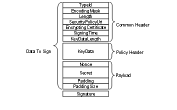
Figure 39 – EncryptedSecret layout
The TypeId specifies how the EncryptedSecret is serialized and secured. For example, the RsaEncryptedSecret requires that the KeyData be encrypted with the public key associated with the EncryptingCertificate before it is serialized.
The SecurityPolicyUri is used to determine what algorithms were used to encrypt and sign the data. Valid SecurityPolicyUris are defined in OPC 10000-7.
The payload is always encrypted using the symmetric encryption algorithm specified by the SecurityPolicyUri. The KeyData provides the keys needed for symmetric encryption. The structure of the KeyData depends on the EncryptedSecret DataType.
The EncryptedSecret is secured and serialized as follows:
· Serialize the common header;
· Serialize the KeyData;
· If required, encrypt the KeyData and append the result to the common header;
· Update the KeyDataLength with the length of the encrypted KeyData;
· Append the Nonce and the Secret to the encrypted KeyData;
· Calculate padding required on the payload and append after the Secret;
· Encrypt the payload;
· Calculate a Signature;
· Append the Signature.
Individual fields are serialized using the UA Binary encoding (see OPC 10000-6) for the DataType specified in Table 187. The Padding is used to ensure there is enough data to fill an integer multiple of encryption blocks. The size of the encryption block depends on the encryption algorithm. The total length of the Padding, not including the PaddingSize, is encoded as a UInt16. The individual bytes of the Padding are set to the least significant byte of the PaddingSize.
The EncryptedSecret is deserilized and validated as follows:
· Deserialize the common header;
· Verify the Signature if the KeyData is not encrypted;
· Decrypt the KeyData and verify the Signature if the KeyData is encrypted;
· Decrypt the payload;
· Verify the padding on the payload;
· Extract the Secret;
The fields in the EncryptedSecret are described in Table 187. The first three fields TypeId, EncodingMask and Length belong to the ExtensionObject encoding defined in OPC 10000-6.
Table 187 – EncryptedSecret layout
|
Name |
Type |
Description |
|
TypeId |
NodeId |
The NodeId of the DataType Node. |
|
EncodingMask |
Byte |
This value is always 1. |
|
Length |
Int32 |
The length of the data that follows including the Signature. |
|
SecurityPolicyUri |
String |
The URI for the SecurityPolicy used to apply security. |
|
Certificate |
ByteString |
The signing and/or encrypting Certificate. |
|
SigningTime |
DateTime |
When the Signature was created. |
|
KeyDataLength |
UInt16 |
The length, in bytes, of the KeyData that follows If the KeyData is encrypted this is the length of the encrypted data; Otherwise, it is the length of the unencrypted data. |
|
KeyData |
Byte [*] |
The key data used to create the keys needed for decrypting and verifying the payload using the SymmetricEncryptionAlgorithm specified by the SecurityPolicyUri. Each EncryptedSecret DataType describes how the key data is structured for different SecurityPolicies. |
|
Nonce |
ByteString |
This is the last serverNonce returned in the CreateSession or ActivateSession Response when a UserIdentityToken is passed with the ActivateSession Request. If used outside of an ActivateSession call, the Nonce is created by the sender and its length shall be between 32 and 128 bytes inclusive. |
|
Secret |
ByteString |
The secret to protect. The password when used with UserNameIdentityTokens. The tokenData when used with IssuedIdentityTokens. If the Secret is a String is it encoded using UTF-8 first. |
|
PayloadPadding |
Byte[*] |
Additional padding added to ensure the size of the encrypted payload is an integer multiple of the InitializationVectorLength specified by the SecurityPolicyUri. If the InitializationVectorLength is less than 16 bytes then 16 bytes are used instead. The value of each byte is the least significant byte of the PayloadPaddingSize. |
|
PayloadPaddingSize |
UInt16 |
The size of the padding added to the payload. |
|
Signature |
Byte[*] |
The Signature calculated after all encryption is applied. Each EncryptedSecret DataType describes how the Signature is calculated for different SecurityPolicies. |
The PayloadPaddingSize adjusted with the following formula:
If (Secret.Length + PayloadPaddingSize < InitializationVectorLength) Then
PayloadPaddingSize = PayloadPaddingSize + InitializationVectorLength
Where the InitializationVectorLength is specified by the SymmetricEncryptionAlgorithm.
The currently available EncryptedSecret DataTypes are defined in Table 188.
Table 188 – EncryptedSecret DataTypes
|
Type Name |
When to Use |
|
RsaEncryptedSecret |
Used when the SecurityPolicy
requires the use of RSA cryptography. |
|
EccEncryptedSecret |
Used when the SecurityPolicy
requires the use of ECC cryptography. |
The RsaEncryptedSecret uses RSA based Asymmetric Cryptography.
Additional semantics for the fields in the EncryptedSecret layout for the RsaEncryptedSecret Structure are described in Table 189.
Table 189 – RsaEncryptedSecret structure
|
Name |
Type |
Description |
|
TypeId |
NodeId |
The NodeId of the RsaEncryptedSecret DataType Node. |
|
EncodingMask |
Byte |
See Table 187. |
|
Length |
UInt32 |
See Table 187. |
|
SecurityPolicyUri |
String |
See Table 187. |
|
Certificate |
ByteString |
The SHA1 hash of the DER form of the Certificate used to encrypt the KeyData. |
|
SigningTime |
DateTime |
See Table 187. |
|
KeyDataLength |
UInt16 |
The length, in bytes, of the encrypted KeyData. |
|
KeyData |
|
The KeyData is encrypted with the PublicKey associated with the receiver of the EncryptedSecret. The creator of the EncryptedSecret generates the SigningKey, EncryptingKey and InitializationVector using a cryptographic random number generator with the lengths required by the SecurityPolicy. |
|
SigningKey |
ByteString |
The key used to compute the Signature. |
|
EncryptingKey |
ByteString |
The key used to encrypt payload. |
|
InitializationVector |
ByteString |
The initialization vector used with the EncryptingKey. |
|
Nonce |
ByteString |
A Nonce. This is the last ServerNonce returned in the CreateSession or ActivateSession Response when proving a UserIdentityToken passed in the ActivateSession Request. In other contexts, this is a Nonce created by the sender with a length between 32 and 128 bytes inclusive. |
|
Secret |
ByteString |
See Table 187. |
|
PayloadPadding |
Byte[*] |
See Table 187. |
|
PayloadPaddingSize |
UInt16 |
See Table 187. |
|
Signature |
Byte[*] |
The Signature calculated with the SigningKey using the SymmetricEncryptionAlgorithm from the SecurityPolicy. The Signature is calculated after encrypting the KeyData and the payload. The Signature can only be checked after the KeyData is decrypted. It allows the receiver to verify that the message has not beem tampered with. It does not provide any information about who created the EncryptedSecret. |
The EccEncryptedSecret uses ECC based Asymmetric Cryptography.
Additional semantics for the fields in the EncryptedSecret layout for the EccEncryptedSecret Structure are described in Table 190.
The EccEncryptedSecret uses ECC EphemeralKeys to create the symmetric key used to encrypt the Secret. The handshake required to create and use the EphemeralKeys is described in OPC 10000-6.
Table 190 – EccEncryptedSecret Layout
|
Name |
Type |
Description |
|
TypeId |
NodeId |
The NodeId of the EccEncryptedSecret DataType Node. |
|
EncodingMask |
Byte |
See Table 187 |
|
Length |
UInt32 |
See Table 187 |
|
SecurityPolicyUri |
String |
See Table 187 |
|
Certificate |
ByteString |
The signing Certificate encoded in DER form. The value shall include the entire chain. This value may be null or empty if the SigningCertificate is known to the receiver. This is true if the structure is used to provide a UserIdentityToken to a Server over a SecureChannel and the SigningCertificate is the Client ApplicationInstance Certificate. |
|
SigningTime |
DateTime |
See Table 187 |
|
KeyDataLength |
UInt16 |
The length of the KeyData without encryption. |
|
KeyData |
|
The KeyData is not encrypted. |
|
SenderPublicKey |
ByteString |
The Public Key for the EphemeralKey created by the sender. |
|
ReceiverPublicKey |
ByteString |
The Public Key for the EphemeralKey created by the receiver. |
|
Nonce |
ByteString |
A Nonce. This is the last ServerNonce returned in the CreateSession or ActivateSession Response when proving a UserIdentityToken passed in the ActivateSession Request. In other contexts, this is a Nonce created by the sender with a length between 32 and 128 bytes inclusive. |
|
Secret |
ByteString |
See Table 187 |
|
PayloadPadding |
Byte [*] |
See Table 187 |
|
PayloadPaddingSize |
UInt16 |
See Table 187 |
|
Signature |
Byte [*] |
When using AuthenticatedEncryption the Signature has two parts: the Signature produced when the secret is encrypted using the SymmetricEncryptionAlgorithm and the Signature calculated using the Certificate and the AsymmetricSignatureAlgorithm. Both Signatures are calculated from the start of the packet. The AsymmetricSignatureAlgorithm Signature includes the SymmetricEncryptionAlgorithm Signature. When using UnauthenticatedEncryption the Signature is only calculated using the Certificate and the AsymmetricSignatureAlgorithm. |
The AnonymousIdentityToken is used to indicate that the Client has no user credentials.
Table 191 defines the AnonymousIdentityToken parameter.
Table 191 – AnonymousIdentityToken
|
Name |
Type |
Description |
|
AnonymousIdentityToken |
Structure |
An anonymous user identity. |
|
policyId |
String |
An identifier for the UserTokenPolicy that the token conforms to. The UserTokenPolicy structure is defined in 7.42. Servers that provide a null or empty PolicyId shall accept null or empty and treat them as equal. |
The UserNameIdentityToken is used to pass simple username/password credentials to the Server.
This token shall be encrypted by the Client if required by the SecurityPolicy of the UserTokenPolicy. The Server should specify a SecurityPolicy for the UserTokenPolicy if the SecureChannel has a SecurityPolicy of None and no transport layer encryption is available. If None is specified for the UserTokenPolicy and SecurityPolicy is None then the password only contains the UTF-8 encoded password. The SecurityPolicy of the SecureChannel is used if no SecurityPolicy is specified in the UserTokenPolicy. The Server shall specify a SecurityPolicy for the UserTokenPolicy if the SecureChannel has a SecurityPolicy other than None and the MessageSecurityMode is not SIGNANDENCRYPT. See Table 193 for possible combinations.
If the token is to be encrypted the password shall be converted to a UTF-8 ByteString, encrypted and then serialized according to the following rules. When using an RSA based SecurityPolicy and the password exceeds 64 bytes, it is encrypted and serialized as described in 7.41.2.4. For passwords that do not exceed 64 bytes, it is encrypted and serialized as described in 7.41.2.2. When using the ECC based SecurityPolicies the password is encrypted and serialized as described in 7.41.2.5.
The Server shall decrypt the password and verify the ServerNonce.
If the SecurityPolicy is None then the password only contains the UTF-8 encoded password. This configuration should not be used unless the network traffic is encrypted in some other manner such as a VPN. The use of this configuration without network encryption would result in a serious security fault, in that it would cause the appearance of a secure user access, but it would make the password visible in clear text.
Table 192 defines the UserNameIdentityToken parameter.
Table 192 – UserNameIdentityToken
|
Name |
Type |
Description |
|
UserNameIdentityToken |
Structure |
UserName value. |
|
policyId |
String |
An identifier for the UserTokenPolicy that the token conforms to. The UserTokenPolicy structure is defined in 7.42. Servers that provide a null or empty PolicyId shall accept null or empty and treat them as equal. |
|
userName |
String |
A string that identifies the user. |
|
password |
ByteString |
The password for the user. The password can be an empty string. The format used for the encrypted data is described in 7.41.2.2. |
|
encryptionAlgorithm |
String |
A string containing the URI of the AsymmetricEncryptionAlgorithm. The URI string values are defined names that may be used as part of the security profiles specified in OPC 10000-7. This parameter is null or empty if the password is not encrypted. |
Table 193 describes the dependencies for selecting the AsymmetricEncryptionAlgorithm for the UserNameIdentityToken. The SecureChannel SecurityPolicy URI is specified in the EndpointDescription and used in subsequent OpenSecureChannel requests. The UserTokenPolicy SecurityPolicy URI is specified in the EndpointDescription. The encryptionAlgorithm is specified in the UserNameIdentityToken or IssuedIdentityToken provided by the Client in the ActivateSession call. The SecurityPolicy Other in the table refers to any SecurityPolicy other than None. The selection of the EncryptionAlgorithm is based on the UserTokenPolicy. The SecureChannel SecurityPolicy is used if the UserTokenPolicy is null or empty.
Table 193 – EncryptionAlgorithm selection
|
SecureChannel SecurityPolicy |
SecureChannel SecurityMode |
UserTokenPolicy SecurityPolicy |
UserIdentityToken EncryptionAlgorithm |
|
Security Policy - None |
NONE |
Null or empty |
No encryption (a) |
|
Security Policy - None |
NONE |
Security Policy - None |
No encryption (a) |
|
Security Policy - None |
NONE |
Security Policy - Other |
Asymmetric algorithm for "Other" |
|
Security Policy - Other |
Other than NONE |
Null or empty |
Asymmetric algorithm for "Other" |
|
Security Policy - Other |
Other than NONE |
Security Policy - Yet another |
Asymmetric algorithm for "Yet another" |
|
Security Policy - Other |
Other than NONE |
Security Policy - Other |
Asymmetric algorithm for "Other" |
|
Security Policy - Other |
SIGNANDENCRYPT |
Security Policy - None |
No encryption but encrypted SecureChannel |
|
Security Policy - Other |
SIGN |
Security Policy - None |
Invalid configuration shall be rejected. |
|
(a) The use of this configuration without network encryption would result in a serious security fault. |
|||
The X509IdentityToken is used to pass an X.509 v3 Certificate which is issued by the user.
This token shall always be accompanied by a Signature in the userTokenSignature parameter of ActivateSession if required by the SecurityPolicy. The Server should specify a SecurityPolicy for the UserTokenPolicy if the SecureChannel has a SecurityPolicy of None.
Table 194 defines the X509IdentityToken parameter.
Table 194 – X.509 v3 Identity Token
|
Name |
Type |
Description |
|
X509IdentityToken |
structure |
X.509 v3 value. |
|
policyId |
String |
An identifier for the UserTokenPolicy that the token conforms to. The UserTokenPolicy structure is defined in 7.42. Servers that provide a null or empty PolicyId shall accept null or empty and treat them as equal. |
|
certificateData |
ByteString |
The X.509 v3 Certificate in DER format. |
The IssuedIdentityToken is used to pass SecurityTokens issued by an external Authorization Service to the Server. These tokens may be text or binary.
OAuth2 defines a standard for Authorization Services that produce JSON Web Tokens (JWT). These JWTs are passed as an Issued Token to an OPC UA Server which uses the signature contained in the JWT to validate the token. OPC 10000-6 describes OAuth2 and JWTs in more detail. If the token is encrypted, it shall use the EncryptedSecret format defined in 7.41.2.3.
This token shall be encrypted by the Client if required by the SecurityPolicy of the UserTokenPolicy. The Server should specify a SecurityPolicy for the UserTokenPolicy if the SecureChannel has a SecurityPolicy of None and no transport layer encryption is available. The SecurityPolicy of the SecureChannel is used If no SecurityPolicy is specified in the UserTokenPolicy.
If the SecurityPolicy is not None, the tokenData shall be encoded in UTF-8 (if it is not already binary), signed and encrypted according the rules specified for the tokenType of the associated UserTokenPolicy (see 7.42).
If the SecurityPolicy is None then the tokenData only contains the UTF-8 encoded tokenData. This configuration should not be used unless the network is encrypted in some other manner such as a VPN. The use of this configuration without network encryption would result in a serious security fault, in that it would cause the appearance of a secure user access, but it would make the token visible in clear text.
IssuedIdentityTokens have an expiration time, and a Server shall invalidate the credentials of the Session within a configurable time after the token expires. The Session shall stay valid with the Anonymous Role. Clients should renew the token with ActivateSession before the expiration time to avoid communication interruption.
Table 195 defines the IssuedIdentityToken parameter.
Table 195 – IssuedIdentityToken
|
Name |
Type |
Description |
|
IssuedIdentityToken |
structure |
The token provided by an Authorization Service. |
|
policyId |
String |
An identifier for the UserTokenPolicy that the token conforms to. The UserTokenPolicy structure is defined in 7.42. Servers that provide a null or empty PolicyId shall accept null or empty and treat them as equal. |
|
tokenData |
ByteString |
The text or binary representation of the token. The format of the data depends on the associated UserTokenPolicy. |
|
encryptionAlgorithm |
String |
The URI of the AsymmetricEncryptionAlgorithm. The list of OPC UA-defined names that may be used is specified in OPC 10000-7. See Table 193 for details on picking the correct URI. This parameter is null or empty if the tokenData is not encrypted or if the EncryptedSecret format is used. |
The components of this parameter are defined in Table 196.
Table 196 – UserTokenPolicy
|
Name |
Type |
Description |
|
UserTokenPolicy |
structure |
Specifies a UserIdentityToken that a Server will accept. |
|
policyId |
String |
An identifier for the UserTokenPolicy assigned by the Server. The identifier may be null or empty. Null or empty are equal. The identifier shall be unique across the UserTokenPolicies assigned by the Server. The Client specifies this value when it constructs a UserIdentityToken that conforms to the policy. This value is only unique within the context of a single Server. |
|
tokenType |
Enum User TokenType |
The type of user identity token required. The UserTokenType is defined in 7.43 A tokenType of ANONYMOUS indicates that the Server does not require any user identification. In this case, the Client Application Instance Certificate is used as the user identification. |
|
issuedTokenType |
String |
A URI for the type of token. OPC 10000-6 defines URIs for common issued token types. Vendors may specify their own token types. This field may only be specified if TokenType is ISSUEDTOKEN. |
|
issuerEndpointUrl |
String |
An optional string which depends on the Authorization Service. The meaning of this value depends on the issuedTokenType. Further details for the different token types are defined in OPC 10000-6. For JWTs this is a JSON object with fields defined in OPC 10000-6. |
|
securityPolicyUri |
String |
The security policy to use when encrypting or signing the UserIdentityToken when it is passed to the Server in the ActivateSession request. Clause 7.41 describes how this parameter is used. The security policy for the SecureChannel is used if this value is null or empty. |
The UserTokenType is an enumeration that specifies the user identity token type. The possible values are described in Table 197.
Table 197 – UserTokenType values
|
Name |
Value |
Description |
|
ANONYMOUS |
0 |
No token is required. |
|
USERNAME |
1 |
A username/password token. |
|
CERTIFICATE |
2 |
An X.509 v3 Certificate token. |
|
ISSUEDTOKEN |
3 |
Any token issued by an Authorization Service. |
This primitive data type is a UInt32 that represents the time in seconds since the year 2000. The epoch date is midnight UTC (00:00) on January 1, 2000.
It is used as version number based on the last change time. If the version is updated, the new value shall be greater than the previous value.
If a Variable is initialized with a VersionTime value, the value shall be either loaded from persisted configuration or time synchronization shall be available to ensure a unique version is applied.
The value 0 is used to indicate that no version information is available.
The components of this parameter are defined in Table 198.
Table 198 – ViewDescription
|
Name |
Type |
Description |
|
ViewDescription |
structure |
Specifies a View. |
|
viewId |
NodeId |
NodeId of the View to Query. A null value indicates the entire AddressSpace. |
|
timestamp
|
UtcTime |
The time date desired. The corresponding version is the one with the closest previous creation timestamp. Either the Timestamp or the viewVersion parameter may be set by a Client, but not both. If ViewVersion is set this parameter shall be null. |
|
viewVersion |
UInt32 |
The version number for the View desired. When Nodes are added to or removed from a View, the value of a View’s ViewVersion Property is updated. Either the Timestamp or the viewVersion parameter may be set by a Client, but not both. The ViewVersion Property is defined in OPC 10000-3. If timestamp is set this parameter shall be 0. The current view is used if timestamp is null and viewVersion is 0. |
Annex A
(informative)
BNF definitions
The BNF (Backus-Naur form) used in this annex uses `<´ and `>´ to mark symbols, `[´ and `]´ to identify optional paths and `|´ to identify alternatives. If the ‘(‘ and ‘)’ symbols are used, it indicates sets.
A RelativePath is a structure that describes a sequence of References and Nodes to follow. This annex describes a text format for a RelativePath that can be used in documentation or in files used to store configuration information.
The components of a RelativePath text format are specified in Table A.1.
Table A.1 – RelativePath
|
Symbol |
Meaning |
|
/ |
The forward slash character indicates that the Server is to follow any subtype of HierarchicalReferences. |
|
. |
The period (dot) character indicates that the Server is to follow any subtype of a Aggregates ReferenceType. |
|
<[#!ns:]ReferenceType> |
A string delimited by the ‘<’ and ‘>’ symbols specifies the BrowseName of a ReferenceType to follow. By default, any References of the subtypes the ReferenceType are followed as well. A ‘#’ placed in front of the BrowseName indicates that subtypes should not be followed. A ‘!’ in front of the BrowseName is used to indicate that the inverse Reference should be followed. The BrowseName may be qualified with a namespace index (indicated by a numeric prefix followed by a colon). This namespace index is used specify the namespace component of the BrowseName for the ReferenceType. If the namespace prefix is omitted then namespace index 0 is used. |
|
[ns:]BrowseName |
A string that follows a ‘/’, ‘.’ or ‘>’ symbol specifies the BrowseName of a target Node to return or follow. This BrowseName may be prefixed by its namespace index. If the namespace prefix is omitted then namespace index 0 is used. Omitting the final BrowseName from a path is equivalent to a wildcard operation that matches all Nodes which are the target of the Reference specified by the path. |
|
& |
The & sign character is the escape character. It is used to specify reserved characters that appear within a BrowseName. A reserved character is escaped by inserting the ‘&’ in front of it. Examples of BrowseNames with escaped characters are: Received browse path name Resolves to “&/Name_1” “/Name_1” “&.Name_2” “.Name_2” “&:Name_3” “:Name_3” “&&Name_4” “&Name_4” |
Table A.2 provides RelativePaths examples in text format.
Table A.2 – RelativePath Examples
|
Browse Path |
Description |
|
“/2:Block&.Output” |
Follows any forward hierarchical Reference with target BrowseName = “2:Block.Output”. |
|
“/3:Truck.0:NodeVersion” |
Follows any forward hierarchical Reference with target BrowseName = “3:Truck” and from there a forward Aggregates Reference to a target with BrowseName “0:NodeVersion”. |
|
“<1:ConnectedTo>1:Boiler/1:HeatSensor” |
Follows any forward Reference with a BrowseName = ‘1:ConnectedTo’ and finds targets with BrowseName = ‘1:Boiler’. From there follows any hierarchical Reference and find targets with BrowseName = ‘1:HeatSensor’. |
|
“<1:ConnectedTo>1:Boiler/” |
Follows any forward Reference with a BrowseName = ‘1:ConnectedTo’ and finds targets with BrowseName = ‘1:Boiler’. From there it finds all targets of hierarchical References. |
|
“<0:HasChild>2:Wheel” |
Follows any forward Reference with a BrowseName = ‘HasChild’ and qualified with the default OPC UA namespace. Then find targets with BrowseName = ‘Wheel’ qualified with namespace index ‘2’. |
|
“<!HasChild>Truck” |
Follows any inverse Reference with a BrowseName = ‘HasChild’. Then find targets with BrowseName = ‘Truck’. In both cases, the namespace component of the BrowseName is assumed to be 0. |
|
“<0:HasChild>” |
Finds all targets of forward References with a BrowseName = ‘HasChild’ and qualified with the default OPC UA namespace. |
The following BNF describes the syntax of the RelativePath text format.
<relative-path> ::= <reference-type> <browse-name> [relative-path]
<reference-type> ::= '/' | '.' | '<' ['#'] ['!'] <browse-name> '>'
<browse-name> ::= [<namespace-index> ':'] <name>
<namespace-index> ::= <digit> [<digit>]
<digit> ::= '0' | '1' | '2' | '3' | '4' | '5' | '6' | '7' | '8' | '9'
<name> ::= (<name-char> | '&' <reserved-char>) [<name>]
<reserved-char> ::= '/' | '.' | '<' | '>' | ':' | '#' | '!' | '&'
<name-char> ::= All valid characters for a String (see OPC 10000-3) excluding reserved-chars.
The following BNF describes the syntax of the NumericRange parameter type.
<numeric-range> ::= <dimension> | <dimension> ',' <numeric-range>
<dimension> ::= <index> | <index> ':' <dimension>
<index> ::= <digit> | <digit> <index>
<digit> ::= '0' | '1' | '2' | '3' | '4' | '5' | '6' | '7' | '8' | '9'
Annex B
(informative)
ContentFilter and Query examples
B.1 Simple ContentFilter examples
These examples provide fairly simple ContentFilters. Filter similar to these examples may be used in processing events.
The following conventions apply to these examples with regard to how Attribute operands are used (for a definition of this operand see 7.7.4):
· AttributeOperand: Refers to a Node, an Attribute of a Node or the Value Attribute of a Property associated with a Node. In the examples, the character names of NodeIds are used instead of an actual nodeId, this also applies to Attribute Ids.
· The string representation of relative paths is used instead of the actual structure.
· The NamespaceIndex used in all examples is 12 (it could just as easily have been 4 or 23 or any value). For more information about NamespaceIndex, see OPC 10000-3. The use of the NamespaceIndex illustrates that the information model being used in the examples is not a model defined by this document, but one created for the examples.
For example the logic describe by ‘(((AType.A = 5) or InList(BType.B, 3,5,7)) and BaseObjectType.displayName LIKE “Main%”)’ would result in a logic tree as shown in Figure B.1 and a ContentFilter as shown in Table B.1. For this example to return anything AType and BType both shall be subtypes of BaseObjectType, or the resulting “And” operation would always be false.
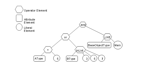
Figure B.1 – Filter logic tree example
Table B.1 describes the elements, operators and operands used in the example.
Table B.1 – ContentFilter example
|
Element[] |
Operator |
Operand[0] |
Operand[1] |
Operand[2] |
Operand[3] |
|
0 |
And |
ElementOperand = 1 |
Element Operand = 4 |
|
|
|
1 |
Or |
ElementOperand = 2 |
Element Operand = 3 |
|
|
|
2 |
Equals |
AttributeOperand = NodeId: AType, BrowsePath: “.12:A”, Attribute:value |
LiteralOperand = ‘5’ |
|
|
|
3 |
InList |
AttributeOperand = NodeId: BType, BrowsePath: “.12:B”, Attribute:value |
LiteralOperand = ‘3’ |
LiteralOperand = ‘5’ |
LiteralOperand = ‘7’ |
|
4 |
Like |
AttributeOperand = NodeId: BaseObjectType, BrowsePath: “.”, Attribute: displayName |
LiteralOperand = “Main%” |
|
|
As another example a filter to select all SystemEvents (including derived types) that are contained in the Area1 View or the Area2 View would result in a logic tree as shown in Figure B.2 and a ContentFilter as shown in Table B.2.
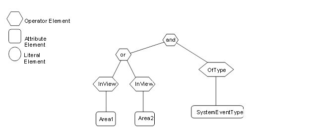
Figure B.2 – Filter logic tree example
Table B.2 describes the elements, operators and operands used in the example.
Table B.2 – ContentFilter example
|
Element[] |
Operator |
Operand[0] |
Operand[1] |
|
0 |
And |
ElementOperand = 1 |
ElementOperand = 4 |
|
1 |
Or |
ElementOperand = 2 |
ElementOperand = 3 |
|
2 |
InView |
AttributeOperand = NodeId: Area1, BrowsePath: ".", Attribute: NodeId |
|
|
3 |
InView |
AttributeOperand = NodeId: Area2, BrowsePath: ".", Attribute: NodeId |
|
|
4 |
OfType |
AttributeOperand = NodeId: SystemEventType, BrowsePath: ".", Attribute: NodeId” |
|
B.2 Complex Examples of Query Filters
These query examples illustrate complex filters. The following conventions apply to these examples with regard to Attribute operands (for a definition of these operands, see 7.7.4).
· AttributeOperand: Refers to a Node, an Attribute of a Node or the Value Attribute of a Property associated with a Node. In the examples character names of ExpandedNodeId are used instead of an actual ExpandedNodeId, this also applies to Attribute Ids.
· The string representation of relative paths is used instead of the actual structure.
· The NamespaceIndex used in all examples is 12 (it could just as easily have been 4 or 23 or any value). For more information about NamespaceIndex, see OPC 10000-3. The use of the NamespaceIndex illustrates that the information model being used in the examples is not a model defined by this document, but one created for the examples.
The following examples use the type model described below. All Property values are assumed to be string unless otherwise noted
New Reference types:
"HasChild" derived from HierarchicalReference.
"HasAnimal" derived from HierarchicalReference.
"HasPet" derived from HasAnimal.
"HasFarmAnimal" derived from HasAnimal.
"HasSchedule" derived from HierarchicalReference.
PersonType derived from BaseObjectType adds:
HasProperty "LastName".
HasProperty "FirstName".
HasProperty "StreetAddress".
HasProperty "City".
HasProperty "ZipCode".
May have HasChild reference to a node of type PersonType.
May have HasAnimal reference to a node of type AnimalType (or a subtype of this Reference type).
AnimalType derived from BaseObjectType adds:
May have HasSchedule reference to a node of type FeedingScheduleType.
HasProperty "Name".
DogType derived from AnimalType adds:
HasProperty "NickName".
HasProperty "DogBreed".
HasProperty "License".
CatType derived from AnimalType adds:
HasProperty "NickName".
HasProperty "CatBreed".
PigType derived from AnimalType adds:
HasProperty "PigBreed".
ScheduleType derived from BaseObjectType adds:
HasProperty "Period".
FeedingScheduleType derived from ScheduleType adds:
HasProperty "Food".
HasProperty "Amount" (Stored as an Int32).
AreaType derived from BaseObjectType is just a simple Folder and contains no Properties.
This example type system is shown in Figure B.3. In this Figure, the OPC UA notation is used for all References to ObjectTypes, Variables, Properties and subtypes. Additionally, supported References are contained in an inner box. The actual references only exist in the instances, thus, no connections to other Objects are shown in the Figure and they are subtypes of the listed Reference.
Figure B.3 – Example Type Nodes
A corresponding example set of instances is shown in Figure B.4. These instances include a type Reference for Objects. Properties also have type References, but the References are omitted for simplicity. The name of the Object is provided in the box and a numeric instance NodeId in brackets. Standard ReferenceTypes use the OPC UA notation, custom ReferenceTypes are listed as a named Reference. For Properties, the BrowseName, NodeId, and Value are shown. The Nodes that are included in a View (View1) are enclosed in the coloured box. Two Area nodes are included for grouping of the existing person nodes. All custom nodes are defined in namespace 12 which is not included in Figure B.4.
Figure B.4 – Example Instance Nodes
For all of the examples in 7.7.4, the type definition Node is listed in its symbolic form, in the actual call it would be the ExpandedNodeId assigned to the Node. The Attribute is the symbolic name of the Attribute, in the actual call they would be translated to the IntegerId of the Attribute. Also in all of the examples the BrowseName is included in the result table for clarity; normally this would not be returned.
All of the examples include the following items:
· an English description of the object of the query;
· an SQL like description of the query;
· a table that has a NodeTypeDescription of the items that are to be returned;
· a figure illustrating the query filter;
· a table describing the content filter;
· a table describing the resulting dataset.
The examples assume namespace 12 is the namespace for all of the custom definitions described for the examples.
This example requests a simple layered filter, a person has a pet and the pet has a schedule.
Example 1: Get PersonType.LastName, AnimalType.Name, ScheduleType.Period where the Person Has a Pet and that Pet Has a Schedule.
The NodeTypeDescription parameters used in the example are described in Table B.3.
Table B.3 – Example 1 NodeTypeDescription
|
Type Definition Node |
Include Subtypes |
QueryDataDescription |
||
|
Relative Path |
Attribute |
Index Range |
||
|
FALSE |
“.12:LastName” |
value |
N/A |
|
|
“<12:HasPet>12:AnimalType. 12:Name” |
value |
N/A |
||
|
“<12:HasPet>12:AnimalType<12:HasSchedule> 12:Schedule. 12:Period” |
value |
N/A |
||
The corresponding ContentFilter is illustrated in Figure B.5.
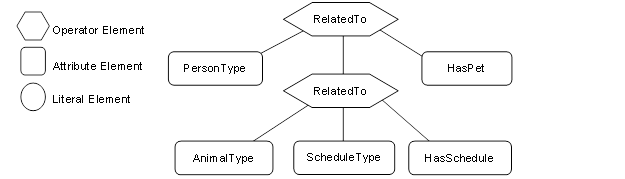
Figure B.5 – Example 1 Filter
Table B.4 describes the ContentFilter elements, operators and operands used in the example.
Table B.4 – Example 1 ContentFilter
|
Element[] |
Operator |
Operand[0] |
Operand[1] |
Operand[2] |
Operand[3] |
|
1 |
RelatedTo |
AttributeOperand = NodeId: PersonType, BrowsePath “.”, Attribute: NodeId |
ElementOperand = 2 |
AttributeOperand = NodeId: HasPet, BrowsePath “.”, Attribute: NodeId |
LiteralOperand = ‘1’ |
|
2 |
RelatedTo |
AttributeOperand = NodeId: AnimalType, BrowsePath “.”, Attribute: NodeId |
AttributeOperand = NodeId: ScheduleType, BrowsePath “.”, Attribute: NodeId |
AttributeOperand = NodeId: HasSchedule, BrowsePath “.”, Attribute: NodeId |
LiteralOperand= ‘1’ |
Table B.5 describes the QueryDataSet that results from this query if it were executed against the instances described in Figure B.4
Table B.5 – Example 1 QueryDataSets
|
NodeId |
TypeDefinition NodeId |
RelativePath |
Value |
|
12:30 (JFamily1) |
PersonType |
“.12:LastName” |
Jones |
|
“<12:HasPet>12:AnimalType. 12:Name” |
Rosemary |
||
|
Basil |
|||
|
“<12:HasPet>12:AnimalType<12:HasSchedule> 12:Schedule.12:Period” |
Hourly |
||
|
Daily |
|||
|
12:42(HFamily1) |
PersonType |
“.12:LastName” |
Hervey |
|
“<12:HasPet>12:AnimalType. 12:Name” |
Oliver |
||
|
“<12:HasPet>12:AnimalType<12:HasSchedule> 12:Schedule.12:Period” |
Daily |
NOTE The RelativePath column and browse name (in parentheses in the NodeId column) are not in the QueryDataSet and are only shown here for clarity. The TypeDefinition NodeId would be an integer not the symbolic name that is included in the table.
The Value column is returned as an array for each Node description, where the order of the items in the array would correspond to the order of the items that were requested for the given Node Type. In Addition, if a single Attribute has multiple values then it would be returned as an array within the larger array, for example in this table Rosemary and Basil would be returned in a array for the .<HasPet>.AnimalType.Name item. They are show as separate rows for ease of viewing. The actual value array for JFamily1 would be (“Jones”, {“RoseMary”, ”Basil”}, {“Hourly”, “Daily”})
The second example illustrates receiving a list of disjoint Nodes and also illustrates that an array of results can be received.
Example 2: Get PersonType.LastName, AnimalType.Name where a person has a child or (a pet is of type cat and has a feeding schedule).
The NodeTypeDescription parameters used in the example are described in Table B.6.
Table B.6 – Example 2 NodeTypeDescription
|
Type Definition Node |
Include Subtypes |
QueryDataDescription |
||
|
Relative Path |
Attribute |
Index Range |
||
|
PersonType |
FALSE |
“.12:LastName” |
Value |
N/A |
|
AnimalType |
TRUE |
“.12:Name” |
Value |
N/A |
The corresponding ContentFilter is illustrated in
Figure B.6.
Figure B.6 – Example 2 filter logic tree
Table B.7 describes the elements, operators and operands used in the example. It is worth noting that a CatType is a subtype of AnimalType.
Table B.7 – Example 2 ContentFilter
|
Element[] |
Operator |
Operand[0] |
Operand[1] |
Operand[2] |
Operand[3] |
|
0 |
Or |
ElementOperand=1 |
ElementOperand = 2 |
|
|
|
1 |
RelatedTo |
AttributeOperand = NodeId: PersonType, BrowsePath “.”, Attribute: NodeId |
AttributeOperand = NodeId: PersonType, BrowsePath “.”, Attribute: NodeId |
AttributeOperand = NodeId: HasChild, BrowsePath “.”, Attribute: NodeId |
LiteralOperand = ‘1’ |
|
2 |
RelatedTo |
AttributeOperand = NodeId: CatType, BrowsePath “.”, Attribute: NodeId |
AttributeOperand = NodeId: FeedingScheduleType, BrowsePath “.”, Attribute: NodeId |
AttributeOperand = NodeId: HasSchedule, BrowsePath “.”, Attribute: NodeId |
LiteralOperand = ‘1’ |
The results from this query would contain the QueryDataSets shown in Table B.8.
Table B.8 – Example 2 QueryDataSets
|
NodeId |
TypeDefinition NodeId |
RelativePath |
Value |
|
12:30 (Jfamily1) |
PersonType |
. 12:LastName |
Jones |
|
12:42 (HFamily1) |
PersonType |
. 12:LastName |
Hervey |
|
12:48 (HFamily2) |
PersonType |
. 12:LastName |
Hervey |
|
12:70 (Cat1) |
CatType |
. 12:Name |
Rosemary |
|
12:74 (Cat2) |
CatType |
. 12:Name |
Basil |
NOTE The relative path column and browse name (in parentheses in the NodeId column) are not in the QueryDataSet and are only shown here for clarity. The TypeDefinition NodeId would be a NodeId not the symbolic name that is included in the table.
The third example provides a more complex Query in which the results are filtered on multiple criteria.
Example 3: Get PersonType.LastName, AnimalType.Name, ScheduleType.Period where a person has a pet and the animal has a feeding schedule and the person has a Zipcode = ‘02138’ and (the Schedule.Period is Daily or Hourly) and Amount to feed is > 10.
Table B.9 describes the NodeTypeDescription parameters used in the example.
Table B.9 – Example 3 - NodeTypeDescription
|
Type Definition Node |
Include Subtypes |
QueryDataDescription |
||
|
RelativePath |
Attribute |
Index Range |
||
|
PersonType |
FALSE |
“12:LastName” |
Value |
N/A |
|
|
|
“<12:HasPet>12:AnimalType. 12:Name” |
Value |
N/A |
|
|
|
“<12:HasPet>12:AnimalType<12:HasSchedule> 12:FeedingSchedule.Period” |
Value |
N/A |
The corresponding ContentFilter is illustrated in Figure B.7.
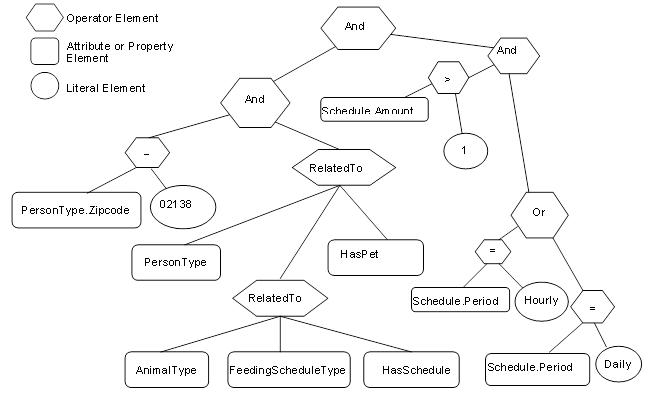
Figure B.7 – Example 3 filter logic tree
Table B.10 describes the elements, operators and operands used in the example.
Table B.10 – Example 3 ContentFilter
|
Element[] |
Operator |
Operand[0] |
Operand[1] |
Operand[2] |
Operand[3] |
|
0 |
And |
Element Operand= 1 |
ElementOperand = 2 |
|
|
|
1 |
And |
ElementOperand = 4 |
ElementOperand = 6 |
|
|
|
2 |
And |
ElementOperand = 3 |
ElementOperand = 9 |
|
|
|
3 |
Or |
ElementOperand = 7 |
ElementOperand = 8 |
|
|
|
4 |
RelatedTo |
AttributeOperand = NodeId: 12:PersonType, BrowsePath “.”, Attribute: NodeId |
ElementOperand = 5 |
AttributeOperand = NodeId: 12:HasPet, BrowsePath “.”, Attribute: NodeId |
LiteralOperand = ‘1’ |
|
5 |
RelatedTo |
AttributeOperand = Node: 12:AnilmalType, BrowsePath “.”, Attribute: NodeId Alias: AT |
AttributeOperand = NodeId: 12:FeedingScheduleType, BrowsePath “.”, Attribute: NodeId Alias: FST |
AttributeOperand = NodeId: 12:HasSchedule, BrowsePath “.”, Attribute: NodeId |
LiteralOperand = ‘1’ |
|
6 |
Equals |
AttributeOperand = NodeId: 12:PersonType BrowsePath 12:Zipcode “.”, Attribute: Value |
LiteralOperand = ‘02138’ |
|
|
|
7 |
Equals |
AttributeOperand = NodeId: 12:PersonType BrowsePath “12:HasPet>12:AnimalType<12:HasSchedule>12: FeedingSchedule/12:Period”, Attribute: Value Alias: FST |
LiteralOperand = ‘Daily’ |
|
|
|
8 |
Equals |
AttributeOperand = NodeId: 12:PersonType BrowsePath “12:HasPet>12:AnimalType<12:HasSchedule>12: FeedingSchedule/12:Period”, Attribute: Value Alias: FST |
LiteralOperand = ‘Hourly’ |
|
|
|
9 |
Greater Than |
AttributeOperand = NodeId: 12:PersonType BrowsePath “12:HasPet>12:AnimalType<12:HasSchedule>12: FeedingSchedule/12:Amount”, Attribute: Value Alias: FST |
ElementOperand = 10 |
|
|
|
10 |
Cast |
LiteralOperand = 10 |
AttributeOperand = NodeId: Int32, BrowsePath “.”, Attribute: NodeId |
|
|
The results from this query would contain the QueryDataSets shown in Table B.11.
Table B.11 – Example 3 QueryDataSets
|
NodeId |
TypeDefinition NodeId |
RelativePath |
Value |
|
12:30 (JFamily1) |
PersonType |
“.12:LastName” |
Jones |
|
“<12:HasPet>12:PersonType. 12:Name” |
Rosemary |
||
|
Basil |
|||
|
“<12:HasPet>12:AnimalType<12:HasSchedule>12:FeedingSchedule. 12:Period” |
Hourly |
||
|
Daily |
NOTE The RelativePath column and browse name (in parentheses in the NodeId column) are not in the QueryDataSet and are only shown here for clarity. The TypeDefinition NodeId would be an integer not the symbolic name that is included in the table.
The fourth example provides an illustration of the Hop parameter that is part of the RelatedTo Operator.
Example 4: Get PersonType.LastName where a person has a child who has a child who has a pet.
Table B.12 describes the NodeTypeDescription parameters used in the example.
Table B.12 – Example 4 NodeTypeDescription
|
Type Definition Node |
Include Subtypes |
QueryDataDescription |
||
|
Relative Path |
Attribute |
Index Range |
||
|
PersonType |
FALSE |
“.12:LastName” |
value |
N/A |
The corresponding ContentFilter is illustrated in Figure B.8.
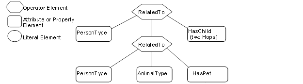
Figure B.8 – Example 4 filter logic tree
Table B.13 describes the elements, operators and operands used in the example.
Table B.13 – Example 4 ContentFilter
|
Element[] |
Operator |
Operand[0] |
Operand[1] |
Operand[2] |
Operand[3] |
|
0 |
RelatedTo |
AttributeOperand = NodeId: 12:PersonType, BrowsePath “.”, Attribute: NodeId |
Element Operand = 1 |
AttributeOperand = NodeId: 12:HasChild, BrowsePath “.”, Attribute: NodeId |
LiteralOperand = ‘2’ |
|
1 |
RelatedTo |
AttributeOperand = NodeId: 12:PersonType, BrowsePath “.”, Attribute: NodeId |
AttributeOperand = NodeId: 12:AnimalType, BrowsePath “.”, Attribute: NodeId |
AttributeOperand = NodeId: 12:HasPet, BrowsePath “.”, Attribute: NodeId |
LiteralOperand = ‘1’ |
The results from this query would contain the QueryDataSets shown in Table B.14. It is worth noting that the pig “Pig1” is referenced as a pet by Sara, but is referenced as a farm animal by Sara’s parent Paul.
Table B.14 – Example 4 QueryDataSets
|
NodeId |
TypeDefinition NodeId |
RelativePath |
Value |
|
12:42 (HFamily1) |
PersonType |
“.12:LastName” |
Hervey |
NOTE The RelativePath column and browse name (in parentheses in the NodeId column) are not in the QueryDataSet and are only shown here for clarity. The TypeDefinition NodeId would be an integer not the symbolic name that is included in the table.
The fifth example provides an illustration of the use of alias.
Example 5: Get the last names of children that have the same first name as a parent of theirs
Table B.15 describes the NodeTypeDescription parameters used in the example.
Table B.15 – Example 5 NodeTypeDescription
|
Type Definition Node |
Include Subtypes |
QueryDataDescription |
||
|
Relative Path |
Attribute |
Index Range |
||
|
PersonType |
FALSE |
“<12:HasChild>12:PersonType. 12:LastName” |
Value |
N/A |
The corresponding ContentFilter is illustrated in Figure B.9.
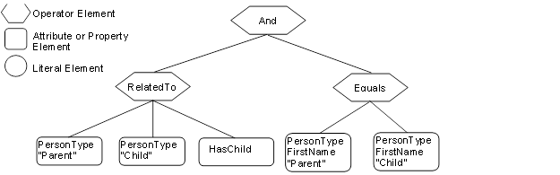
Figure B.9 – Example 5 filter logic tree
In this example, one Reference to PersonType is aliased to “Parent” and another Reference to PersonType is aliased to “Child”. The value of Parent.firstName and Child.firstName are then compared. Table B.16 describes the elements, operators and operands used in the example.
Table B.16 – Example 5 ContentFilter
|
Element[] |
Operator |
Operand[0] |
Operand[1] |
Operand[2] |
Operand[3} |
|
0 |
And |
ElementOperand = 1 |
ElementOperand = 2 |
|
|
|
1 |
RelatedTo |
AttributeOperand = NodeId: 12:PersonType, BrowsePath “.”, Attribute: NodeId, Alias: “Parent” |
AttributeOperand = NodeId: 12:PersonType, BrowsePath “.”, Attribute: NodeId, Alias: “Child” |
AttributeOperand = NodeId: 12:HasChild, Attribute: NodeId |
LiteralOperand = “1” |
|
2 |
Equals |
AttributeOperand = NodeId: 12:PersonType, BrowsePath ““/12:FirstName”, Attribute: Value, Alias: “Parent” |
AttributeOperand = NodeId: 12:PersonType, BrowsePath ““/12:FirstName”, Attribute: Value, Alias: “Child” |
|
|
The results from this query would contain the QueryDataSets shown in Table B.17.
Table B.17 – Example 5 QueryDataSets
|
NodeId |
TypeDefinition NodeId |
RelativePath |
Value |
|
12:42 (HFamily1) |
PersonType |
“<12:HasChild>12:PersonType.12:LastName” |
Hervey |
NOTE The RelativePath column and browse name (in parentheses in the NodeId column) are not in the QueryDataSet and are only shown here for clarity. The TypeDefinition NodeId would be an integer not the symbolic name that is included in the table.
The sixth example provides an illustration a different type of request, one in which the Client is interested in displaying part of the AddressSpace of the Server. This request includes listing a Reference as something that is to be returned.
Example 6: Get PersonType.NodeId, AnimalType.NodeId, PersonType.HasChild Reference, PersonType.HasAnimal Reference where a person has a child who has a Animal.
Table B.18 describes the NodeTypeDescription parameters used in the example.
Table B.18 – Example 6 NodeTypeDescription
|
Type Definition Node |
Include Subtypes |
QueryDataDescription |
||
|
Relative Path |
Attribute |
Index Range |
||
|
PersonType |
FALSE |
“.12:NodeId” |
value |
N/A |
|
<12:HasChild>12:PersonType<12:HasAnimal>12:AnimalType.NodeId |
value |
N/A |
||
|
<12:HasChild> |
value |
N/A |
||
|
<12:HasChild>12:PersonType<12:HasAnimal> |
value |
N/A |
||
The corresponding ContentFilter is illustrated in Figure B.10.
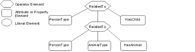
Figure B.10 – Example 6 filter logic tree
Table B.19 describes the elements, operators and operands used in the example.
Table B.19 – Example 6 ContentFilter
|
Element[] |
Operator |
Operand[0] |
Operand[1] |
Operand[2] |
Operand[3] |
|
0 |
RelatedTo |
AttributeOperand = NodeId: 12:PersonType, BrowsePath “.”, Attribute: NodeId |
ElementOperand = 1 |
AttributeOperand = Node: 12:HasChild, BrowsePath “.”,Attribute:NodeId |
LiteralOperand = ‘1’ |
|
1 |
RelatedTo |
AttributeOperand = NodeId: 12:PersonType, BrowsePath “.”, Attribute: NodeId |
AttributeOperand = NodeId: 12:AnimalType, BrowsePath “.”, Attribute: NodeId |
AttributeOperand = NodeId: 12:HasAnimal, BrowsePath “.”, Attribute: NodeId |
LiteralOperand = ‘1’ |
The results from this query would contain the QueryDataSets shown in Table B.20.
Table B.20 – Example 6 QueryDataSets
|
NodeId |
TypeDefinition NodeId |
RelativePath |
Value |
|
12:42 (HFamily1) |
PersonType |
“.NodeId” |
12:42 (HFamily1) |
|
<12:HasChild>12:PersonType<12:HasAnimal> 12:AnimalType.NodeId |
12:91 (Pig1) |
||
|
<12:HasChild> |
HasChild ReferenceDescription |
||
|
<12:HasChild>12:PersonType<12:HasAnimal> |
HasFarmAnimal ReferenceDescription |
||
|
12:48 (HFamily2) |
PersonType |
“.NodeId” |
12:48 (HFamily2) |
|
<12:HasChild>12:PersonType<12:HasAnimal> 12:AnimalType.NodeId |
12:91 (Pig1) |
||
|
<12:HasChild> |
HasChild ReferenceDescription |
||
|
<12:HasChild>12:PersonType<12:HasAnimal> |
HasPet ReferenceDescription |
NOTE The RelativePath and browse name (in parentheses) is not in the QueryDataSet and is only shown here for clarity and the TypeDefinition NodeId would be an integer, not the symbolic name that is included in the table. The value field would in this case be the NodeId where it was requested, but for the example the browse name is provided in parentheses and in the case of Reference types on the browse name is provided. For the References listed in Table B.20, the value would be a ReferenceDescription which are described in 7.30.
Table B.21 provides an example of the same QueryDataSet as shown in Table B.20 without any additional fields and minimal symbolic Ids. There is an entry for each requested Attribute, in the cases where an Attribute would return multiple entries the entries are separated by comas. If a structure is being returned then the structure is enclosed in square brackets. In the case of a ReferenceDescription the structure contains a structure and DisplayName and BrowseName are assumed to be the same and defined in Figure B.4.
Table B.21 – Example 6 QueryDataSets without additional information
|
NodeId |
TypeDefinition NodeId |
Value |
|
12:42 |
PersonType |
12:42 |
|
12:91 |
||
|
[HasChild,TRUE,[48,HFamily2,HFamily2,PersonType]], |
||
|
[HasFarmAnimal,TRUE[91,Pig1,Pig1,PigType] |
||
|
12:48 |
PersonType |
12:54 |
|
12:91 |
||
|
[HasChild,TRUE,[ 54,HFamily3,HFamily3,PersonType]] |
||
|
[HasPet, TRUE,[ 91,Pig1,Pig1,PigType]] |
The PersonType, HasChild, PigType, HasPet, HasFarmAnimal identifiers used in the above table would be translated to actual ExpandedNodeId.
The seventh example provides an illustration a request in which a Client wants to display part of the AddressSpace based on a starting point that was obtained via browsing. This request includes listing References as something that is to be returned. In this case the Person Browsed to Area2 and wanted to Query for information below this starting point.
Example 7: Get PersonType.NodeId, AnimalType.NodeId, PersonType.HasChild Reference, PersonType.HasAnimal Reference where the person is in Area2 (Cleveland nodes) and the person has a child.
Table B.22 describes the NodeTypeDescription parameters used in the example.
Table B.22 – Example 7 NodeTypeDescription
|
Type Definition Node |
Include Subtypes |
QueryDataDescription |
||
|
Relative Path |
Attribute |
Index Range |
||
|
PersonType |
FALSE |
“.NodeId” |
Value |
N/A |
|
<12:HasChild> |
Value |
N/A |
||
|
<12:HasAnimal>NodeId |
Value |
N/A |
||
|
<12:HasAnimal> |
Value |
N/A |
||
The corresponding ContentFilter is illustrated in Figure B.11. Note that the Browse call would typically return a NodeId, thus the first filter is for the BaseObjectType with a NodeId of 95 where 95 is the NodeId associated with the Area2 node, all Nodes descend from BaseObjectType, and NodeId is a base Property so this filter will work for all Queries of this nature.
Figure B.11 – Example 7 filter logic tree
Table B.23 describes the elements, operators and operands used in the example.
Table B.23 – Example 7 ContentFilter
|
Element[] |
Operator |
Operand[0] |
Operand[1] |
Operand[2] |
Operand[3] |
|
0 |
RelatedTo |
ElementOperand = 2 |
ElementOperand = 1 |
AttributeOperand = Node:HierachicalReference, BrowsePath “.”, Attribute:NodeId |
LiteralOperand = ‘1’ |
|
1 |
RelatedTo |
AttributeOperand = NodeId: 12:PersonType, BrowsePath “.”, Attribute: NodeId |
AttributeOperand = NodeId: 12:PersonType, BrowsePath “.”, Attribute: NodeId |
AttributeOperand = NodeId: 12:HasChild, BrowsePath “.”, Attribute: NodeId |
LiteralOperand = ‘1’ |
|
2 |
Equals |
AttributeOperand = NodeId: BaseObjectType, BrowsePath “.”, Attribute: NodeId, |
LiteralOperand = ‘95 |
|
|
The results from this Query would contain the QueryDataSets shown in Table B.24.
Table B.24 – Example 7 QueryDataSets
|
NodeId |
TypeDefinition NodeId |
RelativePath |
Value |
|
12:42 (HFamily1) |
PersonType |
“.NodeId” |
12:42 (HFamily1) |
|
<12:HasChild> |
HasChild ReferenceDescription |
||
|
<12:HasAnimal>12:AnimalType.NodeId |
NULL |
||
|
<12:HasAnimal> |
HasFarmAnimal ReferenceDescription |
||
|
12:48 (HFamily2) |
PersonType |
“.NodeId” |
12:48 (HFamily2) |
|
<12:HasChild> |
HasChild ReferenceDescription |
||
|
<12:HasAnimal>12:AnimalType.NodeId |
12:91 (Pig1) |
||
|
<12:HasAnimal> |
HasFarmAnimal ReferenceDescription |
NOTE The RelativePath and browse name (in parentheses) is not in the QueryDataSet and is only shown here for clarity and the TypeDefinition NodeId would be an integer not the symbolic name that is included in the table. The value field would in this case be the NodeId where it was requested, but for the example the browse name is provided in parentheses and in the case of Reference types on the browse name is provided. For the References listed in Table B.24, the value would be a ReferenceDescription which are described in 7.30.
The eighth example provides an illustration of a request in which the AddressSpace is restricted by a Server defined View. This request is the same as in the second example which illustrates receiving a list of disjoint Nodes and also illustrates that an array of results can be received. It is important to note that all of the parameters and the ContentFilter are the same, only the View description would be specified as “View1”.
Example 8: Get PersonType.LastName, AnimalType.Name where a person has a child or (a pet is of type cat and has a feeding schedule) limited by the AddressSpace in View1.
The NodeTypeDescription parameters used in the example are described in Table B.25
Table B.25 – Example 8 NodeTypeDescription
|
Type Definition Node |
Include Subtypes |
QueryDataDescription |
||
|
Relative Path |
Attribute |
Index Range |
||
|
PersonType |
FALSE |
“.12:LastName” |
value |
N/A |
|
AnimalType |
TRUE |
“12.Name” |
value |
N/A |
The corresponding ContentFilter is illustrated in Figure B.12.
Figure B.12 – Example 8 filter logic tree
Table B.26 describes the elements, operators and operands used in the example. It is worth noting that a CatType is a subtype of AnimalType.
Table B.26 – Example 8 ContentFilter
|
Element[] |
Operator |
Operand[0] |
Operand[1] |
Operand[2] |
Operand[3] |
|
0 |
Or |
ElementOperand=1 |
ElementOperand = 2 |
|
|
|
1 |
RelatedTo |
AttributeOperand = NodeId: 12:PersonType, BrowsePath “.”, Attribute: NodeId |
AttributeOperand = NodeId: 12:PersonType, BrowsePath “.”, Attribute: NodeId |
AttributeOperand = NodeId: 12:HasChild, BrowsePath “.”, Attribute: NodeId |
LiteralOperand = ‘1’ |
|
2 |
RelatedTo |
AttributeOperand = NodeId: 12:CatType, BrowsePath “.”, Attribute: NodeId |
AttributeOperand = NodeId: 12:FeedingScheduleType, BrowsePath “.”, Attribute: NodeId |
AttributeOperand = NodeId: 12:HasSchedule, BrowsePath “.”, Attribute: NodeId |
LiteralOperand = ‘1’ |
The results from this query would contain the QueryDataSets shown in Table B.27. If this is compared to the result set from example 2, the only difference is the omission of the Cat Nodes. These Nodes are not in the View and thus are not included in the result set.
Table B.27 – Example 8 QueryDataSets
|
NodeId |
TypeDefinition NodeId |
RelativePath |
Value |
|
12:30 (Jfamily1) |
Persontype |
.12:LastName |
Jones |
NOTE The RelativePath column and browse name (in parentheses in the NodeId column) are not in the QueryDataSet and are only shown here for clarity. The TypeDefinition NodeId would be an integer not the symbolic name that is included in the table.
The ninth example provides a further illustration for a request in which the AddressSpace is restricted by a Server defined View. This request is similar to the second example except that some of the requested nodes are expressed in terms of a relative path. It is important to note that the ContentFilter is the same, only the View description would be specified as “View1”.
Example 9: Get PersonType.LastName, AnimalType.Name where a person has a child or (a pet is of type cat and has a feeding schedule) limited by the AddressSpace in View1.
Table B.28 describes the NodeTypeDescription parameters used in the example.
Table B.28 – Example 9 NodeTypeDescription
|
Type Definition Node |
Include Subtypes |
QueryDataDescription |
||||
|
Relative Path |
Attribute |
Index Range |
||||
|
PersonType |
FALSE |
“.NodeId” |
value |
N/A |
||
|
<12:HasChild>12:PersonType<12:HasAnimal>12:AnimalType.NodeId |
value |
N/A |
||||
|
<12:HasChild> |
value |
N/A |
||||
|
<12:HasChild>12:PersonType <12:HasAnimal> |
value |
N/A |
||||
|
PersonType |
FALSE |
“.12:LastName” |
value |
N/A |
||
|
|
|
<12:HasAnimal>12:AnimalType. 12:Name |
value |
N/A |
||
|
AnimalType |
TRUE |
“.12:name” |
value |
N/A |
||
The corresponding ContentFilter is illustrated in Figure B.13
Figure B.13 – Example 9 filter logic tree
Table B.29 describes the elements, operators and operands used in the example.
Table B.29 – Example 9 ContentFilter
|
Element[] |
Operator |
Operand[0] |
Operand[1] |
Operand[2] |
Operand[3] |
|
0 |
Or |
ElementOperand=1 |
ElementOperand = 2 |
|
|
|
1 |
RelatedTo |
AttributeOperand = NodeId: 12:PersonType, BrowsePath “.”, Attribute: NodeId |
AttributeOperand = NodeId: 12:PersonType, BrowsePath “.”, Attribute: NodeId |
AttributeOperand = NodeId: 12:HasChild, BrowsePath “.”, Attribute: NodeId |
LiteralOperand = ‘1’ |
|
2 |
RelatedTo |
AttributeOperand = NodeId: 12:CatType, BrowsePath “.”, Attribute: NodeId |
AttributeOperand = NodeId: 12:FeedingScheduleType, BrowsePath “.”, Attribute: NodeId |
AttributeOperand = NodeId: 12:HasSchedule, BrowsePath “.”, Attribute: NodeId |
LiteralOperand = ‘1’ |
The results from this Query would contain the QueryDataSets shown in Table B.30. If this is compared to the result set from example 2, the Pet Nodes are included in the list, even though they are outside of the View. This is possible since the name referenced via the relative path and the root Node is in the View.
Table B.30 – Example 9 QueryDataSets
|
NodeId |
TypeDefinition NodeId |
RelativePath |
Value |
|
12:30 (Jfamily1) |
PersonType |
. 12:LastName |
Jones |
|
<12:HasAnimal>12:AnimalType. 12:Name |
Rosemary |
||
|
<12:HasAnimal>12:AnimalType. 12:Name |
Basil |
NOTE The RelativePath column and browse name (in parentheses in the NodeId column) are not in the QueryDataSet and are only shown here for clarity. The TypeDefinition NodeId would be an integer not the symbolic name that is included in the table.
______________