|
|
|
|
OPC 10000-6 |
|
|
OPC Unified Architecture Part 6: Mappings
Release 1.05.04 2024-10-15
|

|
|
|
|
OPC 10000-6 |
|
|
OPC Unified Architecture Part 6: Mappings
Release 1.05.04 2024-10-15
|
|
Specification Type |
Industry Standard Specification |
Comments: |
||
|
|
|
|
|
|
|
Document |
OPC 10000-6 |
|
|
|
|
Title: |
OPC Unified Architecture |
Date: |
2024-10-15 |
|
|
|
|
|
|
|
|
Version: |
Release 1.05.04 |
Software |
MS-Word |
|
|
|
|
Source: |
OPC 10000-6 - UA Specification Part 6 - Mappings.docx |
|
|
|
|
|
|
|
|
Author: |
OPC Foundation |
Status: |
Release |
|
|
|
|
|
|
|
CONTENTS
3 Terms, definitions and abbreviated terms
5.1.1 Number, Integer and UInteger
0.1.8 Null, Empty and Zero-Length Arrays
0.1.9 QualifiedName, NodeId and ExpandedNodeId String Encoding
5.1.5 Structure FieldPath Encoding Rules
0.1.16 Structures with optional fields
0.1.24 Structures with optional fields
0.1.30 Structures with optional fields
0.1.33 Application Instance Certificate
0.1.35 Issuer (CA) Certificates
0.1.36 Certificate Revocation List (CRL)
6.4 UTC and International Atomic Time (TAI)
6.5 Issued User Identity Tokens
6.7 OPC UA Secure Conversation
0.1.43 MessageChunks and error handling
0.1.44 Establishing a SecureChannel
0.1.46 Verifying Message Security
6.8 Elliptic Curve Cryptography (ECC)
6.7.2 Secure Channel Handshake
0.1.47 UserIdentityToken Encryption
7.1 OPC UA Connection Protocol
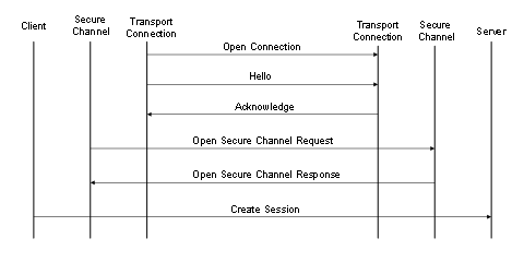
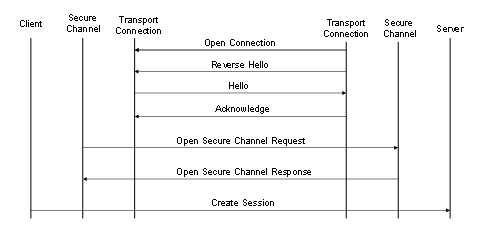
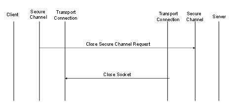
0.1.51 Establishing a connection
8.4 Formal definition of UA Information Model
Annex B (normative) OPC UA NodeSet
Annex C (normative) Type declarations for the OPC UA native Mapping
Annex D (normative) WSDL for the XML Mapping
Annex E (informative) Security settings management
E.4 CertificateStoreIdentifier
E.6 CertificateValidationOptions
Annex F (normative) Information Model XML Schema
Annex G (normative) Mapping to JSON Schema
Annex H (normative) Reversible and NonReversible Encoding (deprecated)
Figure 1 – The OPC UA Stack Overview.................................................. 6
Figure 2 – Encoding Integers in a binary stream...................................... 17
Figure 3 – Encoding Floating Points in a binary stream............................. 17
Figure 4 – Encoding Strings in a binary stream........................................ 18
Figure 5 – Encoding Guids in a binary stream......................................... 19
Figure 6 – Encoding XmlElement in a binary stream................................. 19
Figure 7 – A String NodeId.................................................................. 20
Figure 8 – A Two Byte NodeId............................................................. 21
Figure 9 – A Four Byte NodeId............................................................. 21
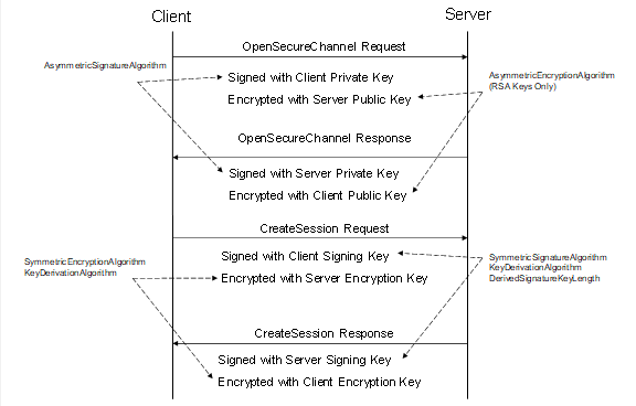
Figure 10 – Security handshake when Creating a Session......................... 54
Figure 11 – MessageChunk for Unauthenticated Encryption Algorithms........ 64
Figure 12 – MessageChunk for Authenticated Encryption Algorithms........... 65
Figure 13 – ECC Key Negotiation......................................................... 73
Figure 14 – Signing and Encryption with Authenticated Encryption.............. 75
Figure 15 – Signing and Encryption with Unauthenticated Encryption.......... 76
Figure 16 – ECC CreateSession/ActivateSession Handshake..................... 77
Figure 17 – OPC UA Connection Protocol Message structure..................... 79
Figure 18 – Client initiated OPC UA Connection Protocol connection........... 83
Figure 19 – Server initiated OPC UA Connection Protocol connection.......... 83
Figure 20 – Closing a OPC UA Connection Protocol connection................. 84
Figure 21 – Scenarios for the HTTPS Transport...................................... 86
Figure 22 – Setting up Communication over a WebSocket......................... 90
Table 1 – Built-in Data Types................................................................ 7
Table 2 – Guid structure....................................................................... 8
Table 3 – Layout of Decimal................................................................ 10
Table 4 – Additional Core Rules........................................................... 11
Table 5 – Description for a NodeId........................................................ 11
Table 6 – Description for a ExpandedNodeId.......................................... 12
Table 7 – Description for a QualifiedName............................................. 13
Table 8 – Examples of XML Encoded Names.......................................... 14
Table 9 – Description for a Structure FieldPath....................................... 14
Table 10 – DataTypeDefinition for a simple Structure............................... 14
Table 11 – Examples of FieldPaths for a Simple Structure......................... 15
Table 12 – DataTypeDefinition for a Complex Structure............................ 15
Table 13 – Examples of FieldPaths in a Complex Structure....................... 16
Table 14 – Supported Floating Point Types............................................ 17
Table 15 – NodeId components............................................................ 19
Table 16 – NodeId DataEncoding values................................................ 20
Table 17 – Standard NodeId Binary DataEncoding................................... 20
Table 18 – Two Byte NodeId Binary DataEncoding................................... 20
Table 19 – Four Byte NodeId Binary DataEncoding.................................. 21
Table 20 – ExpandedNodeId Binary DataEncoding................................... 22
Table 21 – DiagnosticInfo Binary DataEncoding...................................... 22
Table 22 – QualifiedName Binary DataEncoding...................................... 23
Table 23 – LocalizedText Binary DataEncoding....................................... 23
Table 24 – Extension Object Binary DataEncoding................................... 24
Table 25 – Variant Binary DataEncoding................................................ 25
Table 26 – Data Value Binary DataEncoding........................................... 26
Table 27 – Inline Matrix DataEncoding................................................... 27
Table 28 – Sample OPC UA Binary Encoded structure.............................. 28
Table 29 – DataTypeDefinition for “Type1” from Sample........................... 29
Table 30 – DataTypeDefinition for “Type2” from Sample........................... 30
Table 31 – Sample OPC UA Binary Encoded Structure with optional fields... 31
Table 32 – Sample OPC UA Binary Encoded Structure............................. 32
Table 33 – XML Data Type Mappings for Integers.................................... 34
Table 34 – XML Data Type Mappings for Floating Points........................... 34
Table 35 – Components of Enumeration................................................. 41
Table 36 – JSON Object Definition for a StatusCode................................ 46
Table 37 – JSON Object Definition for a DiagnosticInfo............................. 47
Table 38 – JSON Object Definition for a LocalizedText............................. 48
Table 39 – JSON Object Fields used for an ExtensionObject..................... 48
Table 40 – JSON Object Definition for a Variant...................................... 48
Table 41 – JSON Object Definition for a DataValue.................................. 49
Table 42 – JSON Object Definition for a Decimal..................................... 49
Table 43 – JSON Object Definition for an inline Matrix.............................. 50
Table 44 – JSON Encoding Rules for Structures...................................... 50
Table 45 – JSON Object Definition for a Structures with Optional Fields....... 52
Table 46 – JSON Encoding Rules for Structures with Optional Fields.......... 52
Table 47 – JSON Object Definition for a Union........................................ 53
Table 48 – SecurityPolicy.................................................................... 55
Table 49 – Application Instance Certificate............................................. 57
Table 50 – User Certificate.................................................................. 59
Table 51 – Issuer Certificate................................................................ 60
Table 52 – Certificate Revocation List Extensions.................................... 60
Table 53 – JWT UserTokenPolicy......................................................... 61
Table 54 – JWT IssuerEndpointUrl Definition.......................................... 62
Table 55 – Access Token Claims.......................................................... 63
Table 56 – OPC UA Secure Conversation Message Header....................... 65
Table 57 – Asymmetric algorithm Security header.................................... 66
Table 58 – Symmetric algorithm Security header..................................... 67
Table 59 – Sequence header............................................................... 67
Table 60 – Message Footer for Unauthenticated Encryption Algorithms........ 68
Table 61 – Message Footer for Authenticated Encryption Algorithms........... 68
Table 62 – OPC UA Secure Conversation Message abort body.................. 69
Table 63 – OPC UA Secure Conversation OpenSecureChannel Service....... 69
Table 64 – PRF inputs for RSA based SecurityPolicies............................. 71
Table 65 – Cryptography key generation parameters................................ 71
Table 66 – Deriving Client Keys from Keying Material............................... 75
Table 67 – Deriving Server Keys from Keying Material.............................. 75
Table 68 – Creating a Mask for the Initialization Vector............................. 76
Table 69 – Additional Header Key Names.............................................. 78
Table 70 – Deriving Keys from Keying Material....................................... 78
Table 71 – OPC UA Connection Protocol Message header........................ 79
Table 72 – OPC UA Connection Protocol Hello Message........................... 80
Table 73 – OPC UA Connection Protocol Acknowledge Message................ 81
Table 74 – OPC UA Connection Protocol Error Message........................... 81
Table 75 – OPC UA Connection Protocol ReverseHello Message................ 81
Table 76 – Client and Server Handshake during Reverse Connect.............. 83
Table 77 – OPC UA Connection Protocol error codes............................... 85
Table 78 – HTTP Content-Type Header................................................. 87
Table 79 – WebSocket Sub-Protocols.................................................... 91
Table 80 – Well known addresses for Local Discovery Servers................... 92
Table A.1 – Identifiers assigned to Attributes.......................................... 94
Table A.2 – Media Types Assigned to OPC UA Document Formats............. 95
Table E.1 – SecuredApplication.......................................................... 102
Table E.2 – CertificateIdentifier.......................................................... 106
Table E.3 – Structured directory store.................................................. 107
Table E.4 – CertificateStoreIdentifier................................................... 107
Table E.5 – CertificateList................................................................. 108
Table E.6 – CertificateValidationOptions.............................................. 108
Table F.1 – UANodeSet.................................................................... 110
Table F.2 – UANode......................................................................... 112
Table F.3 – Reference...................................................................... 113
Table F.4 – RolePermission............................................................... 113
Table F.5 – UANodeSet Type Nodes................................................... 113
Table F.6 – UANodeSet Instance Nodes............................................... 114
Table F.7 – UAInstance.................................................................... 114
Table F.8 – UAVariable..................................................................... 115
Table F.9 – UAMethod...................................................................... 115
Table F.10 – TranslationType............................................................. 117
Table F.11 – UADataType................................................................. 117
Table F.12 – DataTypeDefinition......................................................... 118
Table F.13 – StructureType Enumeration Mapping................................. 118
Table F.14 – DataTypeField............................................................... 119
Table F.15 – UANodeSetChanges....................................................... 123
Table F.16 – NodesToAdd................................................................. 124
Table F.17 – ReferencesToChange..................................................... 124
Table F.18 – ReferencesToChange..................................................... 124
Table F.19 – NodesToDelete.............................................................. 125
Table F.20 – ReferencesToChange..................................................... 125
Table F.21 – UANodeSetChangesStatus.............................................. 125
Table F.22 – NodeSetStatusList......................................................... 126
Table F.23 – NodeSetStatus.............................................................. 126
Table G.1 – OpenAPI Message Envelope............................................. 128
Table H.1 – JSON Object Definition for a NodeId................................... 129
Table H.2 – JSON Object Definition for an ExpandedNodeId.................... 130
Table H.3 – JSON Object Definition for a StatusCode............................. 130
Table H.4 – JSON Object Definition for a QualifiedName......................... 131
Table H.5 – JSON Object Definition for a LocalizedText.......................... 131
Table H.6 – JSON Object Definition for an ExtensionObject..................... 131
Table H.7 – JSON Object Definition for a Variant................................... 132
Table H.8 – JSON Object Definition for a Union..................................... 132
____________
UNIFIED ARCHITECTURE –
This specification is the specification for developers of OPC UA applications. The specification is a result of an analysis and design process to develop a standard interface to facilitate the development of applications by multiple vendors that shall inter-operate seamlessly together.
Copyright © 2006-2024, OPC Foundation, Inc.
COPYRIGHT RESTRICTIONS
Any unauthorized use of this specification may violate copyright laws, trademark laws, and communications regulations and statutes. This document contains information which is protected by copyright. All Rights Reserved. No part of this work covered by copyright herein may be reproduced or used in any form or by any means--graphic, electronic, or mechanical, including photocopying, recording, taping, or information storage and retrieval systems--without permission of the copyright owner.
OPC Foundation members and non-members are prohibited from copying and redistributing this specification. All copies must be obtained on an individual basis, directly from the OPC Foundation Web site https://www.opcfoundation.org.
PATENTS
The attention of adopters is directed to the possibility that compliance with or adoption of OPC specifications may require use of an invention covered by patent rights. OPC shall not be responsible for identifying patents for which a license may be required by any OPC specification, or for conducting legal inquiries into the legal validity or scope of those patents that are brought to its attention. OPC specifications are prospective and advisory only. Prospective users are responsible for protecting themselves against liability for infringement of patents.
WARRANTY AND LIABILITY DISCLAIMERS
WHILE THIS PUBLICATION IS BELIEVED TO BE ACCURATE, IT IS PROVIDED "AS IS" AND MAY CONTAIN ERRORS OR MISPRINTS. THE OPC FOUDATION MAKES NO WARRANTY OF ANY KIND, EXPRESSED OR IMPLIED, WITH REGARD TO THIS PUBLICATION, INCLUDING BUT NOT LIMITED TO ANY WARRANTY OF TITLE OR OWNERSHIP, IMPLIED WARRANTY OF MERCHANTABILITY OR WARRANTY OF FITNESS FOR A PARTICULAR PURPOSE OR USE. IN NO EVENT SHALL THE OPC FOUNDATION BE LIABLE FOR ERRORS CONTAINED HEREIN OR FOR DIRECT, INDIRECT, INCIDENTAL, SPECIAL, CONSEQUENTIAL, RELIANCE OR COVER DAMAGES, INCLUDING LOSS OF PROFITS, REVENUE, DATA OR USE, INCURRED BY ANY USER OR ANY THIRD PARTY IN CONNECTION WITH THE FURNISHING, PERFORMANCE, OR USE OF THIS MATERIAL, EVEN IF ADVISED OF THE POSSIBILITY OF SUCH DAMAGES.
The entire risk as to the quality and performance of software developed using this specification is borne by you.
RESTRICTED RIGHTS LEGEND
This Specification is provided with Restricted Rights. Use, duplication or disclosure by the U.S. government is subject to restrictions as set forth in (a) this Agreement pursuant to DFARs 227.7202-3(a); (b) subparagraph (c)(1)(i) of the Rights in Technical Data and Computer Software clause at DFARs 252.227-7013; or (c) the Commercial Computer Software Restricted Rights clause at FAR 52.227-19 subdivision (c)(1) and (2), as applicable. Contractor / manufacturer are the OPC Foundation, 16101 N. 82nd Street, Suite 3B, Scottsdale, AZ, 85260-1830.
COMPLIANCE
The OPC Foundation shall at all times be the sole entity that may authorize developers, suppliers and sellers of hardware and software to use certification marks, trademarks or other special designations to indicate compliance with these materials. Products developed using this specification may claim compliance or conformance with this specification if and only if the software satisfactorily meets the certification requirements set by the OPC Foundation. Products that do not meet these requirements may claim only that the product was based on this specification and must not claim compliance or conformance with this specification.
Trademarks
Most computer and software brand names have trademarks or registered trademarks. The individual trademarks have not been listed here.
GENERAL PROVISIONS
Should any provision of this Agreement be held to be void, invalid, unenforceable or illegal by a court, the validity and enforceability of the other provisions shall not be affected thereby.
This Agreement shall be governed by and construed under the laws of the State of Minnesota, excluding its choice or law rules.
This Agreement embodies the entire understanding between the parties with respect to, and supersedes any prior understanding or agreement (oral or written) relating to, this specification.
ISSUE REPORTING
The OPC Foundation strives to maintain the highest quality standards for its published specifications, hence they undergo constant review and refinement. Readers are encouraged to report any issues and view any existing errata here: http://www.opcfoundation.org/errata.
Revision 1.05.04 Highlights
The following table includes the Mantis issues resolved with this revision.
|
Mantis ID |
Scope |
Summary |
Resolution |
|
Clarification |
Is there a missing type XMLElement in Opc.Ua.Types.xsd? |
Prohibited subtypes of XmlElement and marked the built-in type as deprecated in 1.1.11. |
|
|
Errata |
Recursion in DiagnosticInfo/InnerDiagnosticInfo should be limited to lower number than 100 |
Reduced minimum requirement and added a maximum to 5.2.1.12, 5.3.1.13 and 5.4.1.13. |
|
|
Clarification |
(Compact) JSON encoding of variants with default values. |
Added clarification to 5.4.1.17. |
|
|
Clarification |
Self-signed certificates shall have keyCertSign but should not be CA : it is contradictory with the RFC referenced in the spec. |
Added reference in Table 49 to RFC 6818 which explains that the requirement does not contradict RFC 5280. |
|
|
Clarification |
NodeSet XML Specification (Annex F) should clarify where aliases are allowed. |
Added explicit requirements for Aliases to F.2. |
|
|
Clarification |
Description of Reversible vs NonReversible encoding is unclear.. |
Added terms CompactEncoding (3.1.6) and VerboseEncoding (3.1.8). |
|
|
Errata |
XML encoding in UANodeset for unknown Default XML encoding ID. |
Allow DataType Node in XML (5.3.1.16) and JSON (5.4.1.16) encodings. This affects the serialization of Variable Values in UANodeSets (see Annex F). |
|
|
Feature |
Normative BrowseNames that are not used on Types or InstanceDeclarations need to be defined. |
Added DesignToolOnly flag to UAInstance in F.7. |
|
|
Clarification |
Update required for Dimensions of Matrix Structure Field value in Opc.Ua.Types.xsd |
Updated Opc.Ua.Types.xsd. |
|
|
Feature |
JSON Should Allow Defined String Encoding for NodeIds. ExpandedNodeIds and QualifiedNames. |
Updated 1.1.27 to add a v2 encoding that fixes the issues. The v1 encoding will eventually be deprecated. |
|
|
Clarification |
Unclear type for arrays in XML encoding. |
Clarified that the name of elements in structures come from the field name in 1.1.23, 1.1.24 and 1.1.25. |
|
|
Errata |
Require the ReceiverCertificateThumbprint to be set for all ECC policies. |
Updated Table 57 to require the ReceiverCertificateThumbprint when using ECC. |
|
|
Errata |
QualifiedName ABNF is wrong. |
Changed rules in Table 7. |
|
|
Clarification |
Clarify if Number/UInteger/Integer in a complex type need to set AllowSubTypes. |
Updated text in Table F.14. |
|
|
Errata |
WebSocket and HTTPS mapping needs updates for OpenAPI mapping for JSON messages. |
Updated text in 7.4 and 7.5 |
|
|
Clarification |
Table 5 contains unused syntax rules. |
Updated text in 7.4 and 7.5 |
OPC Unified Architecture
Part 6: Mappings Specification
This part of OPC Unified Architecture (OPC UA) specifies the mapping between the security model described in OPC 10000-2, the abstract service definitions specified in OPC 10000-4, the data structures defined in OPC 10000-5 and the physical network protocols that can be used to implement the OPC UA specification.
The following documents, in whole or in part, are normatively referenced in this document and are indispensable for its application. For dated references, only the edition cited applies. For undated references, the latest edition of the referenced document (including any amendments) applies.
OPC 10000-1, OPC Unified Architecture - Part 1: Overview and Concepts
http://www.opcfoundation.org/UA/Part1/
OPC 10000-2, OPC Unified Architecture - Part 2: Security Model
http://www.opcfoundation.org/UA/Part2/
OPC 10000-3, OPC Unified Architecture - Part 3: Address Space Model
http://www.opcfoundation.org/UA/Part3/
OPC 10000-4, OPC Unified Architecture - Part 4: Services
http://www.opcfoundation.org/UA/Part4/
OPC 10000-5, OPC Unified Architecture - Part 5: Information Model
http://www.opcfoundation.org/UA/Part5/
OPC 10000-6, OPC Unified Architecture - Part 6: Mappings
http://www.opcfoundation.org/UA/Part6/
OPC 10000-7, OPC Unified Architecture - Part 7: Profiles
http://www.opcfoundation.org/UA/Part7/
OPC 10000-9, OPC Unified Architecture - Part 9: Alarms and Conditions
http://www.opcfoundation.org/UA/Part9/
OPC 10000-12, OPC Unified Architecture - Part 12: Discovery and Global Services
http://www.opcfoundation.org/UA/Part12/
OPC 10000-14, OPC Unified Architecture - Part 14: PubSub
http://www.opcfoundation.org/UA/Part14/
OPC 10000-18, OPC Unified Architecture - Part 18: Role-Based Security
http://www.opcfoundation.org/UA/Part18/
OPC 10000-21, OPC Unified Architecture - Part 21: Device Onboarding
http://www.opcfoundation.org/UA/Part21/
XML Schema Part 2: XML Schema Part 2: Datatypes
http://www.w3.org/TR/xmlschema-2/
SOAP Part 1, SOAP Version 1.2 Part 1: Messaging Framework
http://www.w3.org/TR/soap12-part1/
WS Addressing, Web Services Addressing (WS-Addressing)
http://www.w3.org/Submission/ws-addressing/
TLS, RFC 8446 – The Transport Layer Security (TLS) Protocol Version 1.3
https://datatracker.ietf.org/doc/html/rfc8446
X.509 v3, ISO/IEC 9594-8 (ITU-T Rec. X.509), Information technology – Open Systems
Interconnection – The Directory: Public-key and attribute certificate frameworks
https://www.iso.org/standard/72557.html
HTTP, Hypertext Transfer Protocol (HTTP/1.1): Message Syntax and Routing
https://datatracker.ietf.org/doc/html/rfc7230
HTTPS, HTTP Over TLS
http://www.ietf.org/rfc/rfc2818.txt
Base64, The Base16, Base32, and Base64 Data Encodings
https://datatracker.ietf.org/doc/html/rfc4648
X690, ISO/IEC 8825-1 (ITU-T Rec. X.690), Information technology – ASN.1 encoding rules: Specification of Basic Encoding Rules (BER), Canonical Encoding Rules (CER) and Distinguished Encoding Rules (DER)
https://www.iso.org/standard/35688.html
X200, ISO/IEC 7498-1 (ITU-T Rec. X.200), Information technology – Open Systems Interconnection – Basic Reference Model: The Basic Model
https://www.iso.org/standard/20269.html
IEEE 754, 60559-2020 - ISO/IEC/IEEE International Standard - Standard for Floating-Point Arithmetic
https://ieeexplore.ieee.org/document/9091348
HMAC, Keyed-Hashing for Message Authentication
https://datatracker.ietf.org/doc/html/rfc2104
PKCS #1, RSA Cryptography Specifications Version 2.2
https://datatracker.ietf.org/doc/html/rfc8017
PKCS #12, Personal Information Exchange Syntax v1.1
https://datatracker.ietf.org/doc/html/rfc7292
FIPS 180-4, Secure Hash Standard (SHS)
https://csrc.nist.gov/publications/detail/fips/180/4/final
FIPS 197, Advanced Encryption Standard (AES)
https://www.nist.gov/publications/advanced-encryption-standard-aes
UTF-8, UTF-8, a transformation format of ISO 10646
https://datatracker.ietf.org/doc/html/rfc3629
RFC 5280, Internet X.509 Public Key Infrastructure Certificate
and Certificate Revocation List (CRL) Profile
https://datatracker.ietf.org/doc/html/rfc5280
RFC 6818, Updates to the Internet X.509 Public Key Infrastructure
Certificate and Certificate Revocation List (CRL) Profile
https://datatracker.ietf.org/doc/html/rfc6818
RFC 4514, LDAP: String Representation of Distinguished Names
https://datatracker.ietf.org/doc/html/rfc4514
NTP, Network Time Protocol Version 4: Protocol and Algorithms Specification
https://datatracker.ietf.org/doc/html/rfc5905
RFC 3986, Uniform Resource Identifier (URI): Generic Syntax
https://datatracker.ietf.org/doc/html/rfc3986
RFC 8141, Uniform Resource Names (URNs)
https://datatracker.ietf.org/doc/html/rfc8141
RFC 6455, The WebSocket Protocol
https://datatracker.ietf.org/doc/html/rfc6455
RFC 8259, The JavaScript Object Notation (JSON) Data Interchange Format
https://datatracker.ietf.org/doc/html/rfc8259
RFC 7523, JSON Web Token (JWT) Profile for OAuth 2.0 Client Authentication and
Authorization Grants
https://datatracker.ietf.org/doc/html/rfc7523
RFC 5392, The OAuth 2.0 Authorization Framework
https://datatracker.ietf.org/doc/html/rfc6749
OpenID-Core, OpenID Connect Core 1.0
http://openid.net/specs/openid-connect-core-1_0.html
OpenID-Discovery, OpenID Connect Discovery 1.0
https://openid.net/specs/openid-connect-discovery-1_0.html
RFC 6960, X.509 Internet Public Key Infrastructure – Online Certificate Status Protocol – OCSP
https://datatracker.ietf.org/doc/html/rfc6960
RFC 5869, HMAC-based Extract-and-Expand Key Derivation Function (HKDF)
https://datatracker.ietf.org/doc/html/rfc5869
RFC 8422, Elliptic Curve Cryptography (ECC) Cipher Suites
https://datatracker.ietf.org/doc/html/rfc8422
RFC 6750, The OAuth 2.0 Authorization Framework: Bearer Token Usage
https://datatracker.ietf.org/doc/html/rfc6750
ISO 8601-1, Date and time - Representations for information interchange - Part 1: Basic rules
https://www.iso.org/standard/70907.html
RFC 5234, Augmented BNF for Syntax Specifications: ABNF
https://datatracker.ietf.org/doc/html/rfc5234
RFC 4151, The 'tag' URI Scheme
https://datatracker.ietf.org/doc/html/rfc4151
SemVer, Semantic Versioning 2.0.0
https://semver.org/spec/v2.0.0.html
OpenAPI, OpenAPI Specification v3.1.0
https://spec.openapis.org/oas/latest.html
JSON Schema, JSON Schema 2020-12
https://json-schema.org/specification
RFC 1952: GZIP file format specification version 4.3
https://www.rfc-editor.org/rfc/rfc1952
For the purposes of this document the terms and definitions given in OPC 10000-1, OPC 10000-2 and OPC 10000-3 as well as the following apply.
3.1.1
CertificateDigest
short identifier used to uniquely identify an X.509 v3Certificate.
Note 1 to entry: This is the SHA1 hash of DER encoded form of the Certificate.
3.1.2
DataEncoding
way to serialize messages and data structures.
3.1.3
DefaultValue
a value that is used when no other value is known or available.
3.1.4
DevelopmentPlatform
suite of tools and/or programming languages used to create software.
3.1.5
Mapping
specification on how to implement an OPC UA feature with a specific technology.
Note 1 to entry: For example, the OPC UA Binary Encoding is a Mapping that specifies how to serialize OPC UA data structures as sequences of bytes.
VerboseEncoding
A DataEncoding where the serialized form does not omit optional or default values and adds additional descriptive text.
Note 1 to entry: VerboseEncodings are used when the consumers of the data do not have access to schema information and rely on the self-describing nature of DataEncodings such as JSON
Note 2 to entry: A VerboseEncoding is only defined for the JSON DataEncoding.
3.1.7
OctetString
a sequence of zero or more octets without any length prefix.
Note 1 to entry: an OctetString is not defined as a DataType and only used in this document when a ByteString is not appropriate.
CompactEncoding
A DataEncoding where encoding the serialized form omits optional and default values.
Note 1 to entry: All DataEncodings are CompactEncodings unless otherwise stated.
3.1.9
SecurityProtocol
Protocol which ensures the integrity and privacy of UA Messages that are exchanged between OPC UA applications
3.1.10
StackProfile
combination of DataEncodings, SecurityProtocol and TransportProtocol Mappings
Note 1 to entry: OPC UA applications implement one or more StackProfiles and can only communicate with OPC UA applications that support a StackProfile that they support.
3.1.11
TransportConnection
full-duplex communication link established between OPC UA applications.
Note 1 to entry: A TCP/IP socket is an example of a TransportConnection.
3.1.12
TransportProtocol
way to exchange serialized OPC UA Messages between OPC UA applications
AEAD Authenticated Encryption with Associated Data
API Application Programming Interface
ASN.1 Abstract Syntax Notation #1 (used in X690)
CSV Comma Separated Value (File Format)
DNS Domain Name Service
ECC Elliptic Curve Cryptography
HTTP Hypertext Transfer Protocol
HTTPS Secure Hypertext Transfer Protocol
IANA Internet Assigned Numbers Authority
IPSec Internet Protocol Security
NAT Network Address Translation
OID Object Identifier (used with ASN.1)
PRF Pseudo Random Function
RSA Rivest, Shamir and Adleman [Public Key Encryption System]
SHA1 Secure Hash Algorithm
SOAP Simple Object Access Protocol
SSL Secure Sockets Layer (Defined in TLS)
TCP Transmission Control Protocol
TLS Transport Layer Security (Defined in TLS)
UA Unified Architecture
UACP OPC UA Connection Protocol
UASC OPC UA Secure Conversation
WS-* XML Web Services Specifications
XML Extensible Markup Language
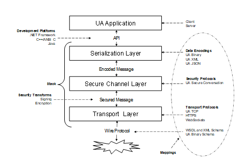
Other parts of the OPC 10000 series are written to be independent of the technology used for implementation. This approach means OPC UA is a flexible specification that will continue to be applicable as technology evolves. On the other hand, this approach means that it is not possible to build an OPC UA application with the information contained in OPC 10000-1 through to OPC 10000-5 because important implementation details have been left out.
This document defines Mappings between the abstract specifications and technologies that can be used to implement them. The Mappings are organized into three groups: DataEncodings, SecurityProtocols and TransportProtocols. Different Mappings are combined together to create StackProfiles. All OPC UA applications shall implement at least one StackProfile and can only communicate with other OPC UA applications that implement the same StackProfile.
This document defines the DataEncodings in Clause 5, the SecurityProtocols in 5.4 and the TransportProtocols in 1.1.46. The StackProfiles are defined in OPC 10000-7.
All communication between OPC UA applications is based on the exchange of Messages. The parameters contained in the Messages are defined in OPC 10000-4; however, their format is specified by the DataEncoding and TransportProtocol. For this reason, each Message defined in OPC 10000-4 shall have a normative description which specifies exactly what shall be put on the wire. The normative descriptions are defined in the annexes.
A Stack is a collection of software libraries that implement one or more StackProfiles. The interface between an OPC UA application and the Stack is a non-normative API which hides the details of the Stack implementation. An API depends on a specific DevelopmentPlatform. Note that the datatypes exposed in the API for a DevelopmentPlatform may not match the datatypes defined by the specification because of limitations of the DevelopmentPlatform. For example, Java Progamming Language does not support an unsigned integer which means that any API will need to map unsigned integers onto a signed integer type.
Figure 1 illustrates the relationships between the different concepts defined in this document.
Figure 1 – The OPC UA Stack Overview
The layers described in this specification do not correspond to layers in the OSI 7-layer model [X200]. Each OPC UA StackProfile should be treated as a single Layer 7 (application) protocol that is built on an existing Layer 5, 6 or 7 protocol such as TCP/IP, TLS or HTTP. The SecureChannel layer is always present even if the SecurityMode is None. In this situation, no security is applied but the SecurityProtocol implementation shall maintain a logical channel with a unique identifier. Users and administrators are expected to understand that a SecureChannel with SecurityMode set to None cannot be trusted unless the application is operating on a physically secure network or a low-level protocol such as IPSec is being used.
This document defines three DataEncodings: OPC UA Binary, OPC UA XML and OPC UA JSON. It describes how to construct Messages using each of these encodings.
All OPC UA DataEncodings are based on rules that are defined for a standard set of built-in types. These built-in types are then used to construct structures, arrays and Messages. The built-in types are described in Table 1.
Table 1 – Built-in Data Types
|
ID |
Name |
Nullable |
Default |
Description |
|
1 |
Boolean |
No |
false |
A two-state logical value (true or false). |
|
2 |
SByte |
No |
0 |
An integer value between −128 and 127 inclusive. |
|
3 |
Byte |
No |
0 |
An integer value between 0 and 255 inclusive. |
|
4 |
Int16 |
No |
0 |
An integer value between −32768 and 32767 inclusive. |
|
5 |
UInt16 |
No |
0 |
An integer value between 0 and 65535 inclusive. |
|
6 |
Int32 |
No |
0 |
An integer value between −2,147,483,648 and 2,147,483,647 inclusive. |
|
7 |
UInt32 |
No |
0 |
An integer value between 0 and 4,294,967,295 inclusive. |
|
8 |
Int64 |
No |
0 |
An integer value between −9,223,372,036,854,775,808 and 9,223,372,036,854,775,807 inclusive. |
|
9 |
UInt64 |
No |
0 |
An integer value between 0 and 18,446,744,073,709,551,615 inclusive. |
|
10 |
Float |
No |
0 |
An IEEE single precision (32 bit) floating point value. |
|
11 |
Double |
No |
0 |
An IEEE double precision (64 bit) floating point value. |
|
12 |
String |
Yes |
null |
A sequence of Unicode characters. |
|
13 |
DateTime |
Yes |
DateTime.MinValue (see 1.1.4) |
An instance in time. |
|
14 |
Guid |
Yes |
All zeros |
A 16-byte value that can be used as a globally unique identifier. |
|
15 |
ByteString |
Yes |
null |
A sequence of octets. |
|
16 |
XmlElement |
Yes |
null |
A sequence of Unicode characters that is an XML element. This built-in type shall not have subtypes. |
|
17 |
NodeId |
Yes |
All fields set to default. |
An identifier for a node in the address space of an OPC UA Server. |
|
18 |
ExpandedNodeId |
Yes |
All fields set to default. |
A NodeId that allows the namespace URI to be specified instead of an index. |
|
19 |
StatusCode |
No |
Good |
A numeric identifier for an error or condition that is associated with a value or an operation. |
|
20 |
QualifiedName |
Yes |
All fields set to default. |
A name qualified by a namespace. |
|
21 |
LocalizedText |
Yes |
All fields set to default. |
Human readable text with an optional locale identifier. |
|
22 |
ExtensionObject |
Yes |
All fields set to default. |
A structure that contains an application specific data type that may not be recognized by the receiver. |
|
23 |
DataValue |
Yes |
All fields set to default. |
A data value with an associated status code and timestamps. |
|
24 |
Variant |
Yes |
Null |
A union of all of the types specified above. |
|
25 |
DiagnosticInfo |
Yes |
No fields specified. |
A structure that contains detailed error and diagnostic information associated with a StatusCode. |
Most of these data types are the same as the abstract types defined in OPC 10000-3 and OPC 10000-4. However, the ExtensionObject and Variant types are defined in this document. In addition, this document defines a representation for the Guid type defined in OPC 10000-3.
The Nullable column indicates whether a ‘null’ value exists for the DataType in all DataEncodings. A ‘null’ value is a value that is equavalent ‘no value specified’. A nullable type with a default value means the default value shall be interpreted equivalent to a null.
The Default column specifies the default value for the type if a default value is needed. The default value for all arrays is ‘null’.
A Guid is a 16-byte globally unique identifier with the layout shown in Table 2.
Table 2 – Guid structure
|
Component |
Data Type |
|
Data1 |
UInt32 |
|
Data2 |
UInt16 |
|
Data3 |
UInt16 |
|
Data4 |
Byte [8] |
Guid values may be represented as a string in this form:
<Data1>-<Data2>-<Data3>-<Data4[0:1]>-<Data4[2:7]>
where Data1 is 8 characters wide, Data2 and Data3 are 4 characters wide and each Byte in Data4 is 2 characters wide. Each value is formatted as a hexadecimal number with padded zeros. A typical Guid value would look like this when formatted as a string:
C496578A-0DFE-4B8F-870A-745238C6AEAE
DateTime values have different ranges on different DevelopmentPlatforms. To ensure interoperablity two named values are defined:
“DateTime.MinValue” is the earliest value that can be represented;
“DateTime.MaxValue” is the latest value that can be represented.
If the range supported by the DataEncoding is outside of the range supported by a DevelopmentPlatform then decoders shall replace any below range values with DateTime.MinValue and any above range values with DateTime.MaxValue for the DevelopmentPlatform.
If the range supported by a DevelopmentPlatform is outside of the range supported by a DataEncoding then encoders shall replace any below range values with DateTime.MinValue and any above range values with DateTime.MaxValue for the DataEncoding.
The representation of a DateTime on a DevelopmentPlatform also has a maximum precision. Decoders shall truncate DateTime values that exceed the supported precision. All DevelopmentPlatforms shall support a precision of at least 1ms.
The DataValue built-in type adds additional fields for Picoseconds. If a DevelopmentPlatform cannot support the full precision of DateTime values allowed by the DataEncoding then it should expand the size of its internal representation of Picoseconds field to preserve the full precision of the DateTime. If it does not do this it shall set the Picoseconds to 0.
The Picoseconds shall be set to 0 when the DateTime value is DateTime.MinValue or DateTime.MaxValue.
Concrete examples can be found in 5.2.1.5.
A ByteString is structurally the same as a one-dimensional array of Byte. It is represented as a distinct built-in data type because it allows encoders to optimize the transmission of the value. However, some DevelopmentPlatforms will not be able to preserve the distinction between a ByteString and a one-dimensional array of Byte.
If a decoder for DevelopmentPlatform cannot preserve the distinction it shall convert all one-dimensional arrays of Byte to ByteStrings.
Each element in a one-dimensional array of ByteString can have a different length which means is structurally different from a two-dimensional array of Byte where the length of each dimension is the same. This means decoders shall preserve the distinction between two or more dimension arrays of Byte and one or more dimension arrays of ByteString.
If a DevelopmentPlatform does not support unsigned integers, then it will have to represent ByteStrings as arrays of SByte. In this case, the requirements for Byte would then apply to SByte.
Number, Integer and UInteger are abstract simple types defined in OPC 10000-3. When these types are used in Structure fields, the field value is encoded as a Variant.
Structures are sequences of name value pairs defined by the DataTypeDefinition Attribute in OPC 10000-3. Each DataEncoding describes how to use the DataTypeDefinition to serialize Structures. Subtypes of Structure extend the parent by adding additional name-value pairs to the sequence.
If a DataTypeDefinition sets the StructureType to StructureWithSubtypedValues then any field with a subtype of Structure DataType and IsOptional=TRUE allows the type and any subtype of the field’s DataType to be present in the field. In these cases, the values are serialized as an ExtensionObject. If IsOptional=FALSE then the field value is encoded directly according to the rules for the DataEncoding.
A field is serialized as an ExtensionObject if a field has a DataType set explicitly to Structure.
Unions are special subtypes of Structure where only one field value is encoded. All subtypes of Union are concrete. The remainder of the rules for Structure also apply to Unions.
An ExtensionObject is a container for any Structure and Union DataTypes.
The ExtensionObject contains a complex value serialized as a sequence of other DataTypes. It also contains an identifier which indicates what data it contains and how it is encoded.
There are four primary use cases where ExtensionObjects appear:
· When encoding a top-level DataType as a Service Request or Response;
· When encoding a Structure value inside a Variant;
· When encoding a field value in a Structure where the field DataType is Structure.
· When encoding a field value in a Structure where AllowSubTypes=TRUE (see F.12).
In all of these cases, the ExtensionObject provides an identifier that allows a decoder to know if it understands the Structure contained with it and a length that allows the Structure to be skipped if it is not recognized.
Structured DataTypes are represented in a Server address space as sub-types of the Structure DataType. The DataEncodings available for any given Structured DataTypes are represented as a DataTypeEncoding Object in the Server AddressSpace. The NodeId for the DataTypeEncoding Object is the identifier stored in the ExtensionObject. OPC 10000-3 describes how DataTypeEncoding Nodes are related to other Nodes of the AddressSpace.
Elements of an array of ExtensionObjects may have different DataTypeEncoding NodeIds specified. In some cases, this will be invalid, however, it is the responsibility of the application layer to enforce whatever constraints are imposed by the Information Model on a given array. Decoders shall accept any valid ExtensionObject as an array element.
Server implementers should use namespace qualified numeric NodeIds for any DataTypeEncoding Objects they define. This will minimize the overhead introduced by packing Structured DataType values into an ExtensionObject.
ExtensionObjects and Variants allow unlimited nesting which could result in stack overflow errors even if the message size is less than the maximum allowed. Decoders shall support at least 100 nesting levels. Decoders shall report an error if the number of nesting levels exceeds what it supports.
A Variant is a union of all built-in data types including an ExtensionObject. Variants can also contain arrays of any of these built-in types. Variants are used to store any value or parameter with a data type of BaseDataType or one of its subtypes.
Variants can be empty. An empty Variant is described as having a null value and should be treated like a null column in a SQL database. A null value in a Variant may not be the same as a null value for data types that support nulls such as Strings. Some DevelopmentPlatforms may not be able to preserve the distinction between a null for a DataType and a null for a Variant, therefore, applications shall not rely on this distinction. This requirement also means that if an Attribute supports the writing of a null value it shall also support writing of an empty Variant and vice versa.
Variants can contain arrays of Variants but they cannot directly contain another Variant.
DiagnosticInfo types only have meaning when returned in a response message with an associated StatusCode and table of strings. As a result, Variants cannot contain instances of DiagnosticInfo.
Values of Attributes are always returned in instances of DataValues. Therefore, the DataType of an Attribute cannot be a DataValue. Variants can contain DataValue when used in other contexts such as Method Arguments or PubSub Messages. The Variant in a DataValue cannot, directly or indirectly, contain another DataValue.
ExtensionObjects and Variants allow unlimited nesting which could result in stack overflow errors even if the message size is less than the maximum allowed. Decoders shall support at least 100 nesting levels. Decoders shall report an error if the number of nesting levels exceeds what it supports.
A Decimal is a high-precision signed decimal number. It consists of an arbitrary precision integer unscaled value and an integer scale. The scale is the inverse power of ten that is applied to the unscaled value.
A Decimal has the fields described in Table 3.
Table 3 – Layout of Decimal
|
Field |
Type |
Description |
|
TypeId |
NodeId |
The identifier for the Decimal DataType. |
|
Encoding |
Byte |
This value is always 1. |
|
Length |
Int32 |
The length of the Scale and Value fields in bytes. |
|
Scale |
Int16 |
A signed integer representing scale which is the inverse power of ten that is applied to the unscaled value. i.e., the decimal number of the value multiplied by 10-scale The integer is encoded starting with the least significant bit. |
|
Value |
OctetString |
A 2-complement signed integer representing the unscaled value. The number of bytes is the value of the Length field minus size of the Scale field. The integer is encoded with the least significant byte first. |
When a Decimal is encoded in a Variant the built-in type is set to ExtensionObject. Decoders that do not understand the Decimal type shall treat it like any other unknown Structure and pass it on to the application. Decoders that do understand the Decimal can parse the value and use any construct that is suitable for the DevelopmentPlatform. Note that a Decimal is like a built-in type and a DevelopmentPlatform has to have hardcoded knowledge of the type. No Structure metadata is published for this type.
If a Decimal is embedded in another Structure then the DataTypeDefinition for the field shall specify the NodeId of the Decimal Node as the DataType. If a Server publishes an OPC Binary type description for the Structure then the type description shall set the DataType for the field to ExtensionObject.
The terms null, empty and zero-length are used to describe array values (Strings are arrays of characters and ByteStrings are arrays of Bytes for purposes of this discussion). A null array has no value. A zero-length or empty array is an array with 0 elements. Some DataEncodings will allow the distinction to be preserved on the wire, however, not all DevelopmentPlatforms will be able to preserve the distinction. For this reason, null, empty and zero length arrays are semantically the same for all DataEncodings. Decoders shall be able to handle all variations supported by the DataEncoding, however, decoders are not required to preserve the distinction. When testing for equality, applications shall treat null and empty arrays as equal. When a DevelopmentPlatform supports the distinction, writing and reading back an array value may result in null array becoming an empty array or vice versa.
QualifiedNames, NodeIds and ExpandedNodeIds optimize representation of NamespaceUris by using a NamespaceIndex to reference the location of the URI in a NamespaceTable. The NamespaceTable to use is known from the context. For example, when a Client establishes a Session with a Server, the Server supplies the NamespaceTable that is used for all exchanges within that Session. Another example, is when a Publisher publishes DataSetMetadata messages, the NamespaceTable is provided as part of the message.
However, there are other scenarios where there is no obvious context that can be used to store the NamespaceTable, such as column in a database table, so it is necessary to provide a self-contained representation of these DataTypes. This clause defines a normative String representation using the ABNF like notation (see RFC 5234). Table 4 defines additional core rules used in these definitions.
Table 4 – Additional Core Rules
|
UNICODE |
Any Unicode character other than a Control character. |
|
CONTROL |
Any Unicode Control character (includes nulls, carriage returns, tabs and new lines). |
|
URI |
A string that conforms to RFC 3986. |
|
ENCODEDURI |
A URI which has the RFC 3986 Percent-Encoding applied to it. Any ‘;’ in the URI shall be percent encoded. |
|
BASE64 |
A Base64 encoded binary value (see Base64). |
The description for a NodeId is found in Table 5.
Table 5 – Description for a NodeId
|
<node-id> |
= <identifier> |
|
<node-id> |
=/ <namespace-index> ";" <identifier> |
|
<node-id> |
=/ <namespace-uri> ";" <identifier> |
|
<namespace-index> |
= "ns=" 1*DIGIT |
|
<namespace-uri> |
= "nsu=" ENCODEDURI |
|
<identifier> |
= <numericid> / <stringid> / <guidid> / <opaqueid> |
|
<numericid> |
= "i=" *DIGIT |
|
<stringid> |
= "s=" *(UNICODE) |
|
<guidid> |
= "g=" 8HEXDIG 3("-" 4HEXDIG) "-" 12HEXDIG |
|
<opaqueid> |
= "b=" BASE64 |
NodeIds with a NamespaceIndex of 0 or a NamespaceUri of http://opcfoundation.org/UA/ shall only use the <identifier> form.
OPC 10000-3 prohibits control characters, such as tabs (0x09), in the string identifier for NodeIds.
The URI portion of NodeIds are escaped with URI percent encoding as defined in RFC 3986. Semicolons are added to the list of reserved characters of all URI schemes.
Examples of NodeIds:
i=13
ns=10;i=12345
nsu=http://widgets.com/schemas/hello;s=水 World
g=09087e75-8e5e-499b-954f-f2a9603db28a
nsu=tag:acme.com,2023:schemas:data#off%3B;b=M/RbKBsRVkePCePcx24oRA==
The description for a ExpandedNodeId is found in Table 6.
Table 6 – Description for a ExpandedNodeId
|
<expanded-node-id> |
= <node-id> |
|
<expanded-node-id> |
=/ <server-index> ";" <node-id> |
|
<expanded-node-id> |
=/ <server-uri> ";" <node-id> |
|
<server-index> |
= "svr=" *DIGIT |
|
<server-uri> |
= "svu=" ENCODEDURI |
ExpandedNodeIds that are not specific to a Server shall use the <node-id> form.
OPC 10000-3 prohibits control characters, such as tabs (0x09), in the string identifier for ExpandedNodeIds.
The URI portions of ExpandedNodeIds are escaped with URI percent encoding as defined in RFC 3986. Semicolons are added to the list of reserved characters of all URI schemes.Examples of ExpandedNodeIds:
i=13
svr=1;nsu=http://widgets.com/schemas/hello;s=水 World
svu=http://smith.com/east/factory;g=09087e75-8e5e-499b-954f-f2a9603db28a
svu=http://smith.com/west/factory;nsu=tag:acme.com,2023:schemas:data#off%3B;b=M/RbKBsRVkePCePcx24oRA==
The description for a QualifiedName is found in Table 7.
Table 7 – Description for a QualifiedName
|
<qualified-name> |
= <name> |
|
<qualified-name> |
=/ 1*DIGIT ":" <name> |
|
<qualified-name> |
=/ <namespace-uri> ";" <name> |
|
<name> |
= 1*(UNICODE) |
QualifiedNames in the OPC UA Namespace shall not use the form with a <namespace-uri>.
The form without a prefix (the first row in Table 7) shall only be used for QualifiedNames in the OPC UA Namespace. This is unambiguous because the Name portion of a QualifiedName in the OPC UA Namespace starting with a sequence of digits followed by a colon is prohibited.
OPC 10000-3 prohibits control characters, such as tabs (0x09), in the name portion of a QualifiedName.
The URI portions of QualifiedNames are escaped with URI percent encoding as defined in RFC 3986. Semicolons are added to the list of reserved characters of all URI schemes.Examples of QualifiedNames:
InputArguments
3:Hello:World
nsu=http://widgets.com/schemas/hello;Hello;World
nsu=tag:acme.com,2023:schemas:data#off%3B;Boiler2
Text based DataEncodings such as UA XML (5.3) or UA JSON (5.4) make use of Names from the DataType and DataTypeDefinition to create the serialized data. XML and JSON formats impose restrictions on the Strings that may be used in serialized data so it is necessary to define a transformation that ensures any Names can be used in the DataEncoding. The following rules are used to convert a DataType Name or a Structure Field Name to a string supported by the Encoding:
1) Any character that is not permitted by the DataEncoding is replaced by an underscore (U+005F);
2) A name with text sequence that is not valid in the first position has an underscore (U+005F) added as a prefix.
The character restrictions for the XML DataEncoding are:
|
<allowed-name> |
= <letter> *(<allowed-char> / "_" / "-"/ ".") |
|
<allowed-char> |
= <letter> / DIGIT |
|
<letter> |
= UNICODE-LETTER |
|
UNICODE-LETTER |
Any Unicode character with a general category of ‘Letter’ |
In addition, XML names cannot start with the text ‘xml’ or any variation in case (i.e. ‘xMl’).
There are no restrictions for the JSON encoding other than the general restrictions defined in OPC 10000-3.
Table 8 has examples of XML encoded names.
Table 8 – Examples of XML Encoded Names
|
Hello |
Hello |
|
_Hello |
_Hello |
|
3DHello |
_3DHello |
|
冷水 |
冷水 |
|
3 (冷水。)-Hello |
_3__冷水___-Hello |
Values of Structure DataTypes are sequences of name-value pairs. In many cases the value will be an array or another Structure. There are situations where it is necessary to refer to an element within a Structure. The Structure FieldPath defines a path to a single value within a Structure.
The description for a Structure FieldPath is found in Table 9.
Table 9 – Description for a Structure FieldPath
|
<path> |
= <path-element> *("." <path-element>) |
|
<path-element> |
= <name> / <index> |
|
<name> |
= 1*<char> / "'" 1*<char> "'" |
|
<index> |
= "[" 1*DIGIT *("," 1*DIGIT) "]" |
|
<char> |
= UNICODE-NO-CONTROL-OR-ESCAPED / <escaped> |
|
<escaped> |
= ".." / "[[" |
The UNICODE-NO-CONTROL-OR-ESCAPED is a core rule that includes all UNICODE characters except for U+0027 (') and any character with a category of Cc (control codes).
Any apostrophe (U+0027 (')) in a <name> is escaped by adding an extra copy of the same character and the name shall be enclosed with apostrophes.
Any <name> may be enclosed with apostrophes. Any <name> that contains U+0027 ('), U+005B ([), U+005B (]), or U+002E (.) shall be enclosed with apostrophes.
The <name> comes from the Name of a field in the DataTypeDefinition for the Structure.
The <index> is an index in field containing an array value. If an array has multiple dimensions, then the <index> has multiple elements separated by U+002C (,).
The DataTypeDefinition for a simple Structure is found in Table 10.
Table 10 – DataTypeDefinition for a simple Structure
|
Field Name |
DataType |
Description |
|
Red |
Boolean |
Simple Boolean value. |
|
Yellow.One |
Int32 |
Int32 value with a special character in the name. |
|
Green's |
String [] |
Array of string values. |
The value for the simple Structure using JSON:
{
"Red": true,
"Yellow.One": 42,
"Green's": [ "macintosh", "fuji", "ambrosia" ]
}
Examples of FieldPaths and their values based on the simple Structure value are in Table 11.
Table 11 – Examples of FieldPaths for a Simple Structure
|
FieldPath |
Resolved Value |
|
'Yellow.One' |
42 |
|
'Green''s' |
["macintosh", "fuji", "ambrosia"] |
|
'Green''s'.[1] |
"fuji" |
|
Pink |
Cannot be resolved because name not found. |
|
'Green''s'.[6] |
Cannot be resolved because of index too large. |
|
'Green''s'.[TEXT] |
Cannot be resolved because of non-numeric index. |
The DataTypeDefinition for a complex Structure is found in Table 12.
Table 12 – DataTypeDefinition for a Complex Structure
|
Field Name |
DataType |
Description |
|
Apple |
SimpleStructure [] |
An array of the Structure defined in Table 10. |
|
[Banana] |
Structure |
Any Structure value. |
|
Grape |
BaseDataType |
Any value. |
The value for the complex Structure using JSON:
{
"Apple": [
{
"Red": true,
"Yellow.One": 42,
"Green's": [ "macintosh", "fuji", "ambrosia" ]
}
],
"[Banana]": {
"TypeId": "<type-id>",
"Body": {
"X": 987,
"Y": 432
},
"Grape": {
"Type": 6
"Body": [ 123, 345, 678 ]
},
}
Examples of FieldPaths and their values based on the complex Structure value are in Table 13.
Table 13 – Examples of FieldPaths in a Complex Structure
|
FieldPath |
Resolved Value |
|
Apple.[0] |
{ "Red": true, "Yellow.One": 42, "Green": [ "macintosh", "fuji", "ambrosia" ] } |
|
Apple.[0].'Yellow.One' |
42 |
|
Apple.[0].'Green''s' |
["macintosh", "fuji", "ambrosia"] |
|
Apple.[0].'Green''s'.[1] |
"fuji" |
|
'[Banana]' |
{ "TypeId": "<type-id>", "Body": { "X": 987, "Y": 432 } } |
|
'[Banana]'.Body |
{ "X": 987, "Y": 432 } |
|
'[Banana]'.Body.Y |
432 |
|
Grape |
{ "Type": 6 "Body": [ 123, 345, 678 ] } |
|
Grape.Body.[1] |
345 |
The OPC UA Binary DataEncoding is a data format developed to meet the performance needs of OPC UA applications. This format is designed primarily for fast encoding and decoding, however, the size of the encoded data on the wire was also a consideration.
The OPC UA Binary DataEncoding relies on several primitive data types with clearly defined encoding rules that can be sequentially written to or read from a binary stream. A structure is encoded by sequentially writing the encoded form of each field. If a given field is also a structure, then the values of its fields are written sequentially before writing the next field in the containing structure. All fields shall be written to the stream even if they contain null values. The encodings for each primitive type specify how to encode either a null or a DefaultValue for the type.
The OPC UA Binary DataEncoding does not include any type or field name information because all OPC UA applications are expected to have advance knowledge of the services and structures that they support. An exception is an ExtensionObject which provides an identifier and a size for the Structured DataType structure it represents. This allows a decoder to skip over types that it does not recognize.
A Boolean value shall be encoded as a single byte where a value of 0 (zero) is false and any non-zero value is true.
Encoders shall use the value of 1 to indicate a true value; however, decoders shall treat any non-zero value as true.
All integer types shall be encoded as little-endian values where the least significant byte appears first in the stream.
Figure 2 illustrates how value 1 000 000 000 (Hex: 3B9ACA00) is encoded as a 32-bit integer in the stream.
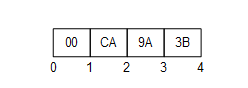
Figure 2 – Encoding Integers in a binary stream
All floating-point values shall be encoded with the appropriate IEEE 754 binary representation which has three basic components: the sign, the exponent, and the fraction. The bit ranges assigned to each component depend on the width of the type. Table 14 lists the bit ranges for the supported floating-point types.
Table 14 – Supported Floating Point Types
|
Name |
Width (bits) |
Fraction |
Exponent |
Sign |
|
Float |
32 |
0-22 |
23-30 |
31 |
|
Double |
64 |
0-51 |
52-62 |
63 |
In addition, the order of bytes in the stream is significant. All floating-point values shall be encoded with the least significant byte appearing first (i.e., little endian).
Figure 3 illustrates how the value −6.5 (Hex: C0D00000) is encoded as a Float.
The floating-point type supports positive and negative infinity and not-a-number (NaN). The IEEE specification allows for multiple NaN variants; however, the encoders/decoders may not preserve the distinction. Encoders shall encode a NaN value as an IEEE quiet-NAN (Hex: 000000000000F8FF) or (Hex: 0000C0FF). Any unsupported types such as denormalized numbers shall also be encoded as an IEEE quiet-NAN. Any test for equality between NaN values always fails.
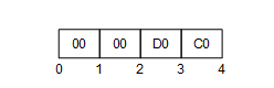
Figure 3 – Encoding Floating Points in a binary stream
All String values are encoded as a sequence of UTF-8 characters preceded by the length in bytes.
The length in bytes is encoded as Int32. A value of −1 is used to indicate a ‘null’ string.
Strings with embedded nulls (‘\0’) can lead to unpredictable application behaviour because embedded nulls have special meaning to some DevelopmentPlatforms. For this reason, embedded nulls are not recommended and ByteString should be used instead. That said, Encoders may encode Strings with embedded nulls. Decoders shall use the length to read all bytes in String.
Figure 4 illustrates how the multilingual string ‘水Boy’ is encoded in a byte stream.
Figure 4 – Encoding Strings in a binary stream
A DateTime value shall be encoded as a 64-bit signed integer (see 5.2.1.2) which represents the number of 100 nanosecond intervals since January 1, 1601 (UTC).
Not all DevelopmentPlatforms will be able to represent the full range of dates and times that can be represented with this DataEncoding. For example, the UNIX time_t structure only has a 1 second resolution and cannot represent dates prior to 1970. For this reason, a number of rules shall be applied when dealing with date/time values that exceed the dynamic range of a DevelopmentPlatform. These rules are:
a) A date/time value is encoded as 0 if either
1) The value is equal to or earlier than 1601-01-01 12:00AM UTC.
2) The value is the earliest date that can be represented with the DevelopmentPlatform’s encoding.
b) A date/time is encoded as the maximum value for an Int64 if either
1) The value is equal to or greater than 9999-12-31 11:59:59PM UTC,
2) The value is the latest date that can be represented with the DevelopmentPlatform’s encoding.
c) A date/time is decoded as the earliest time that can be represented on the platform if either
1) The encoded value is 0,
2) The encoded value represents a time earlier than the earliest time that can be represented with the DevelopmentPlatform’s encoding.
d) A date/time is decoded as the latest time that can be represented on the platform if either
1) The encoded value is the maximum value for an Int64,
2) The encoded value represents a time later than the latest time that can be represented with the DevelopmentPlatform’s encoding.
These rules imply that the earliest and latest times that can be represented on a given platform are invalid date/time values and should be treated that way by applications.
A decoder shall truncate the value if a decoder encounters a DateTime value with a resolution that is greater than the resolution supported on the DevelopmentPlatform.
A Guid is encoded in a structure as shown in Table 2. Fields are encoded sequentially according to the data type for field.
Figure 5 illustrates how the Guid “72962B91-FA75-4AE6-8D28-B404DC7DAF63” is encoded in a byte stream.
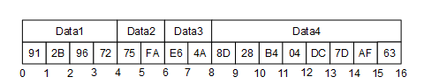
Figure 5 – Encoding Guids in a binary stream
A ByteString is encoded as sequence of bytes preceded by its length in bytes. The length is encoded as a 32-bit signed integer as described above.
If the length of the byte string is −1 then the byte string is ‘null’.
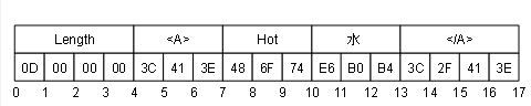
An XmlElement is an XML element serialized as UTF-8 string and then encoded as ByteString.
Figure 6 illustrates how the XmlElement “<A>Hot水</A>” is encoded in a byte stream.
Figure 6 – Encoding XmlElement in a binary stream
The components of a NodeId are described the Table 15.
Table 15 – NodeId components
|
Name |
Data Type |
Description |
|
Namespace |
UInt16 |
The index for a namespace URI. An index of 0 is used for OPC UA defined NodeIds. |
|
IdentifierType |
Enumeration |
The format and data type of the identifier. The value may be one of the following: NUMERIC - the value is an UInteger; STRING - the value is String; GUID - the value is a Guid; OPAQUE - the value is a ByteString; |
|
Value |
UInt32 or String or Guid or ByteString |
The identifier for a node in the address space of an OPC UA Server. |
The DataEncoding of a NodeId varies according to the contents of the instance. For that reason, the first byte of the encoded form indicates the format of the rest of the encoded NodeId. The possible DataEncoding formats are shown in Table 16. Table 16 through Table 19 describe the structure of each possible format (they exclude the byte which indicates the format).
Table 16 – NodeId DataEncoding values
|
Name |
Value |
Description |
|
Two Byte |
0x00 |
A numeric value that fits into the two-byte representation. |
|
Four Byte |
0x01 |
A numeric value that fits into the four-byte representation. |
|
Numeric |
0x02 |
A numeric value that does not fit into the two or four byte representations. |
|
String |
0x03 |
A String value. |
|
Guid |
0x04 |
A Guid value. |
|
ByteString |
0x05 |
An opaque (ByteString) value. |
|
NamespaceUri Flag |
0x80 |
See discussion of ExpandedNodeId in 5.2.1.10. |
|
ServerIndex Flag |
0x40 |
See discussion of ExpandedNodeId in 5.2.1.10. |
The standard NodeId DataEncoding has the structure shown in Table 17. The standard DataEncoding is used for all formats that do not have an explicit format defined.
Table 17 – Standard NodeId Binary DataEncoding
|
Name |
Data Type |
Description |
||||||||
|
Namespace |
UInt16 |
The NamespaceIndex. |
||||||||
|
Identifier |
* |
The identifier which is encoded according to the following rules:
|
An example of a String NodeId with Namespace = 1 and Identifier = “Hot水” is shown in Figure 7.
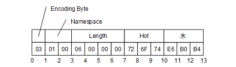
Figure 7 – A String NodeId
The Two Byte NodeId DataEncoding has the structure shown in Table 18.
Table 18 – Two Byte NodeId Binary DataEncoding
|
Name |
Data Type |
Description |
|
Identifier |
Byte |
The Namespace is the default OPC UA namespace (i.e. 0). The Identifier Type is ‘Numeric’. The Identifier shall be in the range 0 to 255. |
An example of a Two Byte NodeId with Identifier = 72 is shown in Figure 8.

Figure 8 – A Two Byte NodeId
The Four Byte NodeId DataEncoding has the structure shown in Table 19.
Table 19 – Four Byte NodeId Binary DataEncoding
|
Name |
Data Type |
Description |
|
Namespace |
Byte |
The Namespace shall be in the range 0 to 255. |
|
Identifier |
UInt16 |
The Identifier Type is ‘Numeric’. The Identifier shall be an integer in the range 0 to 65 535. |
An example of a Four Byte NodeId with Namespace = 5 and Identifier = 1025 is shown in Figure 9.
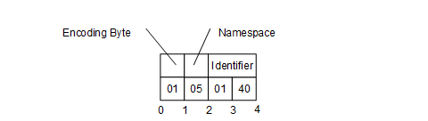
Figure 9 – A Four Byte NodeId
An ExpandedNodeId extends the NodeId structure by allowing the NamespaceUri to be explicitly specified instead of using the NamespaceIndex. The NamespaceUri is optional. If it is specified, then the NamespaceIndex inside the NodeId shall be ignored.
The ExpandedNodeId is encoded by first encoding a NodeId as described in 5.2.1.9 and then encoding NamespaceUri as a String.
An instance of an ExpandedNodeId may still use the NamespaceIndex instead of the NamespaceUri. In this case, the NamespaceUri is not encoded in the stream. The presence of the NamespaceUri in the stream is indicated by setting the NamespaceUri flag in the encoding format byte for the NodeId.
If the NamespaceUri is present, then the encoder shall encode the NamespaceIndex as 0 in the stream when the NodeId portion is encoded. The unused NamespaceIndex is included in the stream for consistency.
An ExpandedNodeId may also have a ServerIndex which is encoded as a UInt32 after the NamespaceUri. The ServerIndex flag in the NodeId encoding byte indicates whether the ServerIndex is present in the stream. The ServerIndex is omitted if it is equal to zero.
The ExpandedNodeId encoding has the structure shown in Table 20.
Table 20 – ExpandedNodeId Binary DataEncoding
|
Name |
Data Type |
Description |
|
NodeId |
NodeId |
The NamespaceUri and ServerIndex flags in the NodeId encoding indicate whether those fields are present in the stream. |
|
NamespaceUri |
String |
Not present if null or Empty. |
|
ServerIndex |
UInt32 |
Not present if 0. |
A StatusCode is encoded as a UInt32.
A DiagnosticInfo structure is described in OPC 10000-4. It specifies a number of fields that could be missing. For that reason, the encoding uses a bit mask to indicate which fields are actually present in the encoded form.
As described in OPC 10000-4, the SymbolicId, NamespaceUri, LocalizedText and Locale fields are indexes in a string table which is returned in the response header. Only the index of the corresponding string in the string table is encoded. An index of −1 indicates that there is no value for the string.
DiagnosticInfo is recursive and unlimited recursion could result in stack overflow errors even if the message size is less than the maximum allowed. Decoders shall support at least 4 recursion levels and are not expected to support more than 10. Decoders shall report an error if the number of recursion levels exceeds what it supports.
Table 21 – DiagnosticInfo Binary DataEncoding
|
Name |
Data Type |
Description |
||||||||||||||
|
Encoding Mask |
Byte |
A bit mask that indicates which fields are present in the stream. The mask has the following bits:
|
||||||||||||||
|
SymbolicId |
Int32 |
A symbolic name for the status code. |
||||||||||||||
|
NamespaceUri |
Int32 |
A namespace that qualifies the symbolic id. |
||||||||||||||
|
Locale |
Int32 |
The locale used for the localized text. |
||||||||||||||
|
LocalizedText |
Int32 |
A human readable summary of the status code. |
||||||||||||||
|
Additional Info |
String |
Detailed application specific diagnostic information. |
||||||||||||||
|
Inner StatusCode |
StatusCode |
A status code provided by an underlying system. |
||||||||||||||
|
Inner DiagnosticInfo |
DiagnosticInfo |
Diagnostic info associated with the inner status code. |
A QualifiedName structure is encoded as shown in Table 22.
The abstract QualifiedName structure is defined in OPC 10000-3.
Table 22 – QualifiedName Binary DataEncoding
|
Name |
Data Type |
Description |
|
NamespaceIndex |
UInt16 |
The namespace index. |
|
Name |
String |
The name. |
A LocalizedText structure contains two fields that could be missing. For that reason, the encoding uses a bit mask to indicate which fields are actually present in the encoded form.
The abstract LocalizedText structure is defined in OPC 10000-3.
Table 23 – LocalizedText Binary DataEncoding
|
Name |
Data Type |
Description |
||||
|
EncodingMask |
Byte |
A bit mask that indicates which fields are present in the stream. The mask has the following bits:
|
||||
|
Locale |
String |
The locale. Omitted is null or empty. |
||||
|
Text |
String |
The text in the specified locale. Omitted is null or empty. |
An ExtensionObject is encoded as sequence of bytes prefixed by the NodeId of its DataTypeEncoding, the DataEncoding used and the number of bytes encoded.
An ExtensionObject may be serialized as a ByteString or an XmlElement by the application and then passed to the encoder. In this case, the encoder will be able to write the number of bytes in the object before it encodes the bytes. However, an ExtensionObject may know how to encode/decode itself which means the encoder shall calculate the number of bytes before it encodes the object or it shall be able to seek backwards in the stream and update the length after encoding the body.
When a decoder encounters an ExtensionObject it shall check if it recognizes the DataTypeEncoding identifier. If it does, then it can call the appropriate function to decode the object body. If the decoder does not recognize the type it shall use the Encoding to determine if the body is a ByteString or an XmlElement and then decode the object body or treat it as opaque data and skip over it.
If the Encoding is Binary the Body uses the OPC UA Binary DataEncoding. If the Encoding is XML the Body uses the OPC UA XML DataEncoding. Other DataEncodings may not be serialized in an ExtensionObject.
The serialized form of an ExtensionObject is shown in Table 24.
Table 24 – Extension Object Binary DataEncoding
|
Name |
Data Type |
Description |
||||||
|
TypeId |
NodeId |
The identifier for the DataTypeEncoding node in the Server's AddressSpace. ExtensionObjects defined by the OPC UA specification have a numeric node identifier assigned to them with a NamespaceIndex of 0. The numeric identifiers are defined in A.3. Decoders use this field to determine the syntax of the Body. |
||||||
|
Encoding |
Byte |
An enumeration that indicates how the body is encoded. The parameter may have the following values:
|
||||||
|
Length |
Int32 |
The length of the object body. The length shall be specified if the body is encoded. |
||||||
|
Body |
OctetString |
The object encoded with the DataEncoding indicated by the TypeId. This field contains the raw bytes for ByteString bodies. For XmlElement bodies this field contains the XML encoded as a UTF-8 string without any null terminator. |
A decoder may choose to parse an XmlElement body after decoding; if an unrecoverable parsing error occurs then the decoder should try to continue processing the stream. For example, if the ExtensionObject is the body of a Variant or an element in an array that is the body of Variant then this error can be reported by setting the value of the Variant to the StatusCode Bad_DecodingError.
A Variant is a union of the built-in types.
The structure of a Variant is shown in Table 25.
Table 25 – Variant Binary DataEncoding
|
Name |
Data Type |
Description |
||||||
|
EncodingMask |
Byte |
The type of data encoded in the stream.
The Built-in Type Ids 26 through 31 are not currently assigned but may be used in the future. Decoders shall accept these IDs, assume the Value contains a ByteString or an array of ByteStrings and pass both onto the application. Encoders shall not use these IDs. The ArrayDimensions field shall only be present if the number of dimensions is 2 or greater and all dimensions have a length greater than 0. |
||||||
|
ArrayLength |
Int32 |
The number of elements in the array. This field is only present if the array bit is set in the encoding mask. Multi-dimensional arrays are encoded as a one-dimensional array and this field specifies the total number of elements. The original array can be reconstructed from the dimensions that are encoded after the value field. Higher rank dimensions are serialized first. For example, an array with dimensions [2,2,2] is written in this order: [0,0,0], [0,0,1], [0,1,0], [0,1,1], [1,0,0], [1,0,1], [1,1,0], [1,1,1] If one or more dimensions has a length <= 0 then the ArrayLength is 0. |
||||||
|
Value |
* |
The value encoded according to its built-in data type. If the array bit is set in the encoding mask, then each element in the array is encoded sequentially. Since many types have variable length encoding each element shall be decoded in order. The value shall not be a Variant but it could be an array of Variants. Many implementation platforms do not distinguish between one dimensional Arrays of Bytes and ByteStrings. For this reason, decoders are allowed to automatically convert an Array of Bytes to a ByteString. |
||||||
|
ArrayDimensions |
Int32 |
The number of dimensions. This field is only present if the ArrayDimensions flag is set in the encoding mask. |
||||||
|
ArrayDimensions |
Int32[] |
The length of each dimension encoded as a sequence of Int32 values This field is only present if the ArrayDimensions flag is set in the encoding mask. The lower rank dimensions appear first in the array. All dimensions shall be specified and shall be greater than zero.. If ArrayDimensions are inconsistent with the ArrayLength then the decoder shall stop and raise a Bad_DecodingError. |
The types and their identifiers that can be encoded in a Variant are shown in Table 1.
A DataValue is always preceded by a mask that indicates which fields are present in the stream.
The fields of a DataValue are described in Table 26.
Table 26 – Data Value Binary DataEncoding
|
Name |
Data Type |
Description |
||||||||||||
|
Encoding Mask |
Byte |
A bit mask that indicates which fields are present in the stream. The mask has the following bits:
|
||||||||||||
|
Value |
Variant |
The value. Not present if the Value bit in the EncodingMask is False. |
||||||||||||
|
Status |
StatusCode |
The status associated with the value. Not present if the StatusCode bit in the EncodingMask is False. |
||||||||||||
|
SourceTimestamp |
DateTime |
The source timestamp associated with the value. Not present if the SourceTimestamp bit in the EncodingMask is False. |
||||||||||||
|
SourcePicoseconds |
UInt16 |
The number of 10 Picosecond intervals for the SourceTimestamp. Not present if the SourcePicoseconds bit in the EncodingMask is False. If the source timestamp is missing the Picoseconds are ignored. |
||||||||||||
|
ServerTimestamp |
DateTime |
The Server timestamp associated with the value. Not present if the ServerTimestamp bit in the EncodingMask is False. |
||||||||||||
|
ServerPicoseconds |
UInt16 |
The number of 10 Picosecond intervals for the ServerTimestamp. Not present if the ServerPicoseconds bit in the EncodingMask is False. If the Server timestamp is missing the Picoseconds are ignored. |
The Picoseconds fields store the difference between a high-resolution timestamp with a resolution of 10 Picoseconds and the Timestamp field value which only has a 100 ns resolution. The Picoseconds fields shall contain values less than 10 000. The decoder shall treat values greater than or equal to 10 000 as the value ‘9999’.
Decimals are encoded as described in 1.1.7.
A Decimal does not have a NULL value.
Enumerations are encoded as Int32 values.
An Enumeration does not have a NULL value.
One dimensional Arrays are encoded as a sequence of elements preceded by the number of elements encoded as an Int32 value.
Multi-dimensional Arrays have an encoding that depends on where they are used. When a multi-dimensional Array is the Value of an Attribute it uses the Variant encoding described in 5.2.1.16.
When a multi-dimensional Array is a field of a Structure (see 1.1.15) it shall be encoded with the inline matrix representation as shown in Table 27.
Table 27 – Inline Matrix DataEncoding
|
Name |
Data Type |
Description |
|
Dimensions |
Int32 [] |
The length of each dimension. If any dimension has a length <= 0, then no values are encoded. The number of dimensions shall be at least 2. |
|
Values |
* |
The values encoded sequentially according to its built-in data type. The total number of values is the product of the dimensions. The mapping of a multidimensional array to a flat list is described in 5.2.1.16. |
The inline matrix representation is not supported by earlier versions of this specification. This means any Structure with a field or nested field mapped to an inline matrix is not compatible with the deprecated DataTypeDictionary mechanism, and shall not be included in a DataTypeDictionary.
If an Array is null, then its length is encoded as −1. See 1.1.8 for a discussion of zero-length vs null arrays.
Structures are encoded as a sequence of fields in the order that they appear in the definition. The encoding for each field is determined by the built-in type for the field.
All fields specified in the structure shall be encoded. If optional fields exist in the Structure, then see 1.1.16.
Structures do not have a null value. If an encoder is written in a programming language that allows structures to have null values, then the encoder shall create a new instance with DefaultValues for all fields and serialize that. Encoders shall not generate an encoding error in this situation.
The following is an example of a structure using C/C++ syntax:
struct Type2
{
Int32 A;
Int32 B;
};
struct Type1
{
Int32 X;
Byte NoOfY;
Type2* Y;
Int32 Z;
UInt16 W[10];
Byte M[2,3,4];
};
In the C/C++ example above, the Y field is a pointer to an array with a length stored in NoOfY. When encoding an array, the length is part of the array encoding so the NoOfY field is not encoded. That said, encoders and decoders use NoOfY during encoding. W is a fixed length array with an implicitly defined length of 10. This length is always encoded with the array. M is a fixed length multidimensional array. The length of each dimension is always encoded with the array.
An instance of Type1 which contains an array of two Type2 instances would be encoded as 28-byte sequence. If the instance of Type1 was encoded in an ExtensionObject it would have an additional prefix shown in Table 28 which would make the total length 101 bytes The TypeId, Encoding and the Length are fields defined by the ExtensionObject. The encoding of the Type2 instances do not include any type identifier because it is explicitly defined in Type1.
Table 28 – Sample OPC UA Binary Encoded structure
|
Field |
Bytes |
Value |
|
Type Id |
4 |
|
|
Encoding |
1 |
0x1 for ByteString |
|
Length |
4 |
28 |
|
X |
4 |
The value of field ‘X’ |
|
Y.Length |
4 |
2 |
|
Y.A |
4 |
The value of field ‘Y[0].A’ |
|
Y.B |
4 |
The value of field ‘Y[0].B’ |
|
Y.A |
4 |
The value of field ‘Y[1].A’ |
|
Y.B |
4 |
The value of field ‘Y[1].B’ |
|
Z |
4 |
The value of field ‘Z’ |
|
W.Length |
4 |
10 |
|
W |
20 |
The value of field ‘W’. |
|
M.Dimensions.Length |
4 |
3 |
|
M.Dimensions |
12 |
The sequence [2,3,4] encoded as a Int32. |
|
M.Values |
24 |
The values in ‘M’ encoded sequentially as described in 5.2.1.16. |
The Value of the DataTypeDefinition Attribute for a DataType Node describing Type1 is shown in Table 29.
Table 29 – DataTypeDefinition for “Type1” from Sample
|
Name |
Type |
Description |
|
defaultEncodingId |
NodeId |
NodeId of the “Type1_Encoding_DefaultBinary” Node. |
|
baseDataType |
NodeId |
“i=22” [Structure] |
|
structureType |
StructureType |
Structure_0 [Structure without optional fields] |
|
fields [0] |
StructureField |
|
|
name |
String |
“X” |
|
description |
LocalizedText |
Description of X |
|
dataType |
NodeId |
“i=6” [Int32] |
|
valueRank |
Int32 |
-1 (Scalar) |
|
arrayDimensions |
UInt32[] |
null |
|
maxStringLength |
UInt32 |
0 |
|
isOptional |
Boolean |
false |
|
fields [1] |
StructureField |
|
|
name |
String |
“Y“ |
|
description |
LocalizedText |
Description of Y-Array |
|
dataType |
NodeId |
NodeId of the Type2 DataType Node (e.g. “ns=3; s=MyType2”) |
|
valueRank |
Int32 |
1 (OneDimension) |
|
arrayDimensions |
UInt32[] |
{ 0 } |
|
maxStringLength |
UInt32 |
0 |
|
isOptional |
Boolean |
false |
|
fields [2] |
StructureField |
|
|
name |
String |
“Z“ |
|
description |
LocalizedText |
Description of Z |
|
dataType |
NodeId |
“i=6” [Int32] |
|
valueRank |
Int32 |
-1 (Scalar) |
|
arrayDimensions |
UInt32[] |
null |
|
maxStringLength |
UInt32 |
0 |
|
isOptional |
Boolean |
false |
|
fields [3] |
StructureField |
|
|
name |
String |
“W“ |
|
description |
LocalizedText |
Description of W |
|
dataType |
NodeId |
“i=5” [UInt16] |
|
valueRank |
Int32 |
1 (OneDimension) |
|
arrayDimensions |
UInt32[] |
{ 10 } |
|
maxStringLength |
UInt32 |
0 |
|
isOptional |
Boolean |
false |
|
fields [4] |
StructureField |
|
|
name |
String |
“M“ |
|
description |
LocalizedText |
Description of M |
|
dataType |
NodeId |
“i=3” [Byte] |
|
valueRank |
Int32 |
3 |
|
arrayDimensions |
UInt32[] |
{ 2, 3, 4 } |
|
maxStringLength |
UInt32 |
0 |
|
isOptional |
Boolean |
false |
The Value of the DataTypeDefinition Attribute for a DataType Node describing Type2 is shown in Table 30.
Table 30 – DataTypeDefinition for “Type2” from Sample
|
Name |
Type |
Description |
|
defaultEncodingId |
NodeId |
NodeId of the “Type2_Encoding_DefaultBinary” Node. |
|
baseDataType |
NodeId |
“i=22” [Structure] |
|
structureType |
StructureType |
Structure_0 [Structure without optional fields] |
|
fields [0] |
StructureField |
|
|
name |
String |
“A“ |
|
description |
LocalizedText |
Description of A |
|
dataType |
NodeId |
“i=6” [Int32] |
|
valueRank |
Int32 |
-1 (Scalar) |
|
arrayDimensions |
UInt32[] |
null |
|
maxStringLength |
UInt32 |
0 |
|
isOptional |
Boolean |
false |
|
fields [1] |
StructureField |
|
|
name |
String |
“B“ |
|
description |
LocalizedText |
Description of B |
|
dataType |
NodeId |
“i=6” [Int32] |
|
valueRank |
Int32 |
-1 (Scalar) |
|
arrayDimensions |
UInt32[] |
null |
|
maxStringLength |
UInt32 |
0 |
|
isOptional |
Boolean |
false |
Structures with optional fields are encoded with an encoding mask preceding a sequence of fields in the order that they appear in the definition. The encoding for each field is determined by the data type for the field.
The EncodingMask is a 32-bit unsigned integer. Each optional field is assigned exactly one bit. The first optional field is assigned bit ‘0’, the second optional field is assigned bit ‘1’ and so until all optional fields are assigned bits. A maximum of 32 optional fields can appear within a single Structure. Unassigned bits are set to 0 by encoders. Decoders shall report an error if unassigned bits are not 0.
The following is an example of a structure with optional fields using C++ syntax:
struct TypeA
{
Int32 X;
Int32* O1;
SByte Y;
Int32* O2;
};
O1 and O2 are optional fields which are NULL if not present
An instance of TypeA which contains two mandatory (X and Y) and two optional (O1 and O2) fields would be encoded as a byte sequence. The length of the byte sequence depends on the available optional fields. An encoding mask field determines the available optional fields.
An instance of TypeA where field O2 is available and field O1 is not available would be encoded as a 13-byte sequence. If the instance of TypeA was encoded in an ExtensionObject it would have the encoded form shown in Table 31 and have a total length of 22 bytes. The length of the TypeId, Encoding and the Length are fields defined by the ExtensionObject.
Table 31 – Sample OPC UA Binary Encoded Structure with optional fields
|
Field |
Bytes |
Value |
|
Type Id |
4 |
The identifier for the TypeA Binary Encoding Node |
|
Encoding |
1 |
0x1 for ByteString |
|
Length |
4 |
13 |
|
EncodingMask |
4 |
0x02 for O2 |
|
X |
4 |
The value of X |
|
Y |
1 |
The value of Y |
|
O2 |
4 |
The value of O2 |
If a Structure with optional fields is subtyped, the subtypes extend the EncodingMask defined for the parent.
The Value of the DataTypeDefinition Attribute for a DataType Node describing TypeA is:
|
Name |
Type |
Description |
|
defaultEncodingId |
NodeId |
NodeId of the “TypeA_Encoding_DefaultBinary” Node. |
|
baseDataType |
NodeId |
“i=22” [Structure] |
|
structureType |
StructureType |
StructureWithOptionalFields_1 [Structure without optional fields] |
|
fields [0] |
StructureField |
|
|
name |
String |
“X” |
|
description |
LocalizedText |
Description of X |
|
dataType |
NodeId |
“i=6” [Int32] |
|
valueRank |
Int32 |
-1 (Scalar) |
|
arrayDimensions |
UInt32[] |
null |
|
maxStringLength |
UInt32 |
0 |
|
isOptional |
Boolean |
false |
|
fields [1] |
StructureField |
|
|
name |
String |
“O1“ |
|
description |
LocalizedText |
Description of O1 |
|
dataType |
NodeId |
“i=6” [Int32] |
|
valueRank |
Int32 |
-1 (Scalar) |
|
arrayDimensions |
UInt32[] |
null |
|
maxStringLength |
UInt32 |
0 |
|
isOptional |
Boolean |
true |
|
fields [2] |
StructureField |
|
|
name |
String |
“Y“ |
|
description |
LocalizedText |
Description of Z |
|
dataType |
NodeId |
“i=2” [SByte] |
|
valueRank |
Int32 |
-1 (Scalar) |
|
arrayDimensions |
UInt32[] |
null |
|
maxStringLength |
UInt32 |
0 |
|
isOptional |
Boolean |
false |
|
fields [3] |
StructureField |
|
|
name |
String |
“O2“ |
|
description |
LocalizedText |
Description of O2 |
|
dataType |
NodeId |
“i=6” [Int32] |
|
valueRank |
Int32 |
-1 (Scalar) |
|
arrayDimensions |
UInt32[] |
null |
|
maxStringLength |
UInt32 |
0 |
|
isOptional |
Boolean |
true |
Unions are encoded as a switch field preceding one of the possible fields. The encoding for the selected field is determined by the data type for the field.
The switch field is encoded as a UInt32.
The switch field is the index of the available union fields starting with 1. If the switch field is 0 then no field is present. For any value greater than the number of defined union fields the encoders or decoders shall report an error.
A Union with no fields present has the same meaning as a NULL value. A Union with any field present is not a NULL value even if the value of the field itself is NULL.
The following is an example of a union using C/C++ syntax:
struct Type2
{
Int32 A;
Int32 B;
};
struct Type1
{
Byte Selector;
union
{
Int32 Field1;
Type2 Field2;
}
Value;
};
In the C/C++ example above, the Selector, Field1 and Field2 are semantically coupled to form a union.
An instance of Type1 would be encoded as byte sequence. The length of the byte sequence depends on the selected field.
An instance of Type1 where field Field1 is available would be encoded as 8-byte sequence. If the instance of Type 1 was encoded in an ExtensionObject it would have the encoded form shown in Table 32 and it would have a total length of 17 bytes. The TypeId, Encoding and the Length are fields defined by the ExtensionObject.
Table 32 – Sample OPC UA Binary Encoded Structure
|
Field |
Bytes |
Value |
|
Type Id |
4 |
The identifier for Type1 |
|
Encoding |
1 |
0x1 for ByteString |
|
Length |
4 |
8 |
|
SwitchValue |
4 |
1 for Field1 |
|
Field1 |
4 |
The value of Field1 |
The Value of the DataTypeDefinition Attribute for a DataType Node describing Type1 is:
|
Name |
Type |
Description |
|
defaultEncodingId |
NodeId |
NodeId of the “Type1_Encoding_DefaultBinary” Node. |
|
baseDataType |
NodeId |
“i=22” [Union] |
|
structureType |
StructureType |
Union_2 [Union] |
|
fields [0] |
StructureField |
|
|
name |
String |
“Field1” |
|
description |
LocalizedText |
Description of Field1 |
|
dataType |
NodeId |
“i=6” [Int32] |
|
valueRank |
Int32 |
-1 (Scalar) |
|
arrayDimensions |
UInt32[] |
null |
|
maxStringLength |
UInt32 |
0 |
|
isOptional |
Boolean |
true |
|
fields [1] |
StructureField |
|
|
name |
String |
“Field2“ |
|
description |
LocalizedText |
Description of Field2 |
|
dataType |
NodeId |
NodeId of the Type2 DataType Node (e.g. “ns=3; s=MyType2”) |
|
valueRank |
Int32 |
-1 (Scalar) |
|
arrayDimensions |
UInt32[] |
null |
|
maxStringLength |
UInt32 |
0 |
|
isOptional |
Boolean |
true |
The Value of the DataTypeDefinition Attribute for a DataType Node describing Type2 is:
|
Name |
Type |
Description |
|
defaultEncodingId |
NodeId |
NodeId of the “Type2_Encoding_DefaultBinary” Node. |
|
baseDataType |
NodeId |
“i=22” [Structure] |
|
structureType |
StructureType |
Structure_0 [Structure without optional fields] |
|
fields [0] |
StructureField |
|
|
name |
String |
“A“ |
|
description |
LocalizedText |
Description of A |
|
dataType |
NodeId |
“i=6” [Int32] |
|
valueRank |
Int32 |
-1 (Scalar) |
|
arrayDimensions |
UInt32[] |
null |
|
maxStringLength |
UInt32 |
0 |
|
isOptional |
Boolean |
false |
|
fields [1] |
StructureField |
|
|
name |
String |
“B“ |
|
description |
LocalizedText |
Description of B |
|
dataType |
NodeId |
“i=6” [Int32] |
|
valueRank |
Int32 |
-1 (Scalar) |
|
arrayDimensions |
UInt32[] |
null |
|
maxStringLength |
UInt32 |
0 |
|
isOptional |
Boolean |
false |
Messages are Structures encoded as sequence of bytes prefixed by the NodeId of for the OPC UA Binary DataTypeEncoding defined for the Message.
Each OPC UA Service described in OPC 10000-4 has a request and response Message. The DataTypeEncoding IDs assigned to each Service are specified in Clause A.3.
Most built-in types are encoded in XML using the formats defined in XML Schema Part 2 specification. Any special restrictions or usages are discussed below. Some of the built-in types have an XML Schema defined for them using the syntax defined in XML Schema Part 2.
The prefix xs: is used to denote a symbol defined by the XML Schema specification.
A Boolean value is encoded as an xs:boolean value.
Integer values are encoded using one of the subtypes of the xs:decimal type. The mappings between the OPC UA integer types and XML schema data types are shown in Table 33.
Table 33 – XML Data Type Mappings for Integers
|
Name |
XML Type |
|
SByte |
xs:byte |
|
Byte |
xs:unsignedByte |
|
Int16 |
xs:short |
|
UInt16 |
xs:unsignedShort |
|
Int32 |
xs:int |
|
UInt32 |
xs:unsignedInt |
|
Int64 |
xs:long |
|
UInt64 |
xs:unsignedLong |
Floating point values are encoded using one of the XML floating point types. The mappings between the OPC UA floating point types and XML schema data types are shown in Table 34.
Table 34 – XML Data Type Mappings for Floating Points
|
Name |
XML Type |
|
Float |
xs:float |
|
Double |
xs:double |
The XML floating point type supports positive infinity (INF), negative infinity (-INF) and not-a-number (NaN).
A String value is encoded as an xs:string value.
A DateTime value is encoded as an xs:dateTime value.
All DateTime values shall be encoded as UTC times or with the time zone explicitly specified.
Correct:
2002-10-10T00:00:00+05:00
2002-10-09T19:00:00Z
Incorrect:
2002-10-09T19:00:00
It is recommended that all xs:dateTime values be represented in UTC format.
The earliest and latest date/time values that can be represented on a DevelopmentPlatform have special meaning and shall not be literally encoded in XML.
The earliest date/time value on a DevelopmentPlatform shall be encoded in XML as '0001-01-01T00:00:00Z'.
The latest date/time value on a DevelopmentPlatform shall be encoded in XML as '9999-12-31T23:59:59Z'
If a decoder encounters a xs:dateTime value that cannot be represented on the DevelopmentPlatform it should convert the value to either the earliest or latest date/time that can be represented on the DevelopmentPlatform. The XML decoder should not generate an error if it encounters an out of range date value.
The earliest date/time value on a DevelopmentPlatform is equivalent to a null date/time value.
A Guid is encoded using the string representation defined in 1.1.3.
The XML schema for a Guid is:
<xs:complexType name="Guid">
<xs:sequence>
<xs:element name="String" type="xs:string" minOccurs="0" />
</xs:sequence>
</xs:complexType>
A ByteString value is encoded as an xs:base64Binary value (see Base64).
The XML schema for a ByteString is:
<xs:element name="ByteString" type="xs:base64Binary" nillable="true"/>
An XmlElement value is encoded as an xs:complexType with the following XML schema:
<xs:complexType name="XmlElement">
<xs:sequence>
<xs:any minOccurs="0" maxOccurs="1" processContents="lax" />
</xs:sequence>
</xs:complexType>
XmlElements may only be used inside Variant or ExtensionObject values.
A NodeId value is encoded as an xs:string with the syntax defined in 1.1.9.
The XML schema for a NodeId is:
<xs:complexType name="NodeId">
<xs:sequence>
<xs:element name="Identifier" type="xs:string" minOccurs="0" />
</xs:sequence>
</xs:complexType>
An ExpandedNodeId value is encoded as an xs:string with the syntax defined in 1.1.9.
The XML schema for an ExpandedNodeId is:
<xs:complexType name="ExpandedNodeId">
<xs:sequence>
<xs:element name="Identifier" type="xs:string" minOccurs="0" />
</xs:sequence>
</xs:complexType>
A StatusCode is encoded as an xs:unsignedInt with the following XML schema:
<xs:complexType name="StatusCode">
<xs:sequence>
<xs:element name="Code" type="xs:unsignedInt" minOccurs="0" />
</xs:sequence>
</xs:complexType>
An DiagnosticInfo value is encoded as an xs:complexType with the following XML schema:
<xs:complexType name="DiagnosticInfo">
<xs:sequence>
<xs:element name="SymbolicId" type="xs:int" minOccurs="0" />
<xs:element name="NamespaceUri" type="xs:int" minOccurs="0" />
<xs:element name="Locale" type="xs:int" minOccurs="0/>
<xs:element name="LocalizedText" type="xs:int" minOccurs="0/>
<xs:element name="AdditionalInfo" type="xs:string" minOccurs="0"/>
<xs:element name="InnerStatusCode" type="tns:StatusCode"
minOccurs="0" />
<xs:element name="InnerDiagnosticInfo" type="tns:DiagnosticInfo"
minOccurs="0" />
</xs:sequence>
</xs:complexType>
DiagnosticInfo is recursive and unlimited recursion could result in stack overflow errors even if the message size is less than the maximum allowed. Decoders shall support at least 4 recursion levels and are not expected to support more than 10. Decoders shall report an error if the number of recursion levels exceeds what it supports.
A QualifiedName value is encoded as an xs:complexType with the following XML schema:
<xs:complexType name="QualifiedName">
<xs:sequence>
<xs:element name="NamespaceIndex" type="xs:int" minOccurs="0" />
<xs:element name="Name" type="xs:string" minOccurs="0" />
</xs:sequence>
</xs:complexType>
A LocalizedText value is encoded as an xs:complexType with the following XML schema:
<xs:complexType name="LocalizedText">
<xs:sequence>
<xs:element name="Locale" type="xs:string" minOccurs="0" />
<xs:element name="Text" type="xs:string" minOccurs="0" />
</xs:sequence>
</xs:complexType>
An ExtensionObject value is encoded as an xs:complexType with the following XML schema:
<xs:complexType name="ExtensionObject">
<xs:sequence>
<xs:element name="TypeId" type="tns:NodeId" minOccurs="0" />
<xs:element name="Body" minOccurs="0">
<xs:complexType>
<xs:sequence>
<xs:any minOccurs="0" processContents="lax"/>
</xs:sequence>
</xs:complexType>
</xs:element>
</xs:sequence>
</xs:complexType>
The body of the ExtensionObject contains a single element which is either a ByteString or XML encoded Structure. A decoder can distinguish between the two by inspecting the top-level element. An XML element with the name tns:ByteString contains an OPC UA Binary encoded body. Any other XML element name shall contain an OPC UA XML encoded body. Other DataEncodings may not be serialized in an ExtensionObject.
The TypeId should be the NodeId for the DataTypeEncoding Node. The NodeId of DataType Node may also be used when the body is encoded with the XML encoding.
A Variant value is encoded as an xs:complexType with the following XML schema:
<xs:complexType name="Variant">
<xs:sequence>
<xs:element name="Value" minOccurs="0" nillable="true">
<xs:complexType>
<xs:sequence>
<xs:any minOccurs="0" processContents="lax"/>
</xs:sequence>
</xs:complexType>
</xs:element>
</xs:sequence>
</xs:complexType>
If the Variant represents a scalar value, then it shall contain a single child element with the name of the built-in type. For example, the single precision floating point value 3.1415 would be encoded as:
<tns:Float>3.1415</tns:Float>
If the Variant represents a single dimensional array, then it shall contain a single child element with the prefix 'ListOf' and the name built-in type. For example, an Array of strings would be encoded as:
<tns:ListOfString>
<tns:String>Hello</tns:String>
<tns:String>World</tns:String>
</tns:ListOfString>
If the Variant represents a multidimensional Array, then it shall contain a child element with the name ‘Matrix’ with the two sub-elements shown in this example:
<tns:Matrix>
<tns:Dimensions>
<tns:Int32>2</tns:Int32>
<tns:Int32>2</tns:Int32>
</tns:Dimensions>
<tns:Elements>
<tns:String>A</tns:String>
<tns:String>B</tns:String>
<tns:String>C</tns:String>
<tns:String>D</tns:String>
</tns:Elements>
</tns:Matrix>
In this example, the array has the following elements:
[0,0] = "A"; [0,1] = "B"; [1,0] = "C"; [1,1] =
"D"
The elements of a multi-dimensional Array are always flattened into a single dimensional Array where the higher rank dimensions are serialized first. This single dimensional Array is encoded as a child of the ‘Elements’ element. The ‘Dimensions’ element is an Array of Int32 values that specify the dimensions of the array starting with the lowest rank dimension. The multi-dimensional Array can be reconstructed by using the dimensions encoded. All dimensions shall be specified and shall be greater than zero. If the dimensions are inconsistent with the number of elements in the array, then the decoder shall stop and raise a Bad_DecodingError.
The complete set of built-in type names is found in Table 1.
A DataValue value is encoded as a xs:complexType with the following XML schema:
<xs:complexType name="DataValue">
<xs:sequence>
<xs:element name="Value" type="tns:Variant" minOccurs="0"
nillable="true" />
<xs:element name="StatusCode" type="tns:StatusCode"
minOccurs="0" />
<xs:element name="SourceTimestamp" type="xs:dateTime"
minOccurs="0" />
<xs:element name="SourcePicoseconds" type="xs:unsignedShort"
minOccurs="0"/>
<xs:element name="ServerTimestamp" type="xs:dateTime"
minOccurs="0" />
<xs:element name="ServerPicoseconds" type="xs:unsignedShort"
minOccurs="0"/>
</xs:sequence>
</xs:complexType>
The subtypes of the built-in DataTypes described in 1.1.19 are encoded as the base Built-in DataType.
A Decimal Value is a encoded as an xs:complexType with the following XML schema:
<xs:complexType name="Decimal">
<xs:sequence>
<xs:element name="TypeId" type="tns:NodeId" minOccurs="0" />
<xs:element name="Body" minOccurs="0">
<xs:complexType>
<xs:sequence>
<xs:element name="Scale" type="xs:short" />
<xs:element name="Value" type="xs:string" />
</xs:sequence>
</xs:complexType>
</xs:element>
</xs:sequence>
</xs:complexType>
The NodeId is always the NodeId of the Decimal DataType. When encoded in a Variant the Decimal is encoded as an ExtensionObject. Arrays of Decimals are Arrays of ExtensionObjects.
The Value is a base-10 signed integer with no limit on size. See 1.1.7 for a description of the Scale and Value fields.
Enumerations that are used as parameters in the Messages defined in OPC 10000-4 are encoded as xs:string with the following syntax:
<symbol>_<value>
The elements of the syntax are described in Table 35.
Table 35 – Components of Enumeration
|
Field |
Type |
Description |
|
<symbol> |
String |
The symbolic name for the enumerated value. |
|
<value> |
UInt32 |
The numeric value associated with enumerated value. |
For example, the XML schema for the NodeClass enumeration is:
<xs:simpleType name="NodeClass">
<xs:restriction base="xs:string">
<xs:enumeration value="Unspecified_0" />
<xs:enumeration value="Object_1" />
<xs:enumeration value="Variable_2" />
<xs:enumeration value="Method_4" />
<xs:enumeration value="ObjectType_8" />
<xs:enumeration value="VariableType_16" />
<xs:enumeration value="ReferenceType_32" />
<xs:enumeration value="DataType_64" />
<xs:enumeration value="View_128" />
</xs:restriction>
</xs:simpleType>
Enumerations that are stored in a Variant are encoded as an Int32 value.
For example, any Variable could have a value with a DataType of NodeClass. In this case, the corresponding numeric value is placed in the Variant (e.g. NodeClass Object would be stored as a 1).
One dimensional Array parameters are always encoded by wrapping the elements in a container element and inserting the container into the structure. The name of the container element should be the name of the parameter. The name of the element in the array shall be the type name.
For example, the Read service takes an array of ReadValueIds. The XML schema would look like:
<xs:complexType name="ListOfReadValueId">
<xs:sequence>
<xs:element name="ReadValueId" type="tns:ReadValueId"
minOccurs="0" maxOccurs="unbounded" nillable="true" />
</xs:sequence>
</xs:complexType>
The nillable attribute shall be specified because XML encoders will drop elements in arrays if those elements are empty.
Multi-dimensional Array parameters are encoded using the Matrix type defined in 5.3.1.17.
Structures are encoded as a xs:complexType with all of the fields appearing as a sequence of xs:elements. Each element has a name specified by the name of the field in the DataTypeDefinition. All elements have minOccurs set 0 to allow for compact XML representations. If an element is missing the DefaultValue for the field type is used. If the field type is a structure the DefaultValue is an instance of the structure with DefaultValues for each contained field.
The XML type for an element name is xs:name and it restricts the set of characters that are permitted. If a DataType name or its field names uses characters that are not permitted then the name encoding rules in 5.1.4 shall be used.
Types which have a NULL value defined shall have the nillable="true" flag set.
For example, the Read service has a ReadValueId structure in the request. The XML schema would look like:
<xs:complexType name="ReadValueId">
<xs:sequence>
<xs:element name="NodeId" type="tns:NodeId"
minOccurs="0" nillable="true" />
<xs:element name="AttributeId" type="xs:int" minOccurs="0" />
<xs:element name="IndexRange" type="xs:string"
minOccurs="0" nillable="true" />
<xs:element name="DataEncoding" type="tns:NodeId"
minOccurs="0" nillable="true" />
</xs:sequence>
Structures with optional fields are encoded as a xs:complexType with all of the fields appearing as a sequence of xs:elements. The first element is a bit mask that specifies what fields are encoded. The bits in the mask are sequentially assigned to optional fields in the order they appear in the Structure. The rest of the elements have a name specified by the name of the field in the DataTypeDefinition.
To allow for compact XML, any field can be omitted from the XML so decoders shall assign DefaultValues based on the field type for any mandatory fields.
The xs:name attribute restricts the set of characters that are permitted. See 1.1.23 for instructions on how to handle invalid characters.
For example, the following Structure has one mandatory and two optional fields. The XML schema would look like:
<xs:complexType name="OptionalType">
<xs:sequence>
<xs:element name="EncodingMask" type="xs:unsignedLong" />
<xs:element name="X" type="xs:int" minOccurs="0" />
<xs:element name="O1" type="xs:int" minOccurs="0" />
<xs:element name="Y" type="xs:byte" minOccurs="0" />
<xs:element name="O2" type="xs:int" minOccurs="0" />
</xs:sequence>
</xs:complexType>
In the example above, the EncodingMask has a value of 3 if both O1 and O2 are encoded. Encoders shall set unused bits to 0 and decoders shall ignore unused bits.
If a Structure with optional fields is subtyped, the subtypes extend the EncodingMask defined for the parent.
Unions are encoded as an xs:complexType containing an xs:sequence with two entries.
The first entry in the sequence is the SwitchField xs:element and specifies a numeric value which identifies which element in the xs:choice is encoded. The name of the element may be any valid text.
The second entry in the sequence is an xs:choice which specifies the possible fields as xs:elements. The order in the xs:choice determines the value of the SwitchField when that choice is encoded. The first element has a SwitchField value of 1 and the last value has a SwitchField equal to the number of choices. The name of each xs:choice is the name of the field in the DataTypeDefinition.
No additional elements in the sequence are permitted. If the SwitchField is missing or 0 then the union has a NULL value. Encoders or decoders shall report an error for any SwitchField value greater than the number of defined union fields.
The name attribute restricts the set of characters that are permitted. See 1.1.23 for instructions on how to handle invalid characters.
For example, the following union has two fields. The XML schema would look like:
<xs:complexType name="Type1">
<xs:sequence>
<xs:element name="SwitchField"
type="xs:unsignedInt" minOccurs="0"/>
<xs:choice>
<xs:element name="Field1" type="xs:int" minOccurs="0"/>
<xs:element name="Field2"
type="tns:Field2" minOccurs="0"/>
</xs:choice>
</xs:sequence>
</xs:complexType>
Messages are encoded as an xs:complexType. The parameters in each Message are serialized in the same way the fields of a Structure are serialized.
Editors Note: The JSON encoding was changed very late in the specification release cycle with limited implementation to validate the design. Subsequent implementations and interoperability testing may result in changes to the JSON encoding in future versions of this specification.
The JSON DataEncoding was developed to allow OPC UA applications to interoperate with web and enterprise software that use this format. The OPC UA JSON DataEncoding defines standard JSON representations for all OPC UA Built-In types.
The JSON format is defined in RFC 8259. It is partially self-describing because each field has a name encoded in addition to the value, however, JSON has no mechanism to qualify names with namespaces.
The JSON format does not have a published standard for a schema that can be used to describe the contents of a JSON document. However, the schema mechanisms defined in this document can be used to describe JSON documents. Specifically, the DataTypeDescription structure defined in OPC 10000-3 can define any JSON document that conforms to the rules described below.
There are two important use cases for the JSON encoding: cloud applications which consume PubSub messages and JavaScript Clients (JSON is the preferred serialization format for JavaScript). For the cloud application use case, the PubSub message needs to be self-contained which implies it cannot contain numeric references to an externally defined namespace table. Cloud applications also often rely on scripting languages to process the incoming messages so artefacts in the DataEncoding that exist to ensure fidelity during decoding are not necessary. For this reason, this DataEncoding identifies some the artefacts which can be removed to meet the needs of cloud applications. Applications, such as JavaScript Clients, which use the DataEncoding for communication with other OPC UA applications require the artefacts.
The CompactEncoding omits all fields with a value equal to the default value for the type. The VerboseEncoding includes all fields.
The CompactEncoding and VerboseEncoding replace the ReversibleEncoding and NonReversibleEncoding. The differences are described in Annex H. The VerboseEncoding also supports the RawData mode defined in OPC 10000-14. In RawData mode, encoders shall omit the following fields:
UaType (see 5.4.1.17 and 5.4.1.18);
UaTypeId (see 5.4.1.16);
Decoders may not be able to process streams encoding in RawData mode unless they have access to the associated metadata. These fields are not omitted when serialization uses abstract DataTypes such as Structure (i.e. ExtensionObject) or BaseDataType (i.e. Variant). OPC 10000-14 specifies the behaviour if a Publisher is misconfigured with metadata that uses abstract DataTypes.
Any value for a nullable Built-In type that is NULL shall be encoded as the JSON literal ‘null’ if the value is an element of a JSON array. If the NULL value is for a field within a JSON object, the field shall be omitted when using the CompactEncoding. When using the VerboseEncoding, the field is encoded as the JSON literal ‘null’.
Any non-nullable Built-In type shall be encoded if it is an element of an array. When using the CompactEncoding, the field of a Structure or Union is omitted if value is equal to the default value for the Built-In type.
Note that JSON objects are unordered sets of name-value pairs. When a Built-In type is encoded as a JSON object, the order of fields specified is not preserved.
A Boolean value shall be encoded as the JSON literal ‘true’ or ‘false’.
Integer values other than Int64 and UInt64 shall be encoded as a JSON number.
Int64 and UInt64 values shall be formatted as a decimal number encoded as a JSON string
(See the XML encoding of 64-bit values described in 5.3.1.3).
Normal Float and Double values shall be encoded as a JSON number.
Special floating-point numbers such as positive infinity (INF), negative infinity (-INF) and not-a-number (NaN) shall be represented by the values “Infinity”, “-Infinity” and “NaN” encoded as a JSON string. See 5.2.1.3 for more information on the different types of special floating-point numbers.
String values shall be encoded as JSON strings.
Any characters which are not allowed in JSON strings are escaped using the rules defined in RFC 8259.
DateTime values shall be formatted as specified by ISO 8601-1 and encoded as a JSON string.
DateTime values which exceed the minimum or maximum values supported on a platform shall be encoded as “0001-01-01T00:00:00Z” or “9999-12-31T23:59:59Z” respectively. During decoding, these values shall be converted to the minimum or maximum values supported on the platform.
ISO 8601-1 DateType values may specify an arbitrary number of decimal places representing fractions of seconds. Encoders shall support as many decimal places needed to represent the full range of the DateTime type on their DevelopmentPlatform. Decoders may truncate decimal places that exceed the range supported by the DateTime type on their DevelopmentPlatform.
DateTime values equal to “0001-01-01T00:00:00Z” are considered to be NULL values.
Guid values shall be formatted as described in 1.1.3 and encoded as a JSON string.
ByteString values shall be formatted as a Base64 text and encoded as a JSON string.
Any characters which are not allowed in JSON strings are escaped using the rules defined in RFC 8259.
XmlElement value shall be encoded as a String as described in 5.4.1.5.
NodeId values shall be encoded as a JSON string using the format defined in 1.1.9. NodeIds in NamespaceIndex 0 use the <identifier> form. All other NodeIds use the <namespace-uri> form.
The first abnormal state occurs when the encoder cannot map a NamespaceIndex to a NamespaceUri. In this case, the encoder shall encode the NamespaceIndex using the <namespace-index> form. The decoder shall pass this NamespaceIndex to the application.
The second abnormal state occurs when the decoder cannot convert a NamespaceUri to a NamespaceIndex. If this occurs the decoder shall set the NamespaceIndex to 0, the IdType to String and the Identifier to the JSON string.
ExpandedNodeId values shall be encoded as a JSON string using the format defined in 1.1.9. The NodeId portion of the ExpandedNodeId uses the rules from 5.4.1.10.ExpandedNodeIds with a ServerIndex of 0 are encoded using the <node-id> form. All other ExpandedNodeIds use the <server-uri> form unless the first abnormal state occurs as described below.
The first abnormal state occurs when the encoder cannot map a ServerIndex to a ServerUri. In this case, the encoder shall encode the ServerIndex using the <server-index> form. The decoder shall pass this ServerIndex to the application.
The second abnormal state occurs when the decoder cannot convert a ServerUri to a ServerIndex. If this occurs the decoder shall set the ServerIndex to 0, the NamespaceIndex to 0, the IdType to String and the Identifier to the JSON string.
When the ServerIndex is 0, decoders shall replace a NamespaceUri with a NamespaceIndex when a mapping exists or if a mapping can be created. If no mapping exists or one cannot be created the NamespaceUri is stored in the NamespaceUri field of the ExpandedNodeId.
StatusCode values shall be encoded as a JSON object with the fields defined in Table 36.
Table 36 – JSON Object Definition for a StatusCode
|
Name |
Description |
|
Code |
The numeric code encoded as a JSON number. The Code is omitted if the numeric code is 0 (Good). |
|
Symbol |
The string literal associated with the numeric code encoded as JSON string. e.g. 0x80AB0000 has the associated literal “BadInvalidArgument”. Any InfoBits in the StatusCode are ignored when looking up the symbol. If the string literal is not known to the encoder the field is omitted. The field is omitted in the CompactEncoding. The field is omitted if the numeric code is 0 (Good). The recommended string literals are defined in A.2. |
DiagnosticInfo values shall be encoded as a JSON object with the fields shown in Table 37.
Table 37 – JSON Object Definition for a DiagnosticInfo
|
Name |
Data Type |
Description |
|
SymbolicId |
Int32 |
A symbolic name for the status code. The default value is -1. It is not encoded if the value is -1. |
|
NamespaceUri |
Int32 |
A namespace that qualifies the symbolic id. The default value is -1. It is not encoded if the value is -1. |
|
Locale |
Int32 |
The locale used for the localized text. The default value is -1. It is not encoded if the value is -1. |
|
LocalizedText |
Int32 |
A human readable summary of the status code. The default value is -1. It is not encoded if the value is -1. |
|
AdditionalInfo |
String |
Detailed application specific diagnostic information. The default value is null. It is not encoded if the value is null. |
|
InnerStatusCode |
StatusCode |
A status code provided by an underlying system. The default value is Good. It is not encoded if the value is Good. |
|
InnerDiagnosticInfo |
DiagnosticInfo |
Diagnostic info associated with the inner status code. The default value is null. It is not encoded if the value is null. |
The SymbolicId, NamespaceUri, Locale and LocalizedText fields are encoded as JSON numbers which reference the StringTable contained in the ResponseHeader.
DiagnosticInfo is recursive and unlimited recursion could result in stack overflow errors even if the message size is less than the maximum allowed. Decoders shall support at least 4 recursion levels and are not expected to support more than 10. Decoders shall report an error if the number of recursion levels exceeds what it supports.
QualifiedName values shall be encoded as a JSON string using the format defined in 1.1.9 however, the form with the NamespaceIndex is not allowed.
When decoders need to replace a NamespaceUri with a NamespaceIndex and the NamespaceUri cannot be mapped to a NamespaceIndex, then decoders shall use 0 for the NamespaceIndex and the JSON string as the Name.
LocalizedText values shall be encoded as a JSON object with the fields shown in Table 38.
Table 38 – JSON Object Definition for a LocalizedText
|
Name |
Description |
|
Locale |
The Locale portion of LocalizedText values shall be encoded as a JSON string. The field is not encoded if it is null or empty. |
|
Text |
The Text portion of LocalizedText values shall be encoded as a JSON string. The field is not encoded if it is null or empty. |
The ExtensionObject is encoded as a JSON object as described in:
· Structure (see 5.4.4);
· Structure with optional fields (see 1.1.30);
· Union (see 5.4.5);
with the UaTypeId field inserted into the JSON object.
Decoders shall report decoding errors to the application if a JSON object has multiple fields with the same name.
The UaEncoding and UaBody fields are only used when UA Binary or UA XML encoded Structures are serialized. Only the fields in Table 39 are present if these fields are used.
The JSON object fields used for an ExtensionObject are in Table 39.
Table 39 – JSON Object Fields used for an ExtensionObject
|
Name |
Description |
|
UaTypeId |
A NodeId formatted using the rules in 5.4.1.10. This is the NodeId of a DataType Node. |
|
UaEncoding |
A JSON number that represents the format of the UaBody field. A value of 1 indicates UA Binary data is encoded in the UaBody field. A value of 2 indicates UA XML data is encoded in the UaBody field. This field is omitted for JSON encoded Structures. |
|
UaBody |
A ByteString containing an UA Binary or UA XML encoded Structure. This field is omitted for JSON encoded Structures. |
Encoders, when allowed by the DevelopmentPlatform, should write the UaTypeId first. Decoders shall accept the UaTypeId in any position.
Variant values shall be encoded as a JSON object with the fields shown in Table 40.
Table 40 – JSON Object Definition for a Variant
|
Name |
Description |
|
UaType |
The Built-in type for the value contained in the Body (see Table 1) encoded as JSON number. |
|
Value |
If the value is a scalar, it is encoded using the rules for type specified for the Type. If the value is a one-dimensional array it is encoded as JSON array (see 5.4.3). Multi-dimensional arrays are encoded as a JSON array containing all elements. The mapping of a multidimensional array to a flat list is described in 5.2.1.16. The field is not encoded if the value is a NULL for nullable Built-in types (see Table 1). |
|
Dimensions |
The dimensions of the array encoded as a JSON array of JSON numbers. |
Encoders, when allowed by the DevelopmentPlatform, should write the UaType first. Decoders shall accept the UaType field in any position.
DataValue values shall be encoded as a JSON object with the fields shown in Table 41.
The DataValue adds additional fields to a Variant (see 5.4.1.17).
Table 41 – JSON Object Definition for a DataValue
|
Name |
Data Type |
Description |
|
UaType |
Byte |
See the UaType field in the Variant. |
|
Value |
* |
See the Value field in the Variant. |
|
Dimensions |
UInt32 |
See the Dimensions field in the Variant. |
|
Status |
StatusCode |
The status associated with the value. Not encoded if the value is Good (0). |
|
SourceTimestamp |
DateTime |
The source timestamp associated with the value. Not encoded if the value is DateTime.MinValue. |
|
SourcePicoseconds |
UInt16 |
The number of 10 Picosecond intervals for the SourceTimestamp. Not encoded if the value is 0. |
|
ServerTimestamp |
DateTime |
The Server timestamp associated with the value. Not encoded if the value is DateTime.MinValue. |
|
ServerPicoseconds |
UInt16 |
The number of 10 Picosecond intervals for the ServerTimestamp. Not encoded if the value is 0. |
Decimal values shall be encoded as a JSON object with the fields in Table 42.
Table 42 – JSON Object Definition for a Decimal
|
Name |
Description |
|
Scale |
A JSON number with the scale applied to the Value. |
|
Value |
A JSON string with the Value encoded as a base-10 signed integer. (See the XML encoding of Integer values described in 5.3.1.3). |
See 1.1.7 for a description of the Scale and Value fields.
When encoding in a Variant, a Decimal value shall be encoded as an ExtensionObject with the JSON object in Table 42 as the Body. The TypeId shall be the NodeId of the Decimal DataType and the Encoding shall be 0.
Enumeration values shall be encoded as a JSON number.
When an Enumeration is encoded in a Variant the Type field is Int32.
Enumeration values are encoded as a JSON string with the following format:
<name>_<value>
Where the name is the enumeration literal and the value is the numeric value.
If the literal is not known to the encoder, the numeric value is encoded as a JSON string.
When an Enumeration is encoded in a Variant the Type field is a Int32 and the value is encoded as a JSON number.
One dimensional Arrays shall be encoded as JSON arrays.
If an element is NULL, the element shall be encoded as the JSON literal ‘null’.
Otherwise, the element is encoded according to the rules defined for the type.
Multidimensional Arrays are encoded as JSON object with the fields defined in Table 43.
Table 43 – JSON Object Definition for an inline Matrix
|
Name |
Description |
|
Array |
Multi-dimensional arrays are encoded as a one-dimensional JSON array which is reconstructed using the value of the Dimensions field (see 5.2.1.16). |
|
Dimensions |
The dimensions of the array encoded as a JSON array of JSON numbers. |
Structures shall be encoded as JSON objects.
Note that JSON objects are unordered sets of name-value pairs. The order specified by the DataTypeDefinition is not preserved when a Structure is serialized in JSON.
Fields which are NULL or have a default value shall be encoded using the rules shown in Table 44.
Table 44 – JSON Encoding Rules for Structures
|
Field Value |
Compact |
Verbose |
|
NULL |
Omitted |
JSON null |
|
Default Value |
Omitted |
Default Value |
For example, instances of the structures:
struct Type2
{
Int32 A;
Int32 B;
Char* C;
};
struct Type1
{
Int32 X;
Int32 NoOfY;
Type2* Y;
Int32 Z;
};
The CompactEncoding is represented in JSON as:
{
"X":1234,
"Y":[ { "A":1, "B":2, "C":"Hello" }, { "A":3, "B":4 } ],
"Z":5678
}
Where “C” is omitted from the second Type2 instance because it has a NULL value.
The VerboseEncoding is represented in JSON as:
{
"X":1234,
"Y":[ { "A":1, "B":2, "C":"Hello" }, { "A":3, "B":4, "C":null } ],
"Z":5678
}
Where “C” in the second Type2 instance has a JSON null value.
Code generators should ensure that the special field names (UaType, UaTypeId and EncodingMask) are not permitted in Structures.
Structures with optional fields shall be encoded as JSON objects as shown in Table 45.
Note that JSON objects are unordered sets of name-value pairs. The order specified by the DataTypeDefinition is not preserved when a Structure is serialized in JSON. The EncodingMask may not appear as the first field.
In the VerboseEncoding the bits in the EncodingMask are determined by the presence of a field in the JSON object. In the CompactEncoding, EncodingMask indicates which fields are specified because fields are omitted because they have a default value.
Table 45 – JSON Object Definition for a Structures with Optional Fields
|
Name |
Description |
|
EncodingMask |
A bit mask indicating what fields are encoded in the structure (see 1.1.16) This mask is encoded as a JSON number. The bits are sequentially assigned to optional fields in the order that they are defined. This field is omitted in the VerboseEncoding |
|
<FieldName> |
The field in structure encoded according to the rules defined for their DataType. One entry may exist for each mandatory field and each optional field that is present. |
Fields which are NULL or have a default value shall be encoded using the rules shown in Table 46.
Table 46 – JSON Encoding Rules for Structures with Optional Fields
|
Field Value |
Field Type |
Compact |
Verbose |
|
NULL |
Mandatory |
Omitted |
JSON null |
|
Default Value |
Mandatory |
Omitted |
Default Value |
|
NULL |
Optional (Present) |
Omitted |
JSON null |
|
Default Value |
Optional (Present) |
Omitted |
Default Value |
|
NULL |
Optional (Omitted) |
Omitted |
Omitted |
|
Default Value |
Optional (Omitted) |
Omitted |
Omitted |
If a Structure with optional fields is subtyped, the subtypes extend the EncodingMask defined for the parent.
The following is an example of a structure with optional fields using C++ syntax:
struct TypeA
{
Int32 X;
Int32* O1;
SByte Y;
Int32* O2;
};
O1 and O2 are optional fields where a NULL indicates that the field is not present.
Assume that O1 is not specified and the value of O2 is 0.
The CompactEncoding would be:
{ "EncodingMask": 2, "X": 1, "Y": 2 }
Where decoders would assign the default value of 0 to O2 since the mask bit is set even though the field was omitted (this is the behaviour defined for the Int32 DataType). Decoders would mark O1 as ‘not specified’.
The VerboseEncoding would be:
{ "X": 1, "Y": 2, "O2": 0 }
Encoders, when allowed by the DevelopmentPlatform, should write the EncodingMask first. Decoders shall accept the EncodingMask in any position.
Code generators should ensure that the special field names (UaType, UaTypeId and EncodingMask) are not permitted in Structures with option field.
Unions shall be encoded as JSON objects as shown in Table 47.
Note that JSON objects are unordered sets of name-value pairs. The order specified by the DataTypeDefinition is not preserved when a Union is serialized in JSON.
Table 47 – JSON Object Definition for a Union
|
Name |
Description |
|
This field is only present in the CompactEncoding. The identifier for the field in the Union which is encoded as a JSON number. The valid values for this field follow the conventions defined in 1.1.17. A Union with no field specified is encoded as an empty JSON object. |
|
|
<FieldName > |
The value of the field encoded using the rules that apply to the DataType. The name of field in the JSON object is the name of the field in the DataTypeDefinition.
|
For example, instances of the union:
struct Union1
{
Byte Selector;
{
Int32 A;
Double B;
Char* C;
}
Value;
};
would be represented in the CompactEncoding as:
{ "SwitchField":2, "B":3.1415 }
and would be represented in the VerboseEncoding as:
{ "B":3.1415 }
Messages are encoded ExtensionObjects (see 5.4.1.16).
All SecurityProtocols shall implement the OpenSecureChannel and CloseSecureChannel services defined in OPC 10000-4. These Services specify how to establish a SecureChannel and how to apply security to Messages exchanged over that SecureChannel. The Messages exchanged and the security algorithms applied to them are shown in Figure 10.
SecurityProtocols shall support three SecurityModes: None, Sign and SignAndEncrypt. If the SecurityMode is None then no security is used and the security handshake shown in Figure 10 is not required. However, a SecurityProtocol implementation shall still maintain a logical channel and provide a unique identifier for the SecureChannel. The handshake shown also applies when using Session-less Service invocations, however the CreateSession steps are omitted.
Figure 10 – Security handshake when Creating a Session
Each SecurityProtocol mapping specifies exactly how to apply the security algorithms to the Message. A set of security algorithms that shall be used together during a security handshake is called a SecurityPolicy. OPC 10000-7 defines standard SecurityPolicies as parts of the standard Profiles which OPC UA applications are expected to support. OPC 10000-7 also defines a URI for each standard SecurityPolicy. The latest versions of all SecurityPolicies are available in the online Profiles website. OPC 10000-7 defines the link to this website.
A Stack is expected to have built in knowledge of the SecurityPolicies that it supports. Applications specify the SecurityPolicy they wish to use by passing the URI to the Stack.
Table 48 defines the contents of a SecurityPolicy. Each SecurityProtocol mapping specifies how to use each of the parameters in the SecurityPolicy. A SecurityProtocol mapping may not make use of all of the parameters.
Table 48 – SecurityPolicy
|
Name |
Description |
|
PolicyUri |
The URI assigned to the SecurityPolicy. |
|
SymmetricSignatureAlgorithm |
The symmetric signature algorithm to use. |
|
SymmetricEncryptionAlgorithm |
The symmetric encryption algorithm to use. |
|
AsymmetricSignatureAlgorithm |
The asymmetric signature algorithm to use. |
|
AsymmetricEncryptionAlgorithm |
The asymmetric encryption algorithm to use. |
|
MinAsymmetricKeyLength |
The minimum length, in bits, for an asymmetric key. |
|
MaxAsymmetricKeyLength |
The maximum length, in bits, for an asymmetric key. |
|
KeyDerivationAlgorithm |
The key derivation algorithm to use. |
|
DerivedSignatureKeyLength |
The length in bits of the derived key used for Message authentication. |
|
CertificateSignatureAlgorithm |
The asymmetric signature algorithm used to sign certificates. |
|
CertificateKeyAlgorithm |
The algorithm used to create asymmetric key pairs used with Certificates. |
|
EphemeralKeyAlgorithm |
The algorithm used to create asymmetric key pairs used for EphemeralKeys. |
|
SecureChannelNonceLength |
The length, in bytes, of the Nonces used when opening a SecureChannel. |
|
InitializationVectorLength |
The length, in bits, of the data used to initialize the symmetric algorithm. |
|
SymmetricSignatureLength |
The length, in bits, of the symmetric signature. |
|
LegacySequenceNumbers |
If TRUE, the 1024 based SequenceNumber rules apply to the SecurityPolicy; If FALSE, the 0 based SequenceNumber rules apply. See 6.7.1.4. |
The KeyDerivationAlgorithm is used to create the keys used to secure Messages sent over the SecureChannel. The length of the keys used for encryption is implied by the SymmetricEncryptionAlgorithm. The length of the keys used for creating Signatures is specified by the DerivedSignatureKeyLength.
The MinAsymmetricKeyLength and MaxAsymmetricKeyLength are constraints that apply to all Certificates (including Issuers in the chain). In addition, the key length of issued Certificates shall be less than or equal to the key length of the issuer Certificate. See 1.1.37 for information on Certificate chains.
The CertificateKeyAlgorithm and EphemeralKeyAlgorithm are used to generate new asymmetric key pairs used with Certificates and during the SecureChannel handshake. OPC 10000-7 specifies the algorithms that need to be supported for each SecurityPolicy.
The CertificateSignatureAlgorithm applies the Certificate and all Issuer Certificates. If a CertificateSignatureAlgorithm allows for more than one algorithm then the algorithms are listed in order of increasing priority. Each Issuer in a chain shall have an algorithm that is the same or higher priority than any Certificate it issues.
The SecureChannelNonceLength specifies the length of the Nonces exchanged when establishing a SecureChannel (see 1.1.44).
Certificates are digitally signed data structures that contain a Public Key and the identity of a OPC UA Application. All SecurityProtocols use X.509 v3 Certificates (see X.509 v3) encoded using the DER format (see X690). Certificates used by OPC UA applications shall also conform to RFC 5280 which defines a profile for X.509 v3 Certificates when they are used as part of an Internet based application.
The ServerCertificate and ClientCertificate parameters used in the abstract OpenSecureChannel service are instances of the ApplicationInstance Certificate DataType. Clause 1.1.33 describes how to create an X.509 v3 Certificate that can be used as an ApplicationInstance Certificate.
Certificates are also used as form of UserIdentityToken which identifies a user associated with a Session. Clause 1.1.34 describes Certificates used as UserIdentityTokens.
An Application Instance Certificate is a ByteString containing the DER encoded form (see X690) of an X.509 v3 Certificate. This Certificate is issued by certifying authority and identifies an instance of an application running on a single host. The X.509 v3 fields contained in an Application Instance Certificate are described in Table 49. The fields are defined completely in RFC 5280.
Table 49 also provides a mapping from the RFC 5280 terms to the terms used in the abstract definition of an Application Instance Certificate defined in OPC 10000-4.
Table 49 – Application Instance Certificate
|
Name |
OPC 10000-4 Parameter Name |
Description |
|
Application Instance Certificate |
|
An X.509 v3 Certificate. |
|
version |
version |
shall be “V3” |
|
serialNumber |
serialNumber |
The serial number assigned by the issuer. |
|
signatureAlgorithm |
signatureAlgorithm |
The algorithm used to sign the Certificate. |
|
signature |
signature |
The signature created by the Issuer. |
|
issuer |
issuer |
The distinguished name of the Certificate used to create the signature. The issuer field is completely described in RFC 5280. |
|
validity |
validTo, validFrom |
When the Certificate becomes valid and when it expires. |
|
subject |
subject |
The distinguished name of the application Instance. The Common Name attribute shall be specified and should be the productName or a suitable equivalent. The Organization Name attribute shall be the name of the Organization that executes the application instance. This organization is usually not the vendor of the application. Other attributes may be specified. The subject field is completely described in RFC 5280. |
|
subjectAltName |
applicationUri, hostnames |
The alternate names for the application Instance. Shall include a uniformResourceIdentifier which is equal to the applicationUri. The URI shall be a valid URL (see RFC 3986) or a valid URN (see RFC 8141). Servers shall specify a partial or a fully qualified dNSName or a static IPAddress which identifies the machine where the application Instance runs. Additional dNSNames may be specified if the machine has multiple names. The subjectAltName field is completely described in RFC 5280. |
|
publicKey |
publicKey |
The public key associated with the Certificate. |
|
keyUsage |
keyUsage |
Specifies how the Certificate key may be used. For RSA keys, the keyUsage shall include digitalSignature,
nonRepudiation, keyEncipherment and dataEncipherment. Self-signed Certificates shall also include keyCertSign. |
|
extendedKeyUsage |
keyUsage |
Specifies additional limits on how the Certificate key may be used. For RSA profiles, the extendedKeyUsage shall specify serverAuth for Servers and shall specify clientAuth for Clients. The extendedKeyUsage should also specify clientAuth for Servers. For ECC profiles, serverAuth and clientAuth are optional. Other extendedKeyUsage bits are allowed. |
|
authorityKeyIdentifier |
(No mapping) |
Provides more information about the key used to sign the Certificate. It shall be specified for Certificates signed by a CA. It should be specified for self-signed Certificates. |
|
basicConstraints |
(No mapping) |
The basicConstraints field is completely described in RFC 5280. The cA flag Identifies whether the subject of the Certificate is a CA The pathLength specifies the maximum number of intermediate CAs in valid chains that follow this Certificate.
The basicConstraints extension shall be present and shall not be ignored. The extension shall be validated and marking the extension as critical has no effect. For backward interoperability, any error related to the critical mark produced by software libraries shall be suppressed and logged as a warning.
The cA flag shall be FALSE for any ApplicationInstance Certificate, however, TRUE shall be accepted to ensure backward interoperability when validating ApplicationInstance Certificates, if revocation checks are enabled. If revocation checks are disabled then a Certificate with the cA flag set to TRUE should not be accepted. It should be possible to disable backward interoperability in configuration.
If the cA flag is TRUE for a self-signed ApplicationInstance Certificate, then the pathLength should be 0. If an application accepts an ApplicationInstance Certificate with cA flag set to TRUE, it shall write a warning to the log.
Note that RFC 6818 updates RFC 5280 and explicitly states that self-signed Certificates used as end-entity Certificates are outside the scope of RFC 5280. This means the requirement that the CA flag be FALSE for ApplicationInstance Certificates does not violate RFC 5280 requirements. |
A User Certificate is a Certificate is issued by certifying authority and identifies a user.
The X.509 v3 fields in a User Certificates with specific requirements are shown in Table 50.
Table 50 – User Certificate
|
Field |
Description |
|
subject |
The distinguished name of the User. The Common Name attribute shall be specified and should be name of the user. The Organization should be provided. Other attributes may be specified. The subject field is completely described in RFC 5280. |
|
authorityKeyIdentifier |
Provides more information about the key used to sign the Certificate. It shall be specified. |
|
basicConstraints |
The basicConstraints field is completely described in RFC 5280. The cA flag Identifies whether the subject of the Certificate is a CA The pathLength specifies the maximum depth of valid chains that include this Certificate. The cA flag shall be FALSE for User Certificates. The pathLength shall not be present. |
An Issuer or CA Certificate is an X.509 v3 Certificate that identifies an authority that issues Certificates. An Issuer Certificate may identify a root CA or an intermediate CA. Certificates that identify root CAs are self-signed Certificates. Certificates that identify intermediate CAs are issued by authority identified by an intermediate CA or root CA.
The X.509 v3 fields in Issuer Certificates with specific requirements are shown in Table 51.
Table 51 – Issuer Certificate
|
Field |
Description |
|
subject |
The distinguished name of for the authority. The Common Name attribute shall be specified. The Organization should be provided. Other attributes may be specified. The subject field is completely described in RFC 5280. |
|
authorityKeyIdentifier |
Provides more information about the key used to sign the Certificate. It shall be specified. |
|
basicConstraints |
The basicConstraints field is completely described in RFC 5280. The cA flag Identifies whether the subject of the Certificate is a CA The pathLength specifies the maximum depth of valid chains that include this Certificate. The cA flag shall be TRUE for CA Certificates. |
A Certificate Revocation List (CRL) is a ByteString containing the DER encoded form (see X690) of an X.509 v3 CRL. The CRL is issued by certifying authority and contains the serial numbers of the Certificates issued by that authority which are no longer valid. All CRLs shall have the extension defined in Table 49. The extension is defined completely in RFC 5280.
Table 52 – Certificate Revocation List Extensions
|
Extension |
Description |
|
authorityKeyIdentifier |
Provides more information about the key used to sign the CRL. |
Any X.509 v3 Certificate may be signed by CA which means that validating the signature requires access to the X.509 v3 Certificate belonging to the signing CA. Whenever an application validates a Certificate (see OPC 10000-4) it shall recursively build a chain of Certificates by finding the issuer Certificate, validating the Certificate and then repeat the process for the issuer Certificate. The chain ends with a self-signed Certificate.
The number of CAs used in a system should be small so it is common to install the necessary CAs on each machine with an OPC UA application. However, applications have the option of including a partial or complete chain whenever they pass a Certificate. This includes GetEndpoints, SecureChannel negotiation and during the CreateSession/ActivateSession handshake.
All OPC UA applications shall accept partial or complete chains in any field that contains a DER encoded Certificate.
Chains are stored in a ByteString by simply appending the DER encoded form of the Certificates. The first Certificate shall be the end Certificate followed by its issuer. If the root CA is sent as part of the chain, it is last Certificate appended to the ByteString.
Chains are parsed by extracting the length of each Certificate from the DER encoding. For Certificates with lengths less than 65535 bytes it is an MSB encoded UInt16 starting at the 3rd byte.
All SecurityProtocols require that system clocks on communicating machines be reasonably synchronized in order to check the expiry times for Certificates or CRLs. In addition, incorrect Timestamps on Data and Events could create interoperability issues.
The Network Time Protocol (NTP) provides a standard way to synchronize a machine clock with a time server on the network. Systems running on a machine with a full featured operating system like Windows or Linux will already support NTP or an equivalent. Devices running embedded operating systems should support NTP.
If a device operating system cannot practically support NTP then an OPC UA application can use the Timestamps in the ResponseHeader (see OPC 10000-4) to synchronize its clock. In this scenario, the OPC UA application will have to know the URL for a Discovery Server on a machine known to have the correct time. The OPC UA application or a separate background utility would call the FindServers Service and set its clock to the time specified in the ResponseHeader. This process will need to be repeated periodically because clocks can drift over time.
Applications should log possible time synchronization errors. For example, Certificates or CRLs with ValidFrom times in the future could indicate a time synchronization issue.
All times in OPC UA are in UTC, however, UTC can include discontinuities due to leap seconds or repeating seconds added to deal with variations in the earth’s orbit and rotation. For this reason, some Servers will use International Atomic Time (TAI) for internal calculations. These Servers shall convert DateTime values to UTC before exchanging them with other applications.
Note: Deprecated in Version 1.05.
JSON Web Token (JWT) UserIdentityTokens can be passed to the Server using the IssuedIdentityToken. The body of the token is a string that contains the JWT as defined in RFC 8259.
Servers that support JWT authentication shall provide a UserTokenPolicy which specifies the Authorization Service which provides the token and the parameters needed to access that service. The parameters are specified by a JSON object specified as the issuerEndpointUrl. The contents of this JSON object are described in Table 54. The general UserTokenPolicy settings for JWT are defined in Table 53.
Table 53 – JWT UserTokenPolicy
|
Name |
Description |
|
tokenType |
ISSUEDTOKEN_3 |
|
issuedTokenType |
|
|
issuerEndpointUrl |
For JWTs this is a JSON object with fields defined in Table 54. |
Table 54 – JWT IssuerEndpointUrl Definition
|
Name |
Type |
Description |
|
IssuerEndpointUrl |
JSON object |
Specifies the parameters for a JWT UserIdentityToken. |
|
ua:resourceId |
String |
The URI identifying the Server to the Authorization Service. If not specified, the Server’s ApplicationUri is used. |
|
ua:authorityUrl
|
String |
The base URL for the Authorization Service. This URL may be used to discover additional information about the authority. This field is equivalent to the “issuer” defined in OpenID-Discovery. |
|
ua:authorityProfileUri |
String |
The profile that defines the interactions with the authority. If not specified, the URI is “http://opcfoundation.org/UA/Authorization#OAuth2”. A set of possible authorities are in the Profile: http://opcfoundation.org/UA-Profile/Security/UserToken/Server/JsonWebToken |
|
ua:tokenEndpoint |
String |
A path relative to the base URL used to request Access Tokens. This field is equivalent to the “token_endpoint” defined in OpenID-Discovery. |
|
ua:authorizationEndpoint |
String |
A path relative to the base URL used to validate user credentials. This field is equivalent to the “authorization_endpoint” defined in OpenID-Discovery. |
|
ua:requestTypes |
JSON array String |
The list of request types supported by the authority. The possible values are described in 6.5.1.3 to 6.5.1.5. If not specifed the default is “authorization_code”. |
|
ua:scopes |
JSON array String |
A list of Scopes that are understood by the Server. If not specified, the Client may be able to access any Scope supported by the Authorization Service. This field is equivalent to the “scopes_supported” defined in OpenID-Discovery. |
The OAuth2 Authorization Framework (see RFC 5392) provides a web based mechanism to request claims based Access Tokens from an Authorization Service (AS) that is supported by many major companies providing cloud infrastructure. These Access Tokens are passed to a Server by a Client in a UserIdentityToken as described in OPC 10000-4.
The OpenID Connect specification (see OpenID) builds on the OAuth2 specification by defining the contents of the Access Tokens more strictly.
The OAuth2 specification supports a number of use cases (called ‘flows’) to handle different application requirements. The use cases that are relevant to OPC UA are discussed below.
The JSON Web Token is the Access Token format which this document requires when using OAuth2. The JWT supports signatures using asymmetric cryptography which implies that Servers which accept the Access Token must have access to the Certificate used by the Authorization Service (AS). The OpenID Connect Discovery specification is implemented by many AS products and provides a mechanism to fetch the AS Certificate via an HTTP request. If the AS does not support the discovery specification, then the signing Certificate will have to be provided to the Server when the location of the AS is added to the Server configuration.
Access Tokens expire and all Servers should revoke any privileges granted to the Session when the Access Token expires. If the Server allows for anonymous users, the Server may allow the Session to stay open but treat it as an anonymous user. If the Server does not allow anonymous users, it should close the Session immediately.
Clients know when the Access Token will expire and should request a new Access Token and call ActivateSession before the old Access Token expires.
The JWT format allows the Authorization Service to insert any number of fields. The mandatory fields are defined in RFC 8259. Some additional fields are defined in Table 55 (see RFC 7523).
Table 55 – Access Token Claims
|
Field |
Description |
|
sub |
The subject for the token. Usually the RFC 7523 client_id which identifies the Client. If returned from an Identity Provider it may be a unique identifier for the user. |
|
aud |
The audience for the token. Usually the RFC 7523 resource_id which identifies the Server or the Server ApplicationUri. |
|
name |
A human readable name for the Client application or user. |
|
scp |
A list of Scopes granted to the subject. Scopes apply to the Access Token and restrict how it may be used. Usually permissions or other restriction which limit access rights. |
|
nonce |
A nonce used to mitigate replay attacks. Shall be the value provided by the Client in the request. |
|
groups |
A list of groups which are assigned to the subject. Usually a list of unique identifiers for specific security groups. For example, Azure AD user account groups may be returned in this claim. |
|
roles |
A list of roles which are assigned to the subject. Roles apply to the requestor and describe what the requestor can do with the resource. Roles are list of unique names for roles.known to the Authorization Service. These values are typically mapped to the Roles defined in OPC 10000-3 using the identity mappings defined in OPC 10000-18. |
The authorization code flow is available to Clients which allow interaction with a human user. The Client application displays a window with a web browser which sends an HTTP GET to the Identity Provider. When the human user enters credentials that the Identity Provider validates the Identity Provider returns an authorization code which is passed to the Authorization Service. The Authorization Service validates the code and returns an Access Token to the Client.
The complete flow is described in RFC 5392, 4.1.
A requestType of “authorization_code” in the UserTokenPolicy (see 1.1.39) means the Authorization Service supports the authorization code flow.
The refresh token flow applies when a Client application has access to a refresh token returned in a previous response to an authorization code request. The refresh token allows applications to skip the step that requires human interaction with the Identity Provider. This flow is initiated when the Client sends the refresh token to Authorization Service which validates it and returns an Access Token. A Client that saves the refresh token for later use shall use encryption or other means to ensure the refresh token cannot be accessed by unauthorized parties.
The complete flow is described in RFC 5392, 6.
A requestType is not defined since support for refresh token is determined by checking the response to an authorization code request.
The client credentials flow applies when a Client application cannot prompt a human user for input. This flow requires a secret know to the Authorization Service which the Client application can protect. This flow is initiated when the Client sends the client_secret to Authorization Service which validates it and returns an Access Token.
The complete flow is described in RFC 5392, Clause 4.4.
A requestType of “client_credentials” in the UserTokenPolicy (see 1.1.39) means the Authorization Service supports the client credentials flow.
Note: Deprecated in Version 1.03.
OPC UA Secure Conversation (UASC) allows secure communication using binary encoded Messages.
UASC is designed to operate with different TransportProtocols that may have limited buffer sizes. For this reason, OPC UA Secure Conversation will break OPC UA Messages into several pieces (called ‘MessageChunks’) that are smaller than the buffer size allowed by the TransportProtocol. UASC requires a TransportProtocol buffer size that is at least 8 192 bytes when using RSA based Asymmetric Cryptography This minimum buffer size drops to 1024 when using ECC based Asymmetric Cryptography (see 6.8) is supported.
All security is applied to individual MessageChunks and not the entire OPC UA Message. A Stack that implements UASC is responsible for verifying the security on each MessageChunk received and reconstructing the original OPC UA Message.
All MessageChunks will have a 4-byte sequence assigned to them. These sequence numbers are used to detect and prevent replay attacks.
UASC requires a TransportProtocol that will preserve the order of MessageChunks, however, a UASC implementation does not necessarily process the Messages in the order that they were received.
The structure of the Message depends on whether the SecurityPolicy requires an algorithm that combines encryption and authentication (e.g. Authenticated Encryption algorithms) used or if it requires separate algorithms for each operation (Unauthenticated Encryption algorithms).
Figure 11 shows the structure of a MessageChunk and how security is applied to the Message when using Unauthenticated Encryption algorithms. For these SecurityPolicies any padding is appended to the message before appending the Signature.
Figure 11 – MessageChunk for Unauthenticated Encryption Algorithms
Figure 12 shows the structure of a MessageChunk and how security is applied to the Message when using Authenticated Encryption algorithms. For these SecurityPolicies the Signature is calculated during encryption and appended after the encrypted data. Padding is not needed.
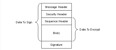
Figure 12 – MessageChunk for Authenticated Encryption Algorithms
Every MessageChunk has a Message header with the fields defined in Table 56.
Table 56 – OPC UA Secure Conversation Message Header
|
Name |
Data Type |
Description |
|
MessageType |
Byte [3] |
A three byte ASCII code that identifies the Message type. The following values are defined at this time: MSG A Message secured with the keys associated with a channel. OPN OpenSecureChannel Message. CLO CloseSecureChannel Message. |
|
IsFinal |
Byte |
A one byte ASCII code that indicates whether the MessageChunk is the final chunk in a Message. The following values are defined at this time: C An intermediate chunk. F The final chunk. A The final chunk (used when an error occurred and the Message is aborted). This field is only meaningful for MessageType of ‘MSG’ This field is always ‘F’ for other MessageTypes. |
|
MessageSize |
UInt32 |
The length of the MessageChunk, in bytes. The length starts from the beginning of the MessageType field. |
|
SecureChannelId |
UInt32 |
A unique identifier for the SecureChannel assigned by the Server. If a Server receives a SecureChannelId which it does not recognize it shall return an appropriate transport layer error. When a Server starts the first SecureChannelId used should be a value that is likely to be unique after each restart. This ensures that a Server restart does not cause previously connected Clients to accidently ‘reuse’ SecureChannels that did not belong to them. |
The Message header is followed by a security header which specifies what cryptography operations have been applied to the Message. There are two versions of the security header which depend on the type of security applied to the Message. The security header used for asymmetric algorithms is defined in Table 57. Asymmetric algorithms are used to secure the OpenSecureChannel Messages. PKCS #1 defines a set of asymmetric algorithms that may be used by UASC implementations. The AsymmetricKeyWrapAlgorithm element of the SecurityPolicy structure defined in Table 48 is not used by UASC implementations.
Table 57 – Asymmetric algorithm Security header
|
Name |
Data Type |
Description |
|
SecurityPolicyUriLength |
Int32 |
The length of the SecurityPolicyUri in bytes. This value shall not exceed 255 bytes. If a URI is not specified this value may be 0 or -1. Other negative values are invalid. |
|
SecurityPolicyUri |
Byte [] |
The URI of the Security Policy used to secure the Message. This field is encoded as a UTF-8 string without a null terminator. |
|
SenderCertificateLength |
Int32 |
The length of the SenderCertificate in bytes. This value shall not exceed MaxSenderCertificateSize bytes. If a certificate is not specified this value may be 0 or -1. Other negative values are invalid. |
|
SenderCertificate |
Byte [] |
The X.509 v3 Certificate assigned to the sending application Instance. This is a DER encoded blob. The structure of an X.509 v3 Certificate is defined in X.509 v3. The DER format for a Certificate is defined in X690 This indicates what Private Key was used to sign the MessageChunk. The Stack shall close the channel and report an error to the application if the SenderCertificate is too large for the buffer size supported by the transport layer. This field shall be null if the Message is not signed. If the Certificate is signed by a CA, the DER encoded CA Certificate may be appended after the Certificate in the byte array. If the CA Certificate is also signed by another CA this process is repeated until the entire Certificate chain is in the buffer or if MaxSenderCertificateSize limit is reached (the process stops after the last whole Certificate that can be added without exceeding the MaxSenderCertificateSize limit). Receivers can extract the Certificates from the byte array by using the Certificate size contained in DER header (see X.509 v3). Receivers that do not handle Certificate chains shall ignore the extra bytes. |
|
ReceiverCertificateThumbprintLength |
Int32 |
The length of the ReceiverCertificateThumbprint in bytes. When using RSA Public Keys: If encrypted, the value of this field is 20 bytes. If not encrypted the value may be 0 or -1. When using ECC Public Keys: The value of this field is 20 bytes. Other negative values are invalid. |
|
ReceiverCertificateThumbprint |
Byte [] |
The thumbprint of the X.509 v3 Certificate assigned to the receiving application Instance. The thumbprint is the CertificateDigest of the DER encoded form of the Certificate. When using RSA Public Keys it indicates which Public Key was used to encrypt the MessageChunk. When using ECC Public Keys it indicates the intended recipient of the MessageChunk. |
The receiver shall close the communication channel if any of the fields in the security header have invalid lengths.
The SenderCertificate, including any chains, shall be small enough to fit into a single MessageChunk and leave room for at least one byte of body information. The maximum size for the SenderCertificate can be calculated with this formula:
MaxSenderCertificateSize =
MessageChunkSize –
12 - // Header size
4 - // SecurityPolicyUriLength
SecurityPolicyUri - // UTF-8 encoded string
4 - // SenderCertificateLength
4 - // ReceiverCertificateThumbprintLength
20 - // ReceiverCertificateThumbprint
8 - // SequenceHeader size
1 - // Minimum body size
1 - // PaddingSize if present
Padding - // Padding if present
ExtraPadding - // ExtraPadding if present
AsymmetricSignatureSize // If present
The MessageChunkSize depends on the transport protocol but shall be at least 8192 bytes. The AsymmetricSignatureSize depends on the number of bits in the public key for the SenderCertificate. The Int32FieldLength is the length of an encoded Int32 value and it is always 4 bytes.
The security header used for symmetric algorithms defined in Table 58. Symmetric algorithms are used to secure all Messages other than the OpenSecureChannel Messages. FIPS 197 define symmetric encryption algorithms that UASC implementations may use. FIPS 180- and HMAC define some symmetric signature algorithms.
Table 58 – Symmetric algorithm Security header
|
Name |
Data Type |
Description |
|
TokenId |
UInt32 |
A unique identifier for the SecureChannel SecurityToken used to secure the Message. This identifier is returned by the Server in an OpenSecureChannel response Message. If a Server receives a TokenId which it does not recognize it shall return an appropriate transport layer error. |
The security header is always followed by the sequence header which is defined in Table 59. The sequence header ensures that the first encrypted block of every Message sent over a channel will start with different data.
Table 59 – Sequence header
|
Name |
Data Type |
Description |
|
SequenceNumber |
UInt32 |
A monotonically increasing sequence number assigned by the sender to each MessageChunk sent over the SecureChannel. |
|
UInt32 |
An identifier assigned by the Client to OPC UA request Message. All MessageChunks for the request and the associated response use the same identifier. |
A SequenceNumber may not be reused for any TokenId. The SecurityToken lifetime shall be short enough to ensure that this never happens; however, if it does the receiver shall treat it as a transport error and force a reconnect. The SequenceNumber does not reset when a new TokenId is issued and it shall be incremented by exactly one for each MessageChunk sent.
SecurityPolicies with LegacySequenceNumbers set to TRUE, the SequenceNumber shall monotonically increase for all Messages and shall not wrap around until it is greater than 4,294,966,271 (UInt32.MaxValue – 1024). The first number after the wrap around shall be less than 1024.
SecurityPolicies with LegacySequenceNumbers set to FALSE, the SequenceNumber shall start at 0 and monotonically increase for all Messages and shall not wrap around until it is equal to 4294967295 (UInt32.MaxValue). The first number after the wrap around shall be 0.
Some applications will find it takes time to validate the OpenSecureChannel Requests and Responses used to renew a TokenId. In these situations, the receiver may assume the SequenceNumber is correct which allows it to process subsequent messages secured with the existing TokenId before the OpenSecureChannel Message is validated. When processing of the OpenSecureChannel Message completes, the receiver checks the SequenceNumber and closes the SecureChannel if it is incorrect.
The sequence header is followed by the Message body which is encoded with the OPC UA Binary encoding as described in 1.1.18. The body may be split across multiple MessageChunks.
Each MessageChunk when using SecurityPolicies with an Unauthenticated Encryption algorithms have a footer with the fields defined in Table 60.
Table 60 – Message Footer for Unauthenticated Encryption Algorithms
|
Name |
Data Type |
Description |
|
PaddingSize |
Byte |
The number of padding bytes (not including the byte for the PaddingSize). |
|
Padding |
OctetString |
Padding added to the end of the Message to ensure length of the data to encrypt is an integer multiple of the encryption block size. The value of each byte of the padding is equal to PaddingSize. |
|
ExtraPaddingSize |
Byte |
The most significant byte of a two-byte integer used to specify the padding size when the key used to encrypt the message chunk is larger than 2048 bits. This field is omitted if the key length is less than or equal to 2048 bits. |
|
Signature |
OctetString |
The signature for the MessageChunk. The signature includes the headers, all Message data, the PaddingSize and the Padding. The signature is encoded as sequence of Bytes with a length specified by the SecurityPolicy. |
The formula to calculate the amount of padding depends on the amount of data that needs to be sent (called BytesToWrite). The sender shall first calculate the maximum amount of space available in the MessageChunk (called MaxBodySize) using the following formula:
MaxBodySize =
PlainTextBlockSize * Floor ((MessageChunkSize
– MessageHeaderSize
- SecurityHeaderSize
– SignatureSize - 1)/CipherTextBlockSize) – SequenceHeaderSize;
The MessageHeaderSize is 12 bytes and the SecurityHeader size depends on whether symmetric or asymmetric cryptography is used. The SequenceHeaderSize is always 8 bytes.
During encryption a block with a size equal to PlainTextBlockSize is processed to produce a block with size equal to CipherTextBlockSize. These values depend on the encryption algorithm and may be the same.
The OPC UA Message can fit into a single chunk if BytesToWrite is less than or equal to the MaxBodySize. In this case the PaddingSize is calculated with this formula:
PaddingSize = PlainTextBlockSize –
((BytesToWrite + SignatureSize + 1) % PlainTextBlockSize);
If the BytesToWrite is greater than MaxBodySize the sender shall write MaxBodySize bytes with a PaddingSize of 0. The remaining BytesToWrite – MaxBodySize bytes shall be sent in subsequent MessageChunks.
The PaddingSize and Padding fields are not present if the MessageChunk is not encrypted.
The Signature field is not present if the MessageChunk is not signed.
Each MessageChunk when using SecurityPolicies with an Authenticated Encryption algorithms have a footer with the fields defined in Table 61.
Table 61 – Message Footer for Authenticated Encryption Algorithms
|
Name |
Data Type |
Description |
|
Signature |
OctetString |
The signature for the MessageChunk. The signature includes the headers and all Message data. The signature is encoded as sequence of Bytes with a length specified by the SecurityPolicy. |
MessageChunks are sent as they are encoded. MessageChunks belonging to the same Message shall be sent sequentially. If an error occurs creating a MessageChunk then the sender shall send a final MessageChunk to the receiver that tells the receiver that an error occurred and that it should discard the previous chunks. The sender indicates that the MessageChunk contains an error by setting the IsFinal flag to ‘A’ (for Abort). Table 62 specifies the contents of the Message abort MessageChunk.
Table 62 – OPC UA Secure Conversation Message abort body
|
Name |
Data Type |
Description |
|
Error |
UInt32 |
The numeric code for the error. Possible values are listed in Table 77. |
|
Reason |
String |
A more verbose description of the error. This string shall not be more than 4096 bytes. A Client shall ignore strings that are longer than this. Any security related information shall not be returned. This includes any indication of the reason that caused Bad_SecurityChecksFailed to be returned. |
The receiver shall check the security on the abort MessageChunk before processing it. If everything is ok, then the receiver shall ignore the Message but shall not close the SecureChannel. The Client shall report the error back to the application as StatusCode for the request. If the Client is the sender, then it shall report the error without waiting for a response from the Server.
Most Messages require a SecureChannel to be established. A Client does this by sending an OpenSecureChannel request to the Server. The Server shall validate the Message and the ClientCertificate and return an OpenSecureChannel response. Some of the parameters defined for the OpenSecureChannel service are specified in the security header (see 0.1.42) instead of the body of the Message. Table 63 lists the parameters that appear in the body of the Message.
Note that OPC 10000-4 is an abstract specification which defines interfaces that can work with any protocol. This document provides a concrete implementation for specific protocols. This document is the normative reference for all protocols and takes precedence if there are differences with OPC 10000-4.
Table 63 – OPC UA Secure Conversation OpenSecureChannel Service
|
Name |
Data Type |
|
Request |
|
|
RequestHeader |
RequestHeader |
|
ClientProtocolVersion |
UInt32 |
|
RequestType |
SecurityTokenRequestType |
|
SecurityMode |
MessageSecurityMode |
|
ClientNonce |
ByteString |
|
RequestedLifetime |
UInt32 |
|
|
|
|
Response |
|
|
ResponseHeader |
ResponseHeader |
|
ServerProtocolVersion |
UInt32 |
|
SecurityToken |
ChannelSecurityToken |
|
SecureChannelId |
UInt32 |
|
TokenId |
UInt32 |
|
CreatedAt |
UtcTime |
|
RevisedLifetime |
UInt32 |
|
ServerNonce |
ByteString |
The ClientProtocolVersion and ServerProtocolVersion parameters are not defined in OPC 10000-4 and are added to the Message to allow backward compatibility if OPC UA-SecureConversation needs to be updated in the future.
If OPC UA-SecureConversation is used with the OPC UA-TCP protocol (see 7.1) then the ClientProtocolVersion specified in the OpenSecureChannel Request shall be the same as the ProtocolVersion specified in the Hello Message. In addition, the ServerProtocolVersion specified in the OpenSecureChannel Response shall be the same as the ProtocolVersion specified in the Acknowledge Message. The receiver shall close the channel and report a Bad_ProtocolVersionUnsupported error if there is a mismatch.
The Server shall return an error response as described in OPC 10000-4 if there are any errors with the parameters specified by the Client.
The Server shall accept requests secured with the old SecurityToken until that SecurityToken expires or until it receives a Message from the Client secured with the new SecurityToken. The Server shall reject renew requests if the SenderCertificate is not the same as the one used to create the SecureChannel or if there is a problem decrypting or verifying the signature.
The datatype of the RevisedLifetime is a UInt32 value representing the number of milliseconds instead of the Double (Duration) defined in OPC 10000-4. This optimization is possible because sub-millisecond timeouts are not supported.
The OpenSecureChannel Messages are signed and encrypted if the SecurityMode is not None (even if the SecurityMode is Sign).
The Nonces shall be cryptographic random numbers with a length specified by the SecureChannelNonceLength of the SecurityPolicy.
See OPC 10000-2 for more information on the requirements for random number generators. The OpenSecureChannel Messages are not signed or encrypted if the SecurityMode is None. The Nonces are ignored and should be set to null. The SecureChannelId and the TokenId are still assigned but no security is applied to Messages exchanged via the channel. The SecurityToken shall still be renewed before the RevisedLifetime expires. Receivers shall still ignore invalid or expired TokenIds.
The AuthenticationToken in the RequestHeader shall be set to null.
If an error occurs after the Server has verified Message security it shall return a ServiceFault instead of a OpenSecureChannel response. The ServiceFault Message is described in OPC 10000-4.
If the SecurityMode is not None then the Server shall verify that a SenderCertificate and a ReceiverCertificateThumbprint were specified in the SecurityHeader.
Once the SecureChannel is established the Messages are signed and encrypted with keys derived from the Nonces exchanged in the OpenSecureChannel call. These keys are derived by passing the Nonces to a pseudo-random function (PRF) which produces a sequence of bytes from a set of inputs. A pseudo-random function is represented by the following function declaration:
Byte[] PRF(
Byte[] secret,
Byte[] seed,
Int32 length,
Int32 offset)
Where length is the number of bytes to return and offset is a number of bytes from the beginning of the sequence.
The lengths of the keys that need to be generated depend on the SecurityPolicy used for the channel. The following information is specified by the SecurityPolicy:
a) SigningKeyLength (from the DerivedSignatureKeyLength);
b) EncryptingKeyLength (implied by the SymmetricEncryptionAlgorithm);
c) InitializationVectorLength (from by the InitializationVectorLength).
The pseudo random function requires a secret and a seed. These values are derived from the Nonces exchanged in the OpenSecureChannel request and response. Table 64 specifies how to derive the secrets and seeds when using RSA based SecurityPolicies.
Table 64 – PRF inputs for RSA based SecurityPolicies
|
Name |
Derivation |
|
ClientSecret |
The value of the ClientNonce provided in the OpenSecureChannel request. |
|
ClientSeed |
The value of the ClientNonce provided in the OpenSecureChannel request. |
|
ServerSecret |
The value of the ServerNonce provided in the OpenSecureChannel response. |
|
ServerSeed |
The value of the ServerNonce provided in the OpenSecureChannel response. |
The parameters passed to the pseudo random function are specified in Table 65.
Table 65 – Cryptography key generation parameters
|
Key |
Secret |
Seed |
Length |
Offset |
|
ClientSigningKey |
ServerSecret |
ClientSeed |
SigningKeyLength |
0 |
|
ClientEncryptingKey |
ServerSecret |
ClientSeed |
EncryptingKeyLength |
SigningKeyLength |
|
ClientInitializationVector |
ServerSecret |
ClientSeed |
InitializationVectorLength |
SigningKeyLength+EncryptingKeyLength |
|
ServerSigningKey |
ClientSecret |
ServerSeed |
SigningKeyLength |
0 |
|
ServerEncryptingKey |
ClientSecret |
ServerSeed |
EncryptingKeyLength |
SigningKeyLength |
|
ServerInitializationVector |
ClientSecret |
ServerSeed |
InitializationVectorLength |
SigningKeyLength+EncryptingKeyLength |
The Client keys are used to secure Messages sent by the Client. The Server keys are used to secure Messages sent by the Server.
The TLS specification defines a pseudo random function called P_HASH which is used for this purpose. The function is iterated until it produces enough data for all of the required keys. The Offset in Table 65 references to the offset from the start of the generated data.
The P_ hash algorithm is defined as follows:
P_HASH(secret, seed) = HMAC_HASH(secret, A(1) + seed) +
HMAC_HASH(secret, A(2) + seed) +
HMAC_HASH(secret, A(3) + seed) + ...
Where A(n) is defined as:
A(0) = seed
A(n) = HMAC_HASH(secret, A(n-1))
+ indicates that the results are appended to previous results.
Where ‘HASH’ is a hash function such as SHA256. The hash function to use depends on the SecurityPolicyUri.
The contents of the MessageChunk shall not be interpreted until the Message is decrypted and the signature and sequence number verified.
If an error occurs during Message verification the receiver shall close the communication channel. If the receiver is the Server, it shall also send a transport error Message before closing the channel. Once the channel is closed the Client shall attempt to re-open the channel and request a new SecurityToken by sending an OpenSecureChannel request. The mechanism for sending transport errors to the Client depends on the communication channel.
The receiver shall first check the SecureChannelId. This value may be 0 if the Message is an OpenSecureChannel request. For other Messages, it shall report a Bad_SecureChannelUnknown error if the SecureChannelId is not recognized. If the Message is an OpenSecureChannel request and the SecureChannelId is not 0 then the SenderCertificate shall be the same as the SenderCertificate used to create the channel.
If the Message is secured with asymmetric algorithms, then the receiver shall verify that it supports the requested SecurityPolicy. If the Message is the response sent to the Client, then the SecurityPolicy shall be the same as the one specified in the request. In the Server, the SecurityPolicy shall be the same as the one used to originally create the SecureChannel.
The receiver shall verify the ReceiverCertificateThumbprint and report a Bad_CertificateInvalid error if it does not recognize it.
The receiver shall check that the Certificate is trusted first and return Bad_SecurityChecksFailed on error. The receiver shall then verify the SenderCertificate using the rules defined in OPC 10000-4. The receiver shall report the appropriate error if Certificate validation fails.
If the Message is secured with symmetric algorithms, then a Bad_SecureChannel TokenUnknown error shall be reported if the TokenId refers to a SecurityToken that has expired or is not recognized.
If decryption or signature validation fails, then a Bad_SecurityChecksFailed error is reported. If an implementation allows multiple SecurityModes to be used the receiver shall also verify that the Message was secured properly as required by the SecurityMode specified in the OpenSecureChannel request.
After the security validation is complete the receiver shall verify the RequestId and the SequenceNumber. If these checks fail a Bad_SecurityChecksFailed error is reported. The RequestId only needs to be verified by the Client since only the Client knows if it is valid or not. If the SequenceNumber is not valid, the receiver shall log a Bad_SequenceNumberInvalid error.
At this point the SecureChannel knows it is dealing with an authenticated Message that was not tampered with or resent. This means the SecureChannel can return secured error responses if any further problems are encountered.
Stacks that implement UASC shall have a mechanism to log errors when invalid Messages are discarded. This mechanism is intended for developers, systems integrators and administrators to debug network system configuration issues and to detect attacks on the network.
The OPC UA Secure Conversation (UASC) mechanism described 6.7 is designed for use with asymmetric cryptography algorithms, such as RSA, that allow Public Keys to be used for encryption and for digital signatures. ECC is an asymmetric cryptography algorithm that only supports digital signatures. To accommodate algorithms like ECC, the UASC handshake needs to be modified to allow negotiation of inputs used for key derivation in 1.1.45 without making the keys available to eavesdroppers. This negotiation uses a Diffie Hellman algorithm defined in RFC 8422 and is shown in Figure 13.
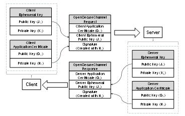
Figure 13 – ECC Key Negotiation
ApplicationInstance Certificates for ECC have a public-private key pair that are used to create and verify a digital signature. To negotiate the keys needed for the SecureChannel the Client generates a new key pair (JC, KC) and passes the Public Key (JC) in the request. After verifying the signature on the request, the Server generates a new key pair (JS, KS) and returns the Public Key (JS) in the response. The new key pairs are used each time a SecureChannel is negotiated and they are called EphemeralKeys.
ECC public-private key pairs are always based on a specific elliptic curve function which is used for the ECC calculations. Many curves exist, however, ECC cryptography libraries support a finite set of “named curves” to allow for better interoperability. Each OPC UA SecurityPolicy defined in OPC 10000-7 specifies exactly one named curve which is used for the EphemeralKeys.
Each ECC ApplicationInstance Certificate is also based on a named curve. Each SecurityPolicy specifies a list of named curves which are permitted for use in the ApplicationInstance Certificate. This list always includes the named curved used for the EphemeralKey, however, it may allow other named curves. OPC UA applications that support ECC SecurityPolicies will need to support multiple ApplicationInstance Certificates.
ECC Public Keys and digital signatures are the output of an ECC operation. The encoding of these outputs depends on the ECC curve and are described by the SecurityPolicy in OPC 10000-7.
Clause 6.7.4 specifies the contents of the OpenSecureChannel request and response messages. When using an ECC SecurityPolicy the ClientNonce is the Public Key for the Client’s EphemeralKey encoded using the Public Key encoding for the curve. Similarly, the ServerNonce is the Public Key for the Server’s EphemeralKey.
The encoding of the EphemeralKeys depends on the ECC curve used. For NIST and Brainpool curves the EphemeralKey is the x and y coordinate encoded as zero padded big-endian OctetString. For Edwards curves the EphemeralKey format is defined by RFC 7748.
The EphemeralKeys are used to calculate a shared secret by using the Private Key of an EphemeralKey and the Public Key of the peer’s EphemeralKey. The exact algorithm to calculate the shared secret depends on the ECC curve and is defined by the SecurityPolicy. This shared secret is then used to derive key data using the following algorithm from RFC 5869. Note that the algorithm is repeated here for clarity, however, the RFC is the normative source.
Step 1: Calculate Salts
ServerSalt = L | UTF8(opcua-server) | ServerNonce | ClientNonce ClientSalt = L | UTF8(opcua-client) | ClientNonce | ServerNonce
Where
· L is the length of derived key material needed encoded as a 16-bit little endian integer;
· UTF8(label) is the UTF8 encoding of the string literal ‘label’;
· ServerNonce is the Server EphemeralKey from the OpenSecureChannel response;
· ClientNonce is the Client EphemeralKey from the OpenSecureChannel request;
· | concatenates sequences of bytes;
· Salt is a sequence of bytes.
Step 2: Extract
PRK = HMAC-Hash(Salt, IKM)
Where
· HMAC uses a Hash function specified by the KeyDerivationAlgorithm;
· IKM is the x-coordinate of the shared secret;
· Salt is calculated in Step 1;
· PRK is a pseudorandom output with length equal to the Hash size.
The encoding of the x-coordinate depends on the ECC curve used. For NIST and Brainpool curves the x-coordinate is encoded as a zero padded big-endian OctetString. For Edwards curves the coordinate format is defined by RFC 7748.
Step 3: Expand
N = ceil(L/HashLen)T = T(1) | T(2) | T(3) | ... | T(N)
OKM = first L octets of T where: T(0) = empty string (zero length)T(1) = HMAC-Hash(PRK, T(0) | Info | 0x01)
T(2) = HMAC-Hash(PRK, T(1) | Info | 0x02) T(3) = HMAC-Hash(PRK, T(2) | Info | 0x03) ...
Where
· HMAC uses a Hash function specified by the KeyDerivationAlgorithm;
· PRK is the output from Step 1;
· Info is a sequence of bytes;
· L is the length of keying material needed;
· 0x01 is the number 1 encoded as a byte.
· OKM is the output with length equal to L bytes.
The client keys are extracted from the keying material created with IKM=shared secret, Salt=ClientSalt and Info=ClientSalt as shown in Table 66.
Table 66 – Deriving Client Keys from Keying Material
|
Name |
Offset |
Length |
|
ClientSigningKey |
0 |
DerivedSignatureKeyLength |
|
ClientEncryptingKey |
DerivedSignatureKeyLength |
EncryptionKeyLength |
|
ClientInitializationVector |
DerivedSignatureKeyLength + EncryptionKeyLength |
InitializationVectorLength |
The server keys are extracted from the keying material created with IKM=shared secret, Salt= ServerSalt and Info=ServerSalt as shown in Table 67.
Table 67 – Deriving Server Keys from Keying Material
|
Name |
Offset |
Length |
|
ServerSigningKey |
0 |
DerivedSignatureKeyLength |
|
ServerEncryptingKey |
DerivedSignatureKeyLength |
EncryptionKeyLength |
|
ServerInitializationVector |
DerivedSignatureKeyLength + EncryptionKeyLength |
InitializationVectorLength |
The SymmetricEncryptionAlgorithm for the SecurityPolicy sets the EncryptionKeyLength and EncryptionBlockSize.
When using AuthenticatedEncryption, the SigningKey, EncryptingKey and InitializationVector are always calculated, however, only the EncryptingKey and InitializationVector are used. The only difference between Sign and SignAndEncrypt is the length of encrypted data which is zero when Sign is used. The process of signing and encrypting data with AuthenticatedEncryption is illustrated in Figure 14.
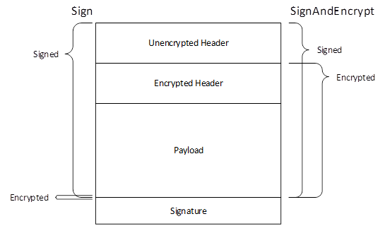
Figure 14 – Signing and Encryption with Authenticated Encryption
When using UnauthenticatedEncryption with Sign only the SigningKey needs to be computed, however, the length of the derived key material used to calculate the Salt shall be the same as the length of the derived key material used with SignAndEncrypt. The encryption algorithm is not used and the padding is zero length when using Sign mode. The process of signing and encrypting data with UnauthenticatedEncryption is illustrated in Figure 15.
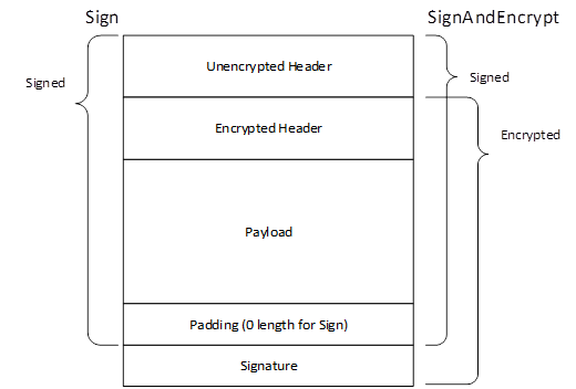
Figure 15 – Signing and Encryption with Unauthenticated Encryption
In addition, a unique InitializationVector is needed for each Message. This value constructed from the ClientInitializationVector or ServerInitializationVector where the first 8 bytes are XORed with the values in Table 68 encoded as described in 5.2.1.2.
Table 68 – Creating a Mask for the Initialization Vector
|
Name |
Bytes |
Length |
|
TokenId |
4 |
The TokenId specified in the SecurityHeader of MessageChunk being processed. It is encoded as a UInt32 as described in 5.2.2.2. |
|
LastSequenceNumber |
4 |
The SequenceNumber specified in the SequenceHeader of last MessageChunk sent in the same direction on the SecureChannel. The value is 0 to indicate there is no LastSequenceNumber for the first MessageChunk which is always the OpenSecureChannel Message. It is encoded as a UInt32 as described in 5.2.2.2. |
The ClientInitializationVector is used when the Client encrypts the MessageChunk and the ServerInitializationVector is used when the Server encrypts the MessageChunk.
The LastSequenceNumber is the SequenceNumber from the previously sent Message which normally requires the previous Message to be decrypted. If the receiver processes incoming Messages in parallel it can calculate the expected SequenceNumber based on the order in which the encrypted Messages are received.
Once the keys are derived ECC SecureChannels behave the same as RSA SecureChannels.
ActivateSession allows a Client to provide an encrypted UserIdentityToken using a SecurityPolicy specified by a UserTokenPolicy supported by the current Endpoint. With ECC, encryption requires that the Client and Server exchange EphemeralKeys and there is no mechanism in the current CreateSession/ActivateSession handshake to do this. For that reason, EphemeralKeys are returned in the AdditionalHeader field of the ResponseHeader of the CreateSession and ActivateSession responses. An overview of the handshake is shown in Figure 16.
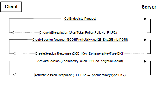
Figure 16 – ECC CreateSession/ActivateSession Handshake
The UserTokenPolicies are returned in the GetEndpoints response. A UserTokenPolicy may specify a SecurityPolicyUri that is different than the SecureChannel, however, all UserTokenPolicies in an EndpointDescription shall specify a SecurityPolicyUri that is valid for all Certificates that are valid for SecurityPolicyUri specified in the EndpointDescription. For example, an EndpointDescription providing an ECC SecurityPolicyUri shall not specify RSA SecurityPolicyUris in the UserTokenPolicies.
When a Client calls CreateSession via a SecureChannel based on an ECC SecurityPolicy the Client specifies the SecurityPolicyUri it plans to use for the UserIdentityToken in the RequestHeader. Server returns an EphemeralKey in the ResponseHeader that can be used for the SecurityPolicyUri specified by the Client. If the SecurityPolicyUri is not valid the Server returns a StatusCode in the ResponseHeader instead of an EphemeralKey.
When the Client calls ActivateSession it creates an EccEncryptedSecret (see OPC 10000-4) using the EphemeralKey provided in CreateSession response. The Server always returns a new EphemeralKey in the ResponseHeader which the Client saves for when it calls ActivateSession again. The SecurityPolicyUri passed in CreateSession is used to determine what type of EphemeralKey to return.
The EphemeralKeys may be used for exactly one key negotiation. After that they are discarded. Each time ActivateSession is called the UserIdentityToken is encrypted using the last EphemeralKey returned by the Server. The EphemeralKey is changed even if the Client did not provide an encrypted UserIdentityToken.
If the Client does not provide SecurityPolicyUri in the call to CreateSession it will not be able to use any UserIdentityTokens that require encryption with ECC SecurityProfiles.
OPC 10000-4 defines AdditionalParametersType which is a list of name-value pairs. An instance of this type is passed in the AdditionalHeader field. Instances of the EphemeralKeyType defined in OPC 10000-4 are passed as values in the name-value pair list in the response messages. The names used for the parameters defined for the CreateSession/ActivateSession exchange are defined in Table 69.
Table 69 – Additional Header Key Names
|
Name |
DataType |
Description |
|
ECDHPolicyUri |
String |
Specifies the SecurityPolicyUri used for the EphemeralKeys. |
|
ECDHKey |
EphemeralKeyType |
Specifies an EphemeralKey. If the EphemeralKey could not be created a StatusCode indicating the reason for the error is used instead of an instance of EphemeralKeyType. |
OPC 10000-4 defines the layout of EccEncryptedSecret structure which is used to protect secrets with ECC SecurityPolicies. Applying security with ECC requires two EphemeralKeys generated by the sender and the receiver which are used create the symmetric keys need for encryption.
6.7.2 defines a mechanism to allows the sender to acquire the receiver EphemeralKey when using a Session. Using the EccEncryptedSecret in other contexts requires a different mechanism.
Once the sender has the receiver EphemeralKey, it creates its own EphemeralKey. The ECC curve and key length for the EphemeralKeys are specified by the SecurityPolicyUri.
The encryption uses the symmetric encryption algorithm specified by the SecurityPolicyUri. The encrypting key and initialization vector are generated by using the EphemeralKeys to create the shared secret and then derive keys using the algorithm defined in 6.7.2. Step 1 is slightly different and defined as follows:
Step 1: Calculate Salt
SecretSalt = L | UTF8(opcua-secret) | SenderPublicKey | ReceiverPublicKey
Where:
· L is the length of derived key material needed encoded as a 16-bit little endian integer;
· UTF8(opcua-secret) is the UTF8 encoding of the string literal ‘opcua-secret’;
· SenderPublicKey and ReceiverPublicKey are from the PolicyHeader;
· | concatenates sequences of bytes;
Salt is a sequence of bytes.
The encryption keys are extracted from the keying material created with IKM=shared secret, Salt=SecretSalt and Info=SecretSalt as shown in Table 70.
Table 70 – Deriving Keys from Keying Material
|
Name |
Offset |
Length |
|
EncryptingKey |
0 |
EncryptionKeyLength |
|
InitializationVector |
EncryptionKeyLength |
InitializationVectorLength |
The EncryptionKeyLength and EncryptionBlockSize are specified by the Symmetric Encryption Algorithm for the SecurityPolicy. The Signature is created with the SigningCertificate and is calculated after encryption. Receivers shall validate the SigningCertificate and signature before decrypting the Secret.
OPC UA Connection Protocol (UACP) is an abstract protocol that establishes a full duplex channel between a Client and Server. Concrete implementations of the UACP can be built with any middleware that supports full-duplex exchange of messages including TCP/IP and WebSockets. The term “TransportConnection” describes the specific connection used to exchange messages. For example, a socket is the TransportConnection for TCP/IP. TransportConnections allow responses to be returned in any order. If the TransportConnection breaks the SecureChannel is interrupted and a new SecureChannel needs to be created.
The OPC UA Connection Protocol is designed to work with the SecureChannel implemented by a layer higher in the stack. For this reason, the OPC UA Connection Protocol defines its interactions with the SecureChannel in addition to the wire protocol.
Figure 17 illustrates the structure of a Message placed on the wire. This also illustrates how the Message elements defined by the OPC UA Binary Encoding mapping (see 5.2) and the OPC UA Secure Conversation mapping (see 6.7) relate to the OPC UA Connection Protocol Messages.
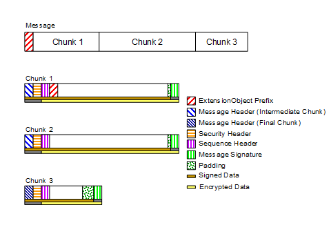
Figure 17 – OPC UA Connection Protocol Message structure
Every OPC UA Connection Protocol Message has a header with the fields defined in Table 71.
Table 71 – OPC UA Connection Protocol Message header
|
Name |
Type |
Description |
|
MessageType |
Byte [3] |
A three byte ASCII code that identifies the Message type. The following values are defined at this time: HEL a Hello Message. ACK an Acknowledge Message. ERR an Error Message. RHE a ReverseHello Message. The SecureChannel layer defines additional values which the OPC UA Connection Protocol layer shall accept. |
|
Reserved |
Byte [1] |
Ignored. shall be set to the ASCII codes for ‘F’ if the MessageType is one of the values supported by the OPC UA Connection Protocol. |
|
MessageSize |
UInt32 |
The length of the Message, in bytes. This value includes the 8 bytes for the Message header. |
The layout of the OPC UA Connection Protocol Message header is intentionally identical to the first 8 bytes of the OPC UA Secure Conversation Message header defined in Table 56. This allows the OPC UA Connection Protocol layer to extract the SecureChannel Messages from the incoming stream even if it does not understand their contents.
The OPC UA Connection Protocol layer shall verify the MessageType and make sure the MessageSize is less than the negotiated ReceiveBufferSize before passing any Message onto the SecureChannel layer.
The Hello Message has the additional fields shown in Table 72.
Table 72 – OPC UA Connection Protocol Hello Message
|
Name |
Data Type |
Description |
|
ProtocolVersion |
UInt32 |
The version of the UACP protocol requested by the Client. If Server does not support the requested version or any lower version it rejects the Client by returning Bad_ProtocolVersionUnsupported. If the Server supports the requested version or a lower version it shall return the version it will use in the Acknowledge Message. The ProtocolVersion for this version of the standard is 0. |
|
ReceiveBufferSize |
UInt32 |
The largest MessageChunk that the sender can receive. Shall be at least 1024 bytes if the sender intends to use an ECC SecurityPolicy. Shall be at least 8192 bytes otherwise. |
|
SendBufferSize |
UInt32 |
The largest MessageChunk that the sender will send. Shall be at least 1024 bytes if the sender intends to use an ECC SecurityPolicy. Shall be at least 8192 bytes otherwise. |
|
MaxMessageSize |
UInt32 |
The maximum size for any response Message. If MessageChunks have not been sent, the Server shall return an Error Message with a Bad_ResponseTooLarge error if a response Message exceeds this value. If MessageChunks have already been sent the Server shall abort the Message as described in 1.1.43. The Message size is calculated using the unencrypted Message body. A value of zero indicates that the Client has no limit. |
|
MaxChunkCount |
UInt32 |
The maximum number of chunks in any response Message. The Server shall abort the Message with a Bad_ResponseTooLarge Error Message if a response Message exceeds this value. The mechanism for aborting Messages is described fully in 1.1.43. A value of zero indicates that the Client has no limit. |
|
EndpointUrl |
String |
The URL of the Endpoint which the Client wished to connect to. The encoded value shall be less than 4096 bytes. Servers shall return a Bad_TcpEndpointUrlInvalid Error Message and close the connection if the length exceeds 4096 or if it does not recognize the resource identified by the URL. |
The EndpointUrl parameter is used to allow multiple Servers to share the same endpoint on a machine. The process listening (also known as the proxy) on the endpoint would connect to the Server identified by the EndpointUrl and would forward all Messages to the Server via this socket. If one socket closes, then the proxy shall close the other socket.
If the Server does not have sufficient resources to allow the establishment of a new SecureChannel it shall immediately return a Bad_TcpNotEnoughResources Error Message and gracefully close the socket. Client should not overload Servers that return this error by immediately trying to create a new SecureChannel.
The Acknowledge Message has the additional fields shown in Table 73.
Table 73 – OPC UA Connection Protocol Acknowledge Message
|
Name |
Type |
Description |
|
ProtocolVersion |
UInt32 |
A protocol version supported by the Server that is less than or equal to the protocol version requested in the Hello Message. If the Client accepts the protocol version it shall ensure that it sends Messages that conform to this version. The ProtocolVersion for this version of the standard is 0. |
|
ReceiveBufferSize |
UInt32 |
The largest MessageChunk that the sender can receive. This value shall not be larger than the SendBufferSize requested in the Hello Message. Shall be at least 8192 bytes if the SendBufferSize requested in the Hello Message is >= 8192 bytes. Shall be at least 1024 bytes otherwise. |
|
SendBufferSize |
UInt32 |
The largest MessageChunk that the sender will send. This value shall not be larger than the ReceiveBufferSize requested in the Hello Message. Shall be at least 8192 bytes if the ReceiveBufferSize requested in the Hello Message is >= 8192 bytes. Shall be at least 1024 bytes otherwise. |
|
MaxMessageSize |
UInt32 |
The maximum size for any request Message. If a request Message exceeds this value the Client shall report a Bad_ Bad_RequestTooLarge error to the application. If MessageChunks have already been sent the Client shall also abort the Message as described in 1.1.43. The Message size is calculated using the unencrypted Message body. A value of zero indicates that the Server has no limit. |
|
MaxChunkCount |
UInt32 |
The maximum number of chunks in any request Message. The Client shall abort the Message with a Bad_RequestTooLarge StatusCode if a request Message exceeds this value. The mechanism for aborting Messages is described fully in 1.1.43. A value of zero indicates that the Server has no limit. |
The Error Message has the additional fields shown in Table 74.
Table 74 – OPC UA Connection Protocol Error Message
|
Name |
Type |
Description |
|
Error |
UInt32 |
The numeric code for the error. Possible values are listed in Table 77. |
|
Reason |
String |
A more verbose description of the error. This string shall not be more than 4096 bytes. A Client shall ignore strings that are longer than this. |
The socket is always closed gracefully by the Client after it receives an Error Message.
The ReverseHello Message has the additional fields shown in Table 75.
Table 75 – OPC UA Connection Protocol ReverseHello Message
|
Name |
Data Type |
Description |
|
ServerUri |
String |
The ApplicationUri of the Server which sent the Message. The encoded value shall be less than 4096 bytes. Client shall return a Bad_TcpEndpointUrlInvalid error and close the connection if the length exceeds 4096 or if it does not recognize the Server identified by the URI. |
|
EndpointUrl |
String |
The URL of the Endpoint which the Client uses when establishing the SecureChannel. This value shall be passed back to the Server in the Hello Message. The encoded value shall be less than 4096 bytes. Clients shall return a Bad_TcpEndpointUrlInvalid error and close the connection if the length exceeds 4096 or if it does not recognize the resource identified by the URL. This value is a unique identifier for the Server which the Client may use to look up configuration information. It should be one of the URLs returned by the GetEndpoints Service. |
For connection-based protocols, such as TCP, the ReverseHello Message allows Servers behind firewalls with no open ports to connect to a Client and request that the Client establish a SecureChannel using the socket created by the Server.
For message-based protocols the ReverseHello Message allows Servers to announce their presence to a Client. In this scenario, the EndpointUrl specifies the Server’s specific address and any tokens required to access it.
Connections may be initiated by the Client or by the Server when they create a TransportConnection and establish a communication with their peer. The connection is initiated by using an EndpointUrl that specifies a network address where a peer listens for new connections. The EndpointUrl specifies a network address that is accessible to the initiator. If the listener is behind a NAT firewall, the EndpointUrl specifies an address outside the firewall. If the EndpointUrl specifies a domain name then the initiator requires access to a domain name resolution service (e.g., the DNS protocol) that maps the domain name onto a usable network address. OPC 10000-7 defines Profiles for different name resolution protocols that Clients and Servers may support.
If the Client creates the TransportConnection, the first Message sent shall be a Hello which specifies the buffer sizes that the Client supports. The Server shall respond with an Acknowledge Message which completes the buffer negotiation. The negotiated buffer size shall be reported to the SecureChannel layer. The negotiated SendBufferSize specifies the size of the MessageChunks to use for Messages sent over the connection.
If the Server creates the TransportConnection the first Message shall be a ReverseHello sent to the Client. If the Client accepts the connection, it sends a Hello message back to the Server which starts the buffer negotiation described for the Client initiated connection.
The Hello/Acknowledge Messages may only be sent once. If they are received again the receiver shall report an error and close the TransportConnection. Applications accepting incoming connections shall close any TransportConnection after a period of time if it does not receive a Hello or ReverseHello Message. This period of time shall be configurable and have a default value which does not exceed two minutes.
The Client sends the OpenSecureChannel request once it receives the Acknowledge back from the Server. If the Server accepts the new channel, it shall associate the TransportConnection with the SecureChannelId. The Server uses this association to determine which TransportConnection to use when it has to send a response to the Client. The Client does the same when it receives the OpenSecureChannel response.
The Server application does not do any processing while the SecureChannel is negotiated; however, the Server application shall provide the Stack with the list of trusted Certificates. The Stack shall provide notifications to the Server application whenever it receives an OpenSecureChannel request. These notifications shall include the OpenSecureChannel or Error response returned to the Client.
The sequence of Messages when establishing a Client initiated OPC UA Connection Protocol connection is shown in Figure 18.
Figure 18 – Client initiated OPC UA Connection Protocol connection
The sequence of Messages when establishing a Server initiated OPC UA Connection Protocol connection is shown in Figure 19.
Figure 19 – Server initiated OPC UA Connection Protocol connection
For Server-initiated connections, the Server needs to be configured and enabled by an administrator to connect to one or more Clients. For each Client, the administrator shall provide an EndpointUrl which may be use to establish a connection. If the Client EndpointUrl is not known, the administrator may provide the EndpointUrl for a GDS (see OPC 10000-12) which knows about the Client. In this case, the administrator shall also provide an ApplicationUri which can be used to find the Client in the GDS.
Servers shall maintain at least one open socket without an active Session with each Client it is configured to connect to. Servers may delay re-connecting if the Client reports an error. Table 76 describes the process in full and how the Server is expected to react to different actions by the Client.
Table 76 – Client and Server Handshake during Reverse Connect
|
Action |
Notes |
|
Open Connection |
Server creates a socket to a URL specified in its configuration. Client shall close the socket after short delay if no ReverseHello Message received. Server shall create a new socket because it cannot know if it was a network issue or due to action by the Client. |
|
Reverse Hello |
Server sends ReverseHello with its ApplicationUri. Client may check the ApplicationUri. If it is not acceptable it shall close the socket. Client shall send an Error Message with the code Bad_ServerTooBusy if it does not have enough resources to keep the socket open. Client may save socket for use in the future (the sequence may pause here). If the Server receives an Error Message it shall close the socket, log the error and reconnects after a delay specified in its configuration. If the socket is closed without an Error Message, the Server shall create a new socket with or without a delay and sends a new ReverseHello Message. |
|
Hello
|
Client establishes a SecureChannel and verifies that it trusts the Server. Client may save the SecureChannel for use in the future (the sequence may pause here). Client may use SecureChannel for Discovery or Session-less Service invocations. Once a SecureChannel is established, the Server shall create a new socket if there is not already one without an active SecureChannel. If the SecureChannel is closed, the Server shall create a new socket if there is not already one without an active SecureChannel. |
|
Create Session |
Client establishes a Session. |
The Client closes the connection by sending a CloseSecureChannel request and closing the socket gracefully. When the Server receives this Message, it shall release all resources allocated for the channel. The body of the CloseSecureChannel request is empty. The Server does not send a CloseSecureChannel response.
If security verification fails for the CloseSecureChannel Message, then the Server shall report the error and close the socket.
The sequence of Messages when closing an OPC UA Connection Protocol connection is shown in Figure 20.
Figure 20 – Closing a OPC UA Connection Protocol connection
The Server application does not do any processing when the SecureChannel is closed; however, the Stack shall provide notifications to the Server application whenever a CloseSecureChannel request is received or when the Stack cleans up an abandoned SecureChannel.
When a protocol level error occurs that cannot be recovered, the Server shall send an Error Message to the Client and closes the TransportConnection gracefully. When the Client receives an Error Message it reports the error to the application and closes the TransportConnection gracefully. If a Client encounters a fatal error, it shall report the error to the application and send a CloseSecureChannel Message. The Server shall close the TransportConnection gracefully when it receives the CloseSecureChannel Message.
The possible OPC UA Connection Protocol errors are defined in Table 77.
Table 77 – OPC UA Connection Protocol error codes
|
Name |
Description |
|
Bad_TcpServerTooBusy |
The Server cannot process the request because it is too busy. It is up to the Server to determine when it needs to return this Message. A Server can control the how frequently a Client reconnects by waiting to return this error. |
|
Bad_TcpMessageTypeInvalid |
The type of the Message specified in the header invalid. Each Message starts with a 4-byte sequence of ASCII values that identifies the Message type. The Server returns this error if the Message type is not accepted. Some of the Message types are defined by the SecureChannel layer. |
|
Bad_TcpSecureChannelUnknown |
The SecureChannelId and/or TokenId are not currently in use. This error is reported by the SecureChannel layer. |
|
Bad_TcpMessageTooLarge |
The size of the MessageChunk specified in the header is too large. The Server returns this error if the MessageChunk size exceeds its maximum buffer size or the receive buffer size negotiated during the Hello/Acknowledge exchange. |
|
Bad_Timeout |
A timeout occurred while accessing a resource. It is up to the Server to determine when a timeout occurs. |
|
Bad_TcpNotEnoughResources |
There are not enough resources to process the request. The Server returns this error when it runs out of memory or encounters similar resource problems. A Server can control the how frequently a Client reconnects by waiting to return this error. |
|
Bad_TcpInternalError |
An internal error occurred. This should only be returned if an unexpected configuration or programming error occurs. |
|
Bad_TcpEndpointUrlInvalid |
The Server does not recognize the EndpointUrl specified. |
|
Bad_SecurityChecksFailed |
The Message was rejected because it could not be verified. |
|
Bad_RequestInterrupted |
The request could not be sent because of a network interruption. |
|
Bad_RequestTimeout |
Timeout occurred while processing the request. |
|
Bad_SecureChannelClosed |
The secure channel has been closed. |
|
Bad_SecureChannelTokenUnknown |
The SecurityToken has expired or is not recognized. |
|
Bad_CertificateUntrusted |
The sender Certificate is not trusted by the receiver. |
|
Bad_CertificateTimeInvalid |
The sender Certificate has expired or is not yet valid. |
|
Bad_CertificateIssuerTimeInvalid |
The issuer for the sender Certificate has expired or is not yet valid. |
|
Bad_CertificateUseNotAllowed |
The sender’s Certificate may not be used for establishing a secure channel. |
|
Bad_CertificateIssuerUseNotAllowed |
The issuer Certificate may not be used as a Certificate Authority. |
|
Bad_CertificateRevocationUnknown |
Could not verify the revocation status of the sender’s Certificate. |
|
Bad_CertificateIssuerRevocationUnknown |
Could not verify the revocation status of the issuer Certificate. |
|
Bad_CertificateRevoked |
The sender Certificate has been revoked by the issuer. |
|
Bad_IssuerCertificateRevoked |
The issuer Certificate has been revoked by its issuer. |
|
Bad_SequenceNumberInvalid |
The sequence number on the message was not valid. |
|
Bad_ServiceUnsupported |
The Service Request contained in the body of the message is not supported. This error is only returned when the Request represents a security risk and it is necessary to immediately close the SecureChannel. For example, calling CreateSession on a SecureChannel that does not allow Sessions. |
The numeric values for these error codes are defined in A.2.
NOTE: The ‘Tcp’ prefix for some of the error codes in Table 77 was chosen when TCP/IP was the only implementation of the OPC UA Connection Protocol. These codes are used with any implementation of the OPC UA Connection Protocol.
TCP/IP is a ubiquitous protocol that provides full-duplex communication between two applications. A socket is the TransportConnection in the TCP/IP implementation of the OPC UA Connection Protocol.
The URL scheme for endpoints using OPC UA TCP is ‘opc.tcp’.
The TransportProfileUri shall be a URI for the TCP transport defined in OPC 10000-7.
Note: Deprecated in Version 1.03 because WS-SecureConversation has not been widely adopted by industry.
HTTPS refers HTTP Messages exchanged over a TLS connection (see HTTPS). The syntax of the HTTP Messages does not change and the only difference is a TLS connection is created instead of a TCP/IP connection. This implies that profiles which use this transport can also be used with HTTP when security is not a concern.
HTTPS is a protocol that provides transport security. This means all bytes are secured as they are sent without considering the Message boundaries. Transport security can only work for point-to-point communication and does not allow untrusted intermediaries or proxy servers to handle traffic.
The SecurityPolicy shall be specified, however, it only affects the algorithms used for signing the Nonces during the CreateSession/ActivateSession handshake. A SecurityPolicy of None indicates that the Nonces do not need to be signed. The SecurityMode is set to Sign unless the SecurityPolicy is None; in this case the SecurityMode shall be set to None. If a UserIdentityToken is to be encrypted, it shall be explicitly specified in the UserTokenPolicy.
An HTTP Header called ‘OPCUA-SecurityPolicy’ is used by the Client to tell the Server what SecurityPolicy it is using if there are multiple choices available. The value of the header is the URI for the SecurityPolicy. If the Client omits the header, then the Server shall assume a SecurityPolicy of None.
All HTTPS communications via a URL shall be treated as a single SecureChannel that is shared by multiple Clients. Stacks shall provide a unique identifier for the SecureChannel which allows applications correlate a request with a SecureChannel. This means that Sessions can only be considered secure if the AuthenticationToken (see OPC 10000-4) is long (>20 bytes) and HTTPS encryption is enabled.
The cryptography algorithms used by HTTPS have no relationship to the EndpointDescription SecurityPolicy and are determined by the policies set for HTTPS and are outside the scope of OPC UA.
Figure 21 illustrates a few scenarios where the HTTPS transport could be used.
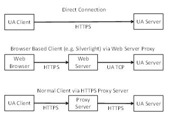
Figure 21 – Scenarios for the HTTPS Transport
In some scenarios, HTTPS communication will rely on an intermediary which is not trusted by the applications. If this is the case, then the HTTPS transport cannot be used to ensure security and the applications will have to establish a secure tunnel like a VPN before attempting any OPC UA related communication.
Applications which support the HTTPS transport shall support HTTP and TLS.
Some HTTPS implementations require that all Servers have a Certificate with a Common Name (CN) that matches the DNS name of the Server machine. This means that a Server with multiple DNS names will need multiple HTTPS certificates. If multiple Servers are on the same machine they may share HTTPS certificates. This means that ApplicationCertificates are not the same as HTTPS Certificates. Applications which use the HTTPS transport and require application authentication shall check application Certificates during the CreateSession/ActivateSession handshake.
HTTPS Certificates can be automatically generated; however, this will cause problems for Clients operating inside a restricted environment such as a web browser. Therefore, HTTPS certificates should be issued by an authority which is accepted by all web browsers which need to access the Server. The set of Certificate authorities accepted by the web browsers is determined by the organization that manages the Client machines. Client applications that are not running inside a web may use the trust list that is used for application Certificates.
A Server that is configured to use an HTTPS proxy shall have a mechanism to ensure that requests only come from that HTTPS proxy. The exact mechanism, such as binding to the loopback address, is implementation dependent.
HTTPS connections have an unpredictable lifetime. Therefore, Servers must rely on the AuthenticationToken passed in the RequestHeader to determine the identity of the Client. This means the AuthenticationToken shall be a randomly generated value with at least 32 bytes of data and HTTPS with signing and encryption shall always be used.
HTTPS allows Clients to have certificates; however, they are not required by the HTTPS transport. A Server shall allow Clients to connect without providing a Certificate during negotiation of the HTTPS connection.
HTTP 1.1 supports Message chunking where the Content-Length header in the request response is set to “chunked” and each chunk is prefixed by its size in bytes. All applications that support the HTTPS transport shall support HTTP chunking.
The URL scheme for endpoints using the HTTPS transport is ‘opc.https’. Note that ‘https’ is the generic URL scheme for the underlying transport. The opc prefix specifies that the endpoint accepts OPC UA messages as defined in this document.
Session-less Services (see OPC 10000-4) may be invoked via HTTPS POST.
The HTTP Authorization header is used to specify the UserIdentity used to determine what permissions are available to the caller. The Authorization header may specify a Basic token with a UserName/Password or a Bearer token (see RFC 6750) with an AccessToken provided by an AuthorizationService.
The HTTP Accept-Language header is used to specify the locales to use for the request. The locales are sorted based on their quality value and then by the order they appear in the header.
The Content-Type header in the HTTP request and response shall specify the DataEncoding of the message. Well known media types should be used to ensure interoperability with standard HTTP infrastructure. The application/opcua+uabinary media type is also defined, however, it is not registered with IANA and is only specified for backward compatibility.
Table 78 – HTTP Content-Type Header
|
Content-Type |
Description |
|
application/octet-stream |
The body is encoded using the OPC UA Binary DataEncoding defined in 5.2. |
|
application/soap+xml |
The body is encoded using the XML DataEncoding defined in 5.3. |
|
application/json |
The body is encoded using the OPC UA JSON Compact DataEncoding defined in 5.4. |
XML and JSON messages always use the UTF8 encoding. The charset parameter (i.e. ‘application/json; charset=utf-8’) may be appended to the media type to indicate this.
JSON messages may be compressed with RFC 1952. If compression is used the Content-Encoding HTTP Header is ‘gzip’.
This TransportProtocol implements the OPC UA Services using a SOAP request-response message pattern over an HTTPS connection.
The body of the HTTP Messages shall be a SOAP 1.2 Message (see SOAP Part 1). WS-Addressing headers are optional.
The OPC UA XML Encoding specifies a way to represent an OPC UA Message as an XML element. This element is added to the SOAP Message as the only child of the SOAP body element. If an error occurs in the Server while parsing the request body, the Server may return a SOAP fault or it may return an OPC UA error response.
The SOAP Action associated with an XML encoded request Message always has the form:
http://opcfoundation.org/UA/2008/02/Services.wsdl/<service name>
Where <service name> is the name of the OPC UA Service being invoked.
The SOAP Action associated with an XML encoded response Message always has the form:
http://opcfoundation.org/UA/2008/02/Services.wsdl/<service name>Response
All requests shall be HTTP POST requests. The Content-type shall be "application/soap+xml" and the charset and action parameters shall be specified. The charset parameter shall be "utf-8" and the action parameter shall be the URI for the SOAP action.
An example HTTP request header is:
POST /UA/SampleServer HTTP/1.1
Content-Type: application/soap+xml; charset="utf-8";
action="http://opcfoundation.org/UA/2008/02/Services.wsdl/Read"
Content-Length: nnnn
The action parameter appears on the same line as the Content-Type declaration.
An example request Message:
<s:Envelope xmlns:s="http://www.w3.org/2003/05/soap-envelope">
<s:Body>
<ReadRequest xmlns="http://opcfoundation.org/UA/2008/02/Types.xsd">
…
</ReadRequest>
</s:Body>
</s:Envelope>
An example HTTP response header is:
HTTP/1.1 200 OK
Content-Type: application/soap+xml; charset="utf-8";
action="http://opcfoundation.org/UA/2008/02/Services.wsdl/ReadResponse"
Content-Length: nnnn
The action parameter appears on the same line as the Content-Type declaration.
An example response Message:
<s:Envelope xmlns:s="http://www.w3.org/2003/05/soap-envelope">
<s:Body>
<ReadResponse xmlns="http://opcfoundation.org/UA/2008/02/Types.xsd">
…
</ReadResponse>
</s:Body>
</s:Envelope>
This TransportProtocol implements the OPC UA Services using an OPC UA Binary encoded Messages exchanged over an HTTPS connection.
Applications which support the HTTPS Profile shall support HTTP 1.1.
The body of the HTTP Messages shall be encoding using the OPC UA Binary DataEncoding. The Content-Type shall be "application/octet-stream".
An example HTTP request header is:
POST /UA/SampleServer HTTP/1.1
Content-Type: application/octet-stream
Content-Length: nnnn
An example HTTP response header is:
HTTP/1.1 200 OK
Content-Type: application/octet-stream
Content-Length: nnnn
The Message body is the request or response structure encoded as an ExtensionObject in OPC UA Binary. The Authorization header is only used for Session-less Service calls (see 1.1.55).
If the OPC UA Binary DataEncoding is used for a Session-less Service the HTTP request header is:
POST
/UA/SampleServer HTTP/1.1
Authorization : Bearer <base64-encoded-token-data>
Content-Type: application/octet-stream
Content-Length: nnnn
This TransportProtocol implements the OPC UA Services using JSON encoded Messages exchanged over an HTTPS connection.
Applications which support the HTTPS Profile shall support HTTP 1.1.
The body of the HTTP Messages shall be encoded using the OPC UA JSON DataEncoding and the Content-Type shall be ‘application/json’. If the message is compressed the Content-Encoding shall be ‘gzip’.
An example HTTP request header is:
POST
/UA/SampleServer HTTP/1.1
Authorization : Bearer <base64-encoded-token-data>
Content-Type: application/json
Content-Length: nnnn
An example HTTP response header is:
HTTP/1.1 200 OK
Content-Type: application/json
Content-Encoding: gzip
Content-Length: nnnn
This TransportProtocol sends OPC UA Connection Protocol messages over WebSockets.
WebSockets is a bi-directional protocol for communication via a web server which is commonly used by browser-based applications to allow the web server to asynchronously send information to the client. WebSockets uses the same default port as HTTP or HTTPS and initiates communication with an HTTP request. This makes it very useful in environments where firewalls limit traffic to the ports used by HTTP or HTTPS.
WebSockets use HTTP, however, in practice a WebSocket connection is only initiated with a HTTP GET request and the web server provides an HTTP response. After that exchange, all traffic uses the binary framing protocol defined by RFC 6455.
A Server that supports the WebSockets transport shall publish one or more Endpoints with the scheme ‘opc.wss’. The TransportProfileUri shall be one of the URIs for WebSockets transports defined in OPC 10000-7. The TransportProfileUri specifies the encoding and security protocol used to construct the OPC UA messages sent via the WebSocket.
The SecurityMode and SecurityPolicyUri of the Endpoint control the security applied to the messages sent via the WebSocket. This allows the messages to be secure even if the WebSocket connection is established via untrusted HTTPS proxies.
Figure 22 summarizes the complete process for establishing communication over a WebSocket.
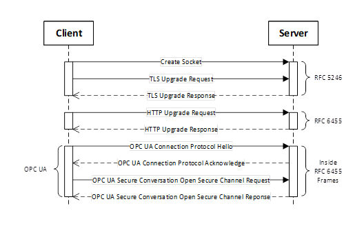
Figure 22 – Setting up Communication over a WebSocket
Figure 22 assumes the opcua+uacp sub-protocol (see 1.1.60). There is no SecureChannel negotiation when using opcua+json sub-protocol.
The default UserIdentity for any Session-less Service calls made over the WebSocket is specified by the opcua+token sub-protocol. It may also be used to determine if the Client is allowed to create a Session.
The WebSocket protocol allows clients to request that servers use specific sub-protocols with the “Sec-WebSocket-Protocol” header in the WebSocket handshake defined in RFC 6455. The sub-protocols defined by this document are shown in Table 79.
Table 79 – WebSocket Sub-Protocols
|
Sub-Protocol |
Description |
|
opcua+uacp |
Each WebSocket frame is a MessageChunk as defined in 1.1.42. After the WebSocket is created, the handshake described in 1.1.51 is used to negotiate the maximum size of the MessageChunk. The maximum size for a buffer needed to receive a WebSocket frame is the maximum length of a MessageChunk plus the maximum size for the WebSocket frame header. When using this sub-protocol, the payload in each frame is binary (OpCode 0x2 in RFC 6455). |
|
opcua+uajson |
Each WebSocket frame is a Message encoded using the JSON encoding described in 1.1.31. There is no mechanism to negotiate the maximum frame size. If the receiver encounters a frame that exceeds its internal limits it shall close the WebSocket connection and provide a 1009 status code as described in RFC 6455. This sub-protocol is not recommended. The opcua+openapi sub-protocol should be used instead. |
|
opcua+openapi |
Each WebSocket frame is a ServiceMessageEnvelope described in G.3. There is no mechanism to negotiate the maximum frame size. If the receiver encounters a frame that exceeds its internal limits it shall close the WebSocket connection and provide a 1009 status code as described in RFC 6455. When using this sub-protocol, the payload in each frame is text (OpCode 0x1 in RFC 6455) if the frame contains UTF8 encoded JSON. If the frame contains JSON compressed with RFC 1952 then the frame is binary (OpCode 0x2 in RFC 6455). |
|
opcua+openapi+<accesstoken> |
This sub-protocol is only used in addition to the opcua+openapi sub-protocol.and specifies the default UserIdentity for all Requests sent over the WebSocket. The <accesstoken> is the JSON WebToken (see 1.1.39) and is normally passed in the HTTPS Authentication header. Using a sub-protocol to provide an AccessToken is a widely used design pattern needed to deal with limitations of common WebSocket implementations. |
Each WebSocket sub-protocol defined has a TransportProfileUri defined in OPC 10000-7.
The Client shall request a sub-protocol. If the Server does not support the sub-protocol requested by the Client, the Client shall close the connection and report an error.
The WebSockets protocol requires that the Server have a Certificate, however, the Client may have a Certificate. The Server Certificate should have the domain name as the common name component of the subject name however, Clients that are able to override the Certificate validation procedure can choose to accept Certificates with a domain mismatch.
When using the WebSockets transport from a web browser the browser environment may impose additional restrictions. For example, the web browser may require the Server have a valid TLS Certificate that is issued by CA that is installed in the Trust List for the web browser. To support these Clients, a Server may use a TLS Certificate that does not conform to the requirements for an ApplicationInstance Certificate. In these cases, the TLS Certificate is only used for TLS negotiation and the Server shall use a valid ApplicationInstance Certificate for other interactions that require one. Servers shall allow administrators to specify a Certificate for use with TLS that is different from the ApplicationInstance Certificate.
Clients running in a browser environment specify the ‘Origin’ HTTP header during the WebSocket upgrade handshake. Servers should return the ‘Access-Control-Allow-Origin’ to indicate that the connection is allowed.
Any Client that does not run in a web browser environment and supports the WebSockets transport shall accept OPC UA ApplicationInstance Certificate as the TLS Certificate provided the correct domain is specified in the subjectAltName field.
A Client may use its ApplicationInstance Certificate as the TLS Certificate and Servers shall accept those Certificates if they are valid according to the OPC UA Certificate validation rules.
Some operating systems will not give the application any control over the set of algorithms that TLS will negotiate. In some cases, this set will be based on the needs of web browsers and will not be appropriate for the needs of an OPC UA Application. If this is a concern, applications should use OPC UA Secure Conversation in addition to TLS.
Clients that support the WebSocket transport shall support explicit configuration of an HTTPS proxy. When using an HTTPS proxy, the Client shall first send an HTTP CONNECT message (see HTTP) before starting the WebSocket protocol handshake. Note that explicit HTTPS proxies allow for man-in-the-middle attacks. This threat may be mitigated by using OPC UA Secure Conversation in addition to TLS.
The Local Discovery Server (LDS) is an OPC UA Server that implements the Discovery Service Set defined in OPC 10000-4. If an LDS is installed on a machine, it shall use one or more of the well-known addresses defined in Table 80.
Table 80 – Well known addresses for Local Discovery Servers
|
Transport Mapping |
URL |
Notes |
|
OPC UA TCP |
opc.tcp://localhost:4840/UADiscovery |
|
|
OPC UA WebSockets |
opc.wss://localhost:443/UADiscovery |
|
|
OPC UA HTTPS |
opc.https://localhost:443/UADiscovery |
|
OPC UA applications that make use of the LDS shall allow administrators to change the well-known addresses used within a system.
The Endpoint used by Servers to register with the LDS shall be the base address with the path “/registration” appended to it (e.g. http://localhost/UADiscovery/registration). OPC UA Servers shall allow administrators to configure the address to use for registration.
Each OPC UA Server application implements the Discovery Service Set. If the OPC UA Server requires a different address for this Endpoint, it shall create the address by appending the path “/discovery” to its base address.
The normative contract for the OPC UA Binary Encoded Messages is an OPC Binary Schema. This file defines the structure of all types and Messages. The syntax for an OPC Binary Type Schema is described in OPC 10000-3. This schema captures normative names for types and their fields as well the order the fields appear when encoded. The data type of each field is also captured.
The normative contract for the OPC UA XML encoded Messages is an XML Schema. This file defines the structure of all types and Messages. This schema captures normative names for types and their fields as well the order the fields appear when encoded. The data type of each field is also captured.
The normative contract for Message sent via the SOAP/HTTP TransportProtocol is a WSDL that includes XML Schema for the OPC UA XML encoded Messages. It also defines the port types for OPC UA Servers and DiscoveryServers.
Links to the WSDL and XML Schema files can be found in Annex D.
Annex F defines the schema to be used for Information Models.
Annex B defines the OPC UA NodeSet
Annex A defines constants for Attribute Ids, Status Codes and numeric NodeIds
Annex C defines the binary encoding for all DataTypes and Messages
Annex E defines a schema for security settings
Annex A
(normative)
Constants
Table A.1 shows Identifiers assigned to Attributes
Table A.1 – Identifiers assigned to Attributes
|
Attribute |
Identifier |
|
NodeId |
1 |
|
NodeClass |
2 |
|
BrowseName |
3 |
|
DisplayName |
4 |
|
Description |
5 |
|
WriteMask |
6 |
|
UserWriteMask |
7 |
|
IsAbstract |
8 |
|
Symmetric |
9 |
|
InverseName |
10 |
|
ContainsNoLoops |
11 |
|
EventNotifier |
12 |
|
Value |
13 |
|
DataType |
14 |
|
ValueRank |
15 |
|
ArrayDimensions |
16 |
|
AccessLevel |
17 |
|
UserAccessLevel |
18 |
|
MinimumSamplingInterval |
19 |
|
Historizing |
20 |
|
Executable |
21 |
|
UserExecutable |
22 |
|
DataTypeDefinition |
23 |
|
RolePermissions |
24 |
|
UserRolePermissions |
25 |
|
AccessRestrictions |
26 |
|
AccessLevelEx |
27 |
Clause A.2 defines the numeric identifiers for all of the StatusCodes defined by the OPC UA Specification. The identifiers are specified in a UTF8 encoded CSV file with the following syntax:
<SymbolName>, <Code>, <Description>
Where the SymbolName is the literal name for the error code that appears in the specification and the Code is the hexadecimal value for the StatusCode (see OPC 10000-4). The severity associated with a particular code is specified by the prefix (Good, Uncertain or Bad).
The CSV released with this version of the standards can be found here:
https://reference.opcfoundation.org/files/StatusCode.csv?u=http://opcfoundation.org/UA/&v=1.05.04
NOTE The latest CSV that is compatible with this version of the standard can be found here:
https://reference.opcfoundation.org/files/StatusCode.csv?u=http://opcfoundation.org/UA/
Clause A.3 defines the numeric identifiers for all of the numeric NodeIds defined by the OPC UA Specification. The identifiers are specified in a UTF8 encoded CSV file. The syntax is informative and provided to assist developers of tools. The UANodeSet is the normative source for all identifiers.
Each line in the CSV file has the following fields:
<SymbolName>, <Identifier>, <NodeClass>
Where the SymbolName is either the BrowseName of a Type Node or the BrowsePath for an Instance Node that appears in the specification and the Identifier is numeric value for the NodeId. Each SymbolName is unique within the CSV file.
The BrowsePath for an instance Node may be constructed by appending the BrowseName of the instance Node to BrowseName for the containing instance or type. A ‘_’ character is used to separate each BrowseName in the path. For example, OPC 10000-5 defines the ServerType ObjectType Node which has the NamespaceArray Property. The SymbolName for the NamespaceArray InstanceDeclaration within the ServerType declaration is: ServerType_NamespaceArray. OPC 10000-5 also defines a standard instance of the ServerType ObjectType with the BrowseName ‘Server’. The BrowseName for the NamespaceArray Property of the standard Server Object is: Server_NamespaceArray.
When Nodes do not have a parent that allows the creation of unique SymbolNames then an ad hoc convention is adopted. For example, DataTypeEncoding Nodes have the form:
<DataTypeName>_Encoding_<BrowseName>
The NamespaceUri for all NodeIds defined is http://opcfoundation.org/UA/
The CSV released with this version of the standards can be found here:
https://reference.opcfoundation.org/files/NodeIds.csv?u=http://opcfoundation.org/UA/&v=1.05.04
NOTE The latest CSV that is compatible with this version of the standard can be found here:
https://reference.opcfoundation.org/files/NodeIds.csv?u=http://opcfoundation.org/UA/
Globally defined media types are assigned by IANA. This clause lists the media types that have been assigned by IANA to document formats defined by OPC UA.
Table A.2 has media types assigned to OPC UA document formats.
Table A.2 – Media Types Assigned to OPC UA Document Formats
|
Media Type |
Description |
|
application/opc-nodeset+xml |
An XML document that conforms to the XML
schema defined in Annex F. |
Annex B
(normative)
OPC UA NodeSet
The OPC UA NodeSet includes the complete Information Model defined in this document. It follows the XML Information Model schema syntax defined in Annex F and can thus be read and processed by a computer program.
The complete Information Model Schema for this version of this document (including any amendments and errata) can be found here:
NOTE The latest Information Model schema that is compatible with this version of this document can be found here:
The complete Information Model Schema includes many types which are only used in Service Requests and Responses and should not be used by Servers to populate their Address Space.
The subset of the Information Model Schema for this version of this document (including any amendments and errata) that is used for creating Address Spaces can be found here:
NOTE The latest Information Model schema that is compatible with this version of this document can be found here:
https://reference.opcfoundation.org/files/Opc.Ua.NodeSet2.xml?u=http://opcfoundation.org/UA/
Annex C
(normative)
Type declarations for the OPC UA native Mapping
Note: Deprecated in Version 1.05.
Annex D
(normative)
WSDL for the XML Mapping
Clause D.1 defines the XML Schema for all DataTypes and Messages defined in the OPC UA namespace
The XML Schema released with this version of this document can be found here:
https://reference.opcfoundation.org/files/Opc.Ua.Types.xsd?u=http://opcfoundation.org/UA/&v=1.05.04
NOTE The latest file that is compatible with this version of this document can be found here:
https://reference.opcfoundation.org/files/Opc.Ua.Types.xsd?u=http://opcfoundation.org/UA/
Clause D.2 defines the WSDL Operations and Port Types for all Services defined in OPC 10000-4.
The WSDL released with this version of this document can be found here:
http://www.opcfoundation.org/UA/schemas/1.05/Opc.Ua.Services.wsdl
NOTE The latest file that is compatible with this version of this document can be found here:
http://opcfoundation.org/UA/2008/02/Services.wsdl
This WSDL imports the XML Schema defined in D.1.
Clause D.3 defines the WSDL Bindings for all Services defined in OPC 10000-4.
The WSDL released with this version of this document can be found here:
http://www.opcfoundation.org/UA/schemas/1.05/Opc.Ua.Endpoints.wsdl
NOTE The latest file that is compatible with this version of this document can be found here:
http://opcfoundation.org/UA/2008/02/Endpoints.wsdl
This WSDL imports the WSDL defined in D.2.
Annex E
(informative)
Security settings management
All OPC UA applications support security; and this means that Administrators need to configure the security settings for the OPC UA application. Clause E.1 describes an XML Schema which can be used to read and update the security settings for an OPC UA application. This schema provides a reference for application developers adding support for security configuration to their applications.
The XML Schema released with this version of the standards can be found here:
http://www.opcfoundation.org/UA/schemas/1.05/SecuredApplication.xsd
NOTE The latest file that is compatible with this version of this specification can be found here:
http://opcfoundation.org/UA/2011/03/SecuredApplication.xsd
The SecuredApplication schema can be supported in two ways:
1) Providing an XML configuration file that can be edited directly;
3) Providing an import/export utility that can be run as required;
If the application supports direct editing of an XML configuration file, then that file has exactly one element with the local name ‘SecuredApplication’ and URI equal to the SecuredApplication schema URI. A third-party configuration utility is able to parse the XML file, read and update the ‘SecuredApplication’ element. The administrator ensures that only authorized administrators can update this file. The following is an example of a configuration that can be directly edited:
<s1:SampleConfiguration xmlns:s1="http://acme.com/UA/Sample/Configuration.xsd">
<ApplicationName>ACME UA Server</ApplicationName>
<ApplicationUri>urn:myfactory.com:Machine54:ACME UA Server</ApplicationUri>
<!-- any number of application specific elements -->
<SecuredApplication xmlns="http://opcfoundation.org/UA/2011/03/SecuredApplication.xsd">
<ApplicationName>ACME UA Server</ApplicationName>
<ApplicationUri>urn:myfactory.com:Machine54:ACME UA Server</ApplicationUri>
<ApplicationType>Server_0</ApplicationType>
<StoreType>Windows</StoreType>
<StorePath>LocalMachine\My</StorePath>
<SubjectName>ACME UA Server</SubjectName>
<!-- any number of application specific elements -->
<DisableHiResClock>true</DisableHiResClock>
If an application provides an import/export utility, then the import/export file is a document that conforms to the SecuredApplication schema. The administrator ensures that only authorized administrators can run the utility. The following is an example of a file used by an import/export utility:
<?xml version="1.0" encoding="utf-8" ?>
<SecuredApplication xmlns="http://opcfoundation.org/UA/2011/03/SecuredApplication.xsd">
<ApplicationName>ACME UA Server</ApplicationName>
<ApplicationUri>urn:myfactory.com:Machine54:ACME UA Server</ApplicationUri>
<ApplicationType>Server_0</ApplicationType>
<ConfigurationMode>urn:acme.com:ACME Configuration Tool</ConfigurationMode>
<LastExportTime>2011-03-04T13:34:12Z</LastExportTime>
<ExecutableFile>%ProgramFiles%\ACME\Bin\ACME UA Server.exe</ExecutableFile>
<StoreType>Windows</StoreType>
<StorePath>LocalMachine\My</StorePath>
<SubjectName>ACME UA Server</SubjectName>
<StoreType>Windows</StoreType>
<StorePath>LocalMachine\UA applications</StorePath>
<!-- Offline CRL Checks by Default -->
<ValidationOptions>16</ValidationOptions>
<SubjectName>CN=MyFactory CA</SubjectName>
<!-- Online CRL Check for this CA -->
<ValidationOptions>32</ValidationOptions>
<StoreType>Directory</StoreType>
<StorePath>%CommonApplicationData%\OPC Foundation\RejectedCertificates</StorePath>
The SecuredApplication element specifies the security settings for an application. The elements contained in a SecuredApplication are described in Table E.1.
When an instance of a SecuredApplication is imported into an application the application updates its configuration based on the information contained within it. If unrecoverable errors occur during import an application does not make any changes to its configuration and report the reason for the error.
The mechanism used to import or export the configuration depends on the application. Applications ensure that only authorized users are able to access this feature.
The SecuredApplication element may reference X.509 v3 Certificates which are contained in physical stores. Each application needs to decide whether it uses shared physical stores which the administrator can control directly by changing the location or private stores that can only be accessed via the import/export utility. If the application uses private stores, then the contents of these private stores are copied to the export file during export. If the import file references shared physical stores, then the import/export utility copies the contents of those stores to the private stores.
The import/export utility does not export private keys. If the administrator wishes to assign a new public-private key to the application the administrator places the private key in a store where it can be accessed by the import/export utility. The import/export utility is then responsible for ensuring it is securely moved to a location where the application can access it.
Table E.1 – SecuredApplication
The CertificateIdentifier element describes an X.509 v3 Certificate. The Certificate can be provided explicitly within the element or the element can specify the location of the CertificateStore that contains the Certificate. The elements contained in a CertificateIdentifier are described in Table E.2.
Table E.2 – CertificateIdentifier
A "Windows" StoreType specifies a Windows Certificate store.
The syntax of the StorePath has the form:
[\\HostName\]StoreLocation[\(ServiceName | UserSid)]\StoreName
HostName – the name of the machine where the store resides.
StoreLocation – one of LocalMachine, CurrentUser, User or Service
ServiceName – the name of a Windows Service.
UserSid – the SID for a Windows user account.
StoreName – the name of the store (e.g. My, Root, Trust, CA, etc.).
Examples of Windows StorePaths are:
\\MYPC\Service\My UA Server\UA applications
A "Directory" StoreType specifies a directory on disk which contains files with DER encoded Certificates. The name of the file is the CertificateDigest for the Certificate. Only public keys may be placed in a "Directory" Store. The StorePath is an absolute file system path with a syntax that depends on the operating system.
If a "Directory" store contains a ‘certs’ subdirectory, then it is presumed to be a structured store with the subdirectories described in Table E.3.
Table E.3 – Structured directory store
Each Certificate is uniquely identified by its Thumbprint. The SubjectName or the distinguished SubjectName may be used to identify a Certificate to a human; however, they are not unique. The SubjectName may be specified in conjunction with the Thumbprint or the RawData. If there is an inconsistency between the information provided, then the CertificateIdentifier is invalid. Invalid CertificateIdentifiers are handled differently depending on where they are used.
It is recommended that the SubjectName always be specified.
A Certificate revocation list (CRL) contains a list of certificates issued by a CA that are no longer trusted. These lists should be checked before an application can trust a Certificate issued by a trusted CA. The format of a CRL is defined by RFC 5280.
Offline CRLs are placed in a local Certificate store with the Issuer Certificate. Online CRLs may exist but the protocol depends on the system. An online CRL is identified by a URL.
E.4 CertificateStoreIdentifier
The CertificateStoreIdentifier element describes a physical store containing X.509 v3 Certificates. The elements contained in a CertificateStoreIdentifier are described in Table E.4.
Table E.4 – CertificateStoreIdentifier
All Certificates are placed in a physical store which can be protected from unauthorized access. The implementation of a store can vary and will depend on the application, development tool or operating system. A Certificate store may be shared by many applications on the same machine.
Each Certificate store is identified by a StoreType and a StorePath. The same path on different machines identifies a different store.
The CertificateList element is a list of Certificates. The elements contained in a CertificateList are described in Table E.5.
Table E.5 – CertificateList
E.6 CertificateValidationOptions
The CertificateValidationOptions control the process used to validate a Certificate. Any Certificate can have validation options associated. If none are specified, the ValidationOptions for the store or list containing the Certificate are used. The possible options are shown in Table E.6. Note that suppressing any validation step can create security risks which are discussed in more detail in OPC 10000-2. An audit log entry is created if any error is ignored because a validation option is suppressed.
Table E.6 – CertificateValidationOptions
Annex F
(normative)
Information Model XML Schema
Information Model developers define standard AddressSpaces which are implemented by many Servers. There is a need for a standard syntax that Information Model developers can use to formally define their models in a form that can be read by a computer program. Annex F defines an XML-based schema for this purpose.
The XML Schema released with this version of the standards can be found here:
https://reference.opcfoundation.org/files/UANodeSet.xsd?u=http://opcfoundation.org/UA/&v=1.05.04
NOTE The latest file that is compatible with this version of the standards can be found here:
https://reference.opcfoundation.org/files/UANodeSet.xsd?u=http://opcfoundation.org/UA/
The schema document is the formal definition. The description in Annex F only discusses details of the semantics that cannot be captured in the schema document. Types which are self-describing are not discussed.
This schema can also be used to serialize (i.e. import or export) an arbitrary set of Nodes in the Server Address Space. This serialized form can be used to save Server state for use by the Server later or to exchange with other applications (e.g. to support offline configuration by a Client).
This schema only defines a way to represent the structure of Nodes. It is not intended to represent the numerous semantic rules which are defined in other parts of the OPC UA specification. Consumers of data serialized with this schema need to handle inputs that conform to the schema, however, do not conform to the OPC UA specification because of one or more semantic rule violations.
There are cases where an Information Model defines Nodes such as standard Properties which can be attached to many different Nodes. These Nodes are represented in the UANodeSet as Nodes which are not a target of any reference that would make them visible in an AddressSpace.
The tables defining the DataTypes in the specification have field names starting with a lowercase letter. The first letter shall be converted to upper case when the field names are formally defined in a UANodeSet.
Every UANodeSet that defines DataTypes has associated schema files that define how to serialize the DataTypes using the UA Binary Encoding (5.2) and the UA XML Encoding (5.3). The XML schema file may be referenced by the UANodeSet if it includes Variable Values (F.8) for one or more of the DataTypes defined in the UANodeSet. The namespace URI assigned to the XML schema is set by the tool that generated it. The URI for the XML schema for OPC UA DataTypes is http://opcfoundation.org/UA/2008/02/Types.xsd.
The UANodeSet is the root of the document. It defines a set of Nodes, their Attributes and References. References to Nodes outside of the document are allowed.
The structure of a UANodeSet is shown in Table F.1.
Table F.1 – UANodeSet
|
Element |
Type |
Description |
|
NamespaceUris |
UriTable |
A list of NamespaceUris used in the UANodeSet. This array shall have at least one entry which is equal to the ModelUri for each entry in the Models array. |
|
ServerUris |
UriTable |
A list of ServerUris used in the UANodeSet. |
|
Models |
ModelTableEntry [] |
A list of models that are defined in the UANodeSet along with any dependencies these models have. |
|
ModelUri |
String |
The URI for the model. This URI shall be one of the entries in the NamespaceUris table. |
|
String |
The URI for the XML schema namespace used to serialize values of the DataTypes defined by the Model. The field is required if DataTypes are defined in the UANodeSet. The UA XML Encoding (5.3) rules implicitly define the XML schema for any DataType described by a DataTypeDefinition (F.12). |
|
|
Version |
String |
The version of the model defined in the UANodeSet. This is a human readable string and not intended for programmatic comparisons. |
|
PublicationDate |
DateTime |
When the model was published. This value is used for comparisons if the Model is defined in multiple UANodeSet files when the ModelVersion is not provided. |
|
ModelVersion |
VersionString |
The version of the UANodeSet expressed as a string which conforms to the syntax defined in the SemVer specification. The comparison rules from the specification are used to determine which UANodeSet precedes another. When the ModelVersion is specified in two UANodeSets, the PublicationDate is not used when comparing the UANodeSets. When the ModelVersion is specified in only one UANodeSet, the PublicationDate is used when comparing the UANodeSets and the ModelVersion is ignored. The ModelVersion is optional in previously released UANodeSets and it is required in all future UANodeSets. |
|
RolePermissions |
RolePermission [] |
The list of default RolePermissions for all Nodes in the model. |
|
AccessRestrictions |
AccessRestriction |
The default AccessRestrictions that apply to all Nodes in the model. The default value is 0. |
|
RequiredModels |
ModelTableEntry [] |
A list of dependencies for the model. If the model requires a minimum version the PublicationDate shall be specified. Tools which attempt to resolve these dependencies may accept any PublicationDate after this date. The RolePermission and AccessRestrictions elements shall not be specified for any entry in this list. |
|
Aliases |
AliasTable |
A list of UANodeSet aliases used in the UANodeSet. |
|
Extensions |
xs:any [] |
An element containing a list of vendor defined extensions to the UANodeSet. |
|
LastModified |
DateTime |
The last time a document was modified. |
|
<choice> |
UAObject UAVariable UAMethod UAView UAObjectType UAVariableType UADataType UAReferenceType |
The Nodes in the UANodeSet. |
The NamespaceUris is a list of URIs for namespaces used in the UANodeSet. The NamespaceIndexes used in NodeId, ExpandedNodeIds and QualifiedNames identify an element in this list. The first index is always 1 (0 is always the OPC UA namespace).
The ServerUris is a list of URIs for Servers referenced in the UANodeSet. The ServerIndex in ExpandedNodeIds identifies an element in this list. The first index is always 1 (0 is always the current Server).
The Models element specifies the Models which are formally defined by the UANodeSet. It includes version information as well as information about any dependencies which the model may have. If a Model is defined in the UANodeSet then the file shall also define an instance of the NamespaceMetadataType ObjectType. See OPC 10000-5 for more information. Following the references in the RequiredModels field shall not result in circular dependencies.
The XML schema file associated with a UANodeSet shall have an XML annotation with a Model element that identifies the associated UANodeSet with the form:
<xs:annotation>
<xs:appinfo>
<ua:Model
ModelUri="<model-uri>"
ModelVersion="<model-version>"
PublicationDate="<publication-date>"
/>
</xs:appinfo>
</xs:annotation>
Where:
· <model-uri> is the URI of the associated UANodeSet;
· <model-version> is the SemVer of the associated UANodeSet;
· <publication-date> is the date the associated UANodeSet was published.
When NodeSets are normative documents for a specification, they can include Nodes, such as unattached Properties, that exist only to formally define elements of the specification. For example, the base NodeSet for this specification includes an unattached Property Node called “NodeVersion” which can be added to any Node. The Node in the NodeSet defines the BrowseName, DataType and ValueRank.
The UANodeSet aliases are a list of string substitutions for NodeIds. UANodeSet aliases can be used to make the file more readable by allowing a string like ‘HasProperty’ in place of a numeric NodeId (i=46). Aliases are optional. Aliases may only be used in fields defined in this Annex that have the NodeId type such as ParentNodeId (F.7) or DataType (F.8). Fields with the Variant type shall not contain UANodeSet aliases.
The Extensions are free form XML data that can be used to attach vendor defined data to the UANodeSet.
A UANode is an abstract base type for all Nodes. It defines the base set of Attributes and the References. There are subtypes for each NodeClass defined in OPC 10000-4. Each of these subtypes defines XML elements and attributes for the OPC UA Attributes specific to the NodeClass. The fields in the UANode type are defined in Table F.2.
Table F.2 – UANode
|
Element |
Type |
Description |
|
NodeId |
NodeId |
A NodeId serialized as a String. The syntax of the serialized String is defined in 5.3.1.10. |
|
BrowseName |
QualifiedName |
A QualifiedName serialized as a String with the form: <namespace index>:<name> Where the NamespaceIndex refers to the NamespaceUris table. |
|
SymbolicName |
String |
A symbolic name for the Node that can be used as a class/field name in auto generated code. It should only be specified if the BrowseName cannot be used for this purpose. This field does not appear in the AddressSpace and is intended for use by design tools. Only letters, digits or the underscore (‘_’) are permitted and the first character shall be a letter. |
|
WriteMask |
WriteMask |
The value of the WriteMask Attribute. |
|
UserWriteMask |
WriteMask |
Not used. Kept in schema for backward compatibility. |
|
AccessRestrictions |
AccessRestriction |
The AccessRestrictions that apply to the Node. This attribute is optional. If not specified the AccessRestrictions for the Model are applied. |
|
DisplayName |
LocalizedText [] |
A list of DisplayNames for the Node in different locales. There shall be only one entry per locale. |
|
Description |
LocalizedText [] |
The list of the Descriptions for the Node in different locales. There shall be only one entry per locale. |
|
Category |
String [] |
A list of ConformanceUnits associated with the Node. The ConformanceUnits are specified by the authors of the UANodeSet and allow users of the UANodeSet to exclude Nodes based on a selection of ConformanceUnits. When an UAInstance has the ParentNodeId specified, the UAInstance inherits the ConformanceUnits from its parent in addition to any ConformanceUnits explicitly specified on the instance. |
|
Documentation |
String |
Additional non-localized documentation for use by tools that create/edit UANodeSet files. |
|
ReleaseStatus |
ReleaseStatus |
An enumeration specifying the release status for the UANode. Valid values are: Released: The type is released. Changes require errata; Draft: The type is draft and subject to change; Deprecated: The type should not be used; This field is for use on UATypes and static UAInstances. The field shall not be specified for UAInstances that are InstanceDeclarations. |
|
References |
Reference [] |
The list of References for the Node. |
|
RolePermissions |
RolePermission [] |
The list of RolePermissions for the Node. If the list is not specified or has zero length the default RolePermissions from the Model are used unless HasNoPermissions is TRUE. |
|
HasNoPermissions |
Boolean |
If TRUE, the UANode has no RolePermissions and the contents of the RolePermissions array and the default RolePermissions for the model are ignored. The default value is FALSE. |
|
Extensions |
xs:any [] |
An element containing a list of vendor defined extensions to the UANode. |
The Extensions are free form XML data that can be used to attach vendor defined data to the UANode.
Array values are denoted with [], however, in the XML Schema arrays are mapped to a complex type starting with the ‘ListOf’ prefix.
A UANodeSet is expected to contain many UANodes which reference each other. Tools that create UANodeSets should not add Reference elements for both directions in order to minimize the size of the XML file. Tools that read the UANodeSets shall automatically add reverse references unless reverse references are not appropriate given the ReferenceType semantics. HasTypeDefinition and HasModellingRule are two examples where it is not appropriate to add reverse references.
When a UANodeSet is the normative definition for the Nodes defined by a specification then the RolePermissions are the minimum requirements. Implementors may add additional Roles that have privileges equivalent to the Roles specified, however, they may not make the Node more accessible. For example, Anonymous or AuthenticatedUser Roles shall not be granted more access to the Node than is specified in this field.
Similarly, the AccessRestrictions are the minimum required. For example, a Node that has the EncryptionRequired AccessRestriction specified shall not have that restriction removed, however, additional restrictions may be added by the implementor. Note, that a UANodeSet represents a collection of Nodes in an address space. This implies that any instances shall include the fully inherited InstanceDeclarationHierarchy as defined in OPC 10000-3.
The Reference type specifies a Reference for a Node. The Reference can be forward or inverse. Only one direction for each Reference needs to be in a UANodeSet. The other direction shall be added automatically during any import operation. The fields in the Reference type are defined in Table F.3.
Table F.3 – Reference
|
Element |
Type |
Description |
|
NodeId |
NodeId |
The NodeId of the target of the Reference serialized as a String. The syntax of the serialized String is defined in 5.3.1.11 (ExpandedNodeId). This value can be replaced by an Alias. |
|
ReferenceType |
NodeId |
The NodeId of the ReferenceType serialized as a String. The syntax of the serialized String is defined in 5.3.1.10 (NodeId). This value can be replaced by an Alias. |
|
IsForward |
Boolean |
If TRUE, the Reference is a forward reference. |
The RolePermission type specifies the Permissions granted to Role for a Node. The fields in the RolePermission type are defined in Table F.4.
Table F.4 – RolePermission
|
Element |
Type |
Description |
|
NodeId |
NodeId |
The NodeId of the Role which has the Permissions. |
|
Permissions |
UInt32 |
A bitmask specifying the Permissions granted to the Role. The bitmask values the Permissions bits defined in OPC 10000-3. |
A UAType is a subtype of the UANode defined in F.3. It is the base type for the types defined in Table F.5.
Table F.5 – UANodeSet Type Nodes
|
Subtype |
Description |
|
UAObjectType |
Defines an ObjectType Node as described in OPC 10000-3. |
|
UAVariableType |
Defines a VariableType Node as described in OPC 10000-3. |
|
UADataType |
Defines a DataType Node as described in OPC 10000-3. |
|
UAReferenceType |
Defines a ReferenceType Node as described in OPC 10000-3. |
A UAInstance is a subtype of the UANode defined in F.3. It is the base type for the types defined in Table F.6. The fields in the UAInstance type are defined in Table F.7. Subtypes of UAInstance which have fields in addition to those defined in OPC 10000-3 are described in detail below.
Table F.6 – UANodeSet Instance Nodes
|
Subtype |
Description |
|
UAObject |
Defines an Object Node as described in OPC 10000-3. |
|
UAVariable |
Defines a Variable Node as described in OPC 10000-3. |
|
UAMethod |
Defines a Method Node as described in OPC 10000-3. |
|
UAView |
Defines a View Node as described in OPC 10000-3. |
Table F.7 – UAInstance
|
Element |
Type |
Description |
|
All of the fields from the UANode type described in F.3. |
||
|
ParentNodeId |
NodeId |
This field shall be specified for all InstanceDeclarations and shall reference a UANode which is the source of a HierarchicalReference to the Node. |
|
DesignToolOnly |
Boolean |
If TRUE the instance is a placeholder for use by design tools and does not appear in the AddressSpace. For example, well-known Properties or Objects. Only UAObject and UAVariable Nodes may have DesignToolOnly is TRUE. If DesignToolOnly is TRUE, the ParentNodeId shall not be specified and the UAInstance may not be the target of references from other Nodes and may not be the ParentNodeId for other instances. This implies that child Nodes, even Mandatory ones, are not added to the Node. The HasTypeDefinition reference shall be specified. |
A UAVariable is a subtype of the UAInstance defined in. It represents a Variable Node. The fields in the UAVariable type are defined in Table F.8.
Table F.8 – UAVariable
|
Element |
Type |
Description |
|
All of the fields from the UAInstance type described in F.7. |
||
|
Value |
Variant |
The Value of the Node encoding using the UA XML wire encoding defined in 5.3. If a Value is not provided and a UANodeSet is used to initialize a Server AddressSpace then the Server shall report a StatusCode of Bad_NoValue or choose a default Value consistent with the DataType and ValueRank. |
|
Translation |
TranslationType [] |
A list of translations for the Value if the Value is a LocalizedText or a structure containing LocalizedTexts. This field may be omitted. If the Value is an array the number of elements in this array shall match the number of elements in the Value. Extra elements are ignored. If the Value is a scalar, then there is one element in this array. If the Value is a structure, then each element contains translations for one or more fields identified by a name. See the TranslationType for more information. |
|
DataType |
NodeId |
The data type of the value. |
|
ValueRank |
ValueRank |
The value rank. If not specified, the default value is -1 (Scalar). |
|
ArrayDimensions |
ArrayDimensions |
The number of dimensions in an array value. |
|
AccessLevel |
AccessLevel |
The access level. This value is a UInt32 that includes all of the bits exposed by the AccessLevelEx. Servers which do not support the additional bits in AccessLevelEx should ignore them. |
|
UserAccessLevel |
AccessLevel |
Not used. Kept in schema for backward compatibility. |
|
MinimumSamplingInterval |
Duration |
The minimum sampling interval. |
|
Historizing |
Boolean |
Whether history is being archived. |
A UAMethod is a subtype of the UAInstance defined in F.7. It represents a Method Node. The fields in the UAMethod type are defined in Table F.9.
Table F.9 – UAMethod
|
Element |
Type |
Description |
|
All of the fields from the UAInstance type described in F.7. |
||
|
MethodDeclarationId |
NodeId |
May be specified for Method Nodes that are a target of a HasComponent reference from a single Object Node. It is the NodeId of the UAMethod with the same BrowseName contained in the TypeDefinition associated with the Object Node. If the TypeDefinition overrides a Method inherited from a base ObjectType then this attribute shall reference the Method Node in the subtype. |
|
Executable |
Boolean |
Indicates that the Method is executable. The default value is TRUE. |
|
UserExecutable |
Boolean |
Not used. Kept in schema for backward compatibility. |
|
ArgumentDescription |
UAMethodArgument [] |
A list of Descriptions for the Method Node Arguments. Each entry has a Name which uniquely identifies the Argument that the Descriptions apply to. There shall only be one entry per Name. Each entry also has a list of Descriptions for the Argument in different locales. There shall be only one entry per locale per Argument. |
A TranslationType contains additional translations for LocalizedTexts used in the Value of a Variable. The fields in the TranslationType are defined in Table F.10. If multiple Arguments existed there would be a Translation element for each Argument.
The type can have two forms depending on whether the Value is a LocalizedText or a Structure containing LocalizedTexts. If it is a LocalizedText is contains a simple list of translations. If it is a Structure, it contains a list of fields which each contain a list of translations. Each field is identified by a Name which is unique within the structure. The mapping between the Name and the Structure requires an understanding of the Structure encoding. If the Structure field is encoded as a LocalizedText with UA XML, then the name is the unqualified path to the XML element where names in the path are separated by ‘/’. For example, a structure with a nested structure containing a LocalizedText could have a path like “Server/ApplicationName”.
The following example illustrates how translations for the Description field in the Argument Structure are represented in XML:
<Value>
<ListOfExtensionObject xmlns="http://opcfoundation.org/UA/2008/02/Types.xsd">
<ExtensionObject>
<TypeId>
<Identifier>i=297</Identifier>
</TypeId>
<Body>
<Argument>
<Name>ConfigData</Name>
<DataType>
<Identifier>i=15</Identifier>
</DataType>
<ValueRank>-1</ValueRank>
<ArrayDimensions />
<Description>
<Text>[English Translation for Description]</Text>
</Description>
</Argument>
</Body>
</ExtensionObject>
</ListOfExtensionObject>
</Value>
<Translation>
<Field Name="Description">
<Text Locale="de-DE">[German Translation for Description]</Text>
<Text Locale="fr-FR">[French Translation for Description]</Text>
</Field>
</Translation>
If multiple Arguments existed there would be a Translation element for each Argument.
Table F.10 – TranslationType
|
Element |
Type |
Description |
|
Text |
LocalizedText [] |
An array of translations for the Value. It only appears if the Value is a LocalizedText or an array of LocalizedText. |
|
Field |
StructureTranslationType [] |
An array of structure fields which have translations. It only appears if the Value is a Structure or an array of Structures. |
|
Name |
String |
The name of the field. This uniquely identifies the field within the structure. The exact mapping depends on the encoding of the structure. |
|
Text |
LocalizedText [] |
An array of translations for the structure field. |
A UADataType is a subtype of the UAType defined in Table F.5. It defines a DataType Node. The fields in the UADataType type are defined in Table F.11.
Table F.11 – UADataType
|
Element |
Type |
Description |
|
All of the fields from the UANode type described in F.3. |
||
|
Definition |
DataTypeDefinition |
An abstract definition of the data type that can be used by design tools to create code that can serialize the data type in XML and/or Binary forms. This is only used to define subtypes of the Structure, Enumeration or UInteger DataTypes. UInteger DataTypes only have this field if they represent an OptionSet. |
|
Purpose |
DataTypePurpose |
An enumeration that indicates the purpose of the DataType. It can be used by modelling tools and code generators to exclude DataTypes that are not needed.
Possible values are: Normal – The DataType is used in the AddressSpace. ServicesOnly – The DataType is only used as Service parameters. CodeGenerator – The DataType is only used by code generation tools. This field is only specified for the OPC UA NodeSet. Other NodeSets shall omit this field and the value of “Normal” is assumed. |
A DataTypeDefinition defines a representation of a UADataType that can be used by design tools to automatically create serialization code. The fields in the DataTypeDefinition type are defined in Table F.12.
This field may not be present for DataTypes that have no fields. Code generators may choose to create a class with no fields if the programming environment supports the concept.
Table F.12 – DataTypeDefinition
|
Element |
Type |
Description |
|
Name |
QualifiedName |
A unique name for the data type. This name should be the same as the BrowseName for the containing DataType. |
|
SymbolicName |
String |
A symbolic name for the data type that can be used as a class/structure name in autogenerated code. It should only be specified if the Name cannot be used for this purpose. Only letters, digits or the underscore (‘_’) are permitted and the first character shall be a letter. This field is only specified for nested DataTypeDefinitions. The SymbolicName of the DataType Node is used otherwise. |
|
BaseType |
QualifiedName |
Not used. Kept in schema for backward compatibility. |
|
IsUnion |
Boolean |
This flag indicates if the data type represents a union. Only one of the Fields defined for the data type is encoded into a value. This field is optional. The default value is false. If this value is true, the first field is the switch value. |
|
IsOptionSet |
Boolean |
This flag indicates that the data type defines the OptionSetValues Property. This field is optional. The default value is false. |
|
Fields |
DataTypeField [] |
The list of fields that make up the data type. This definition assumes the structure has a sequential layout. For enumerations, the fields are simply a list of values. This list does not include fields inherited from a base DataType. When Applications ingest a UANodeSet they need to follow the HasSubtype References between DataType Nodes to collect all of the fields needed to fill in the DataTypeDefinition Attribute. |
The DataTypeDefinition Attribute maybe populated from the DataTypeDefinition belonging to a UADataType. If the UADataType is a subtype of Structure the mapping to the StructureType Enumeration is specified in Table F.13.
Table F.13 – StructureType Enumeration Mapping
|
Value |
IsUnion |
Field.IsOptional |
Field.AllowSubTypes |
|
Structure |
False |
All False |
All False |
|
StructureWithOptionalFields |
False |
One or More True |
All False |
|
Union |
True |
All False |
All False |
|
StructureWithSubtypedValues |
False |
All False |
One or More True |
|
UnionWithSubtypedValues |
True |
All False |
One or More True |
Any combination of flags that does have a mapping is invalid and an error should be raised.
A DataTypeField defines an abstract representation of a field within a UADataType that can be used by design tools to automatically create serialization code. The fields in the DataTypeField type are defined in Table F.14.
Table F.14 – DataTypeField
|
Element |
Type |
Description |
|
Name |
String |
A name for the field that is unique within the DataTypeDefinition. |
|
SymbolicName |
String |
A symbolic name for the field that can be used in autogenerated code. It should only be specified if the Name cannot be used for this purpose. Only letters, digits or the underscore (‘_’) are permitted. |
|
DisplayName |
LocalizedText [] |
A display name for the field in multiple locales. |
|
DataType |
NodeId |
The NodeId of the DataType for the field. This NodeId can refer to another Node with its own DataTypeDefinition. This field is not specified for Enumeration or OptionSet DataTypes. |
|
ValueRank |
Int32 |
The value rank for the field. It shall be Scalar (-1) or a fixed rank Array (>=1). This field is not specified for Enumeration or OptionSet DataTypes. |
|
ArrayDimensions |
String |
The maximum length of an array. This field is a comma separated list of unsigned integer values. The list has a number of elements equal to the ValueRank. The value is 0 if the maximum is not known for a dimension. This field is not specified if the ValueRank <= 0. This field is not specified for Enumeration or OptionSet DataTypes. |
|
MaxStringLength |
UInt32 |
The maximum length of a String or ByteString value. If not known the value is 0. The value is 0 if the DataType is not String or ByteString. If the ValueRank > 0 the maximum applies to each element in the array. This field is not specified for Enumeration or OptionSet DataTypes. |
|
Description |
LocalizedText [] |
A description for the field in multiple locales. |
|
Value |
Int32 |
The value associated with the field. This field is only specified for Enumeration or OptionSet DataTypes. |
|
IsOptional |
Boolean |
The field indicates if a data type field in a structure is optional. The default value is false. This field is not specified for Enumeration, Union or OptionSet DataTypes. |
|
AllowSubTypes |
Boolean |
For backward compatibility, this field shall be omitted if the DataType is BaseDataType, Structure, Number, Integer or UInteger or if the DataType is a subtype of simple built-in types such as a String or Int32. This field shall be TRUE for all abstract DataTypes except for BaseDataType, Structure, Number, Integer or UInteger or if the DataType is a subtype of simple built-in types such as a String or Int32. When TRUE, the field’s value is allowed to contain subtypes of the DataType. If TRUE, all subtypes of Structure are encoded as an ExtensionObject (see 5.1.1) and all DataTypes that are not subtypes of Structure are encoded as a Variant (see 1.1.6). The default value is FALSE. This field is omitted for Enumeration or OptionSet DataTypes. |
The Variant type specifies the value for a Variable or VariableType Node. This type is the same as the type defined in 5.3.1.17. As a result, the functions used to serialize Variants during Service calls can be used to serialize Variant in this file syntax.
Variants can contain NodeIds, ExpandedNodeIds and QualifiedNames which must be modified so the NamespaceIndexes and ServerIndexes reference the NamespaceUri and ServerUri tables in the UANodeSet.
Variants can also contain ExtensionObjects which contain an EncodingId and a Structure with fields which with any DataType including NodeIds, ExpandedNodeIds or QualifiedNames. The NamespaceIndexes and ServerIndexes in these fields shall also reference the tables in the UANodeSet.
An example of the UANodeSet can be found below.
This example defines the Nodes for an InformationModel with the URI of “http://sample.com/Instances”. This example references Nodes defined in the base OPC UA InformationModel and an InformationModel with the URI “http://sample.com/Types”.
The XML namespaces declared at the top include the URIs for the Namespaces referenced in the document because the document includes Complex Data. Documents without Complex Data would not have these declarations.
<UANodeSet
xmlns:s1="http://sample.com/Instances"
xmlns:s0="http://sample.com/Types"
xmlns:uax="http://opcfoundation.org/UA/2008/02/Types.xsd" xmlns:xsi="http://www.w3.org/2001/XMLSchema-instance" xmlns="http://opcfoundation.org/UA/2011/03/UANodeSet.xsd">
The NamespaceUris table includes all Namespaces referenced in the document except for the base OPC UA InformationModel. A NamespaceIndex of 1 refers to the URI “http://sample.com/Instances”.
<NamespaceUris>
<Uri>http://sample.com/Instances</Uri>
<Uri>http://sample.com/Types</Uri>
</NamespaceUris>
<Aliases>
<Alias Alias="HasComponent">i=47</Alias>
<Alias Alias="HasProperty">i=46</Alias>
<Alias Alias="HasSubtype">i=45</Alias>
<Alias Alias="HasTypeDefinition">i=40</Alias>
</Aliases>
The BicycleType is a DataType Node that inherits from a DataType defined in another InformationModel (ns=2;i=314). It is assumed that any application importing this file will already know about the referenced InformationModel. A Server could map the references onto another OPC UA Server by adding a ServerIndex to TargetNode NodeIds. The structure of the DataType is defined by the Definition element. This information can be used by code generators to automatically create serializers for the DataType.
<UADataType NodeId="ns=1;i=365" BrowseName="1:BicycleType">
<DisplayName>BicycleType</DisplayName>
<References>
<Reference ReferenceType="HasSubtype" IsForward="false">ns=2;i=314</Reference>
</References>
<Definition Name="BicycleType">
<Field Name="NoOfGears" DataType="UInt32" />
<Field Name="ManufacturerName" DataType="String" />
</Definition>
</UADataType>
This Node is an instance of an Object TypeDefinition Node defined in another InformationModel (ns=2;i=341). It has a single Property which is declared later in the document.
<UAObject NodeId="ns=1;i=375" BrowseName="1:DriverOfTheMonth" ParentNodeId="ns=1;i=281">
<DisplayName>DriverOfTheMonth</DisplayName>
<References>
<Reference ReferenceType="HasProperty">ns=1;i=376</Reference>
<Reference ReferenceType="HasTypeDefinition">ns=2;i=341</Reference>
<Reference ReferenceType="HasComponent" IsForward="false">ns=1;i=281</Reference>
</References>
</UAObject>
This Node is an instance of a Variable TypeDefinition Node defined in base OPC UA InformationModel (i=68). The DataType is the base type for the BicycleType DataType. The AccessLevels declare the Variable as Readable and Writable. The ParentNodeId indicates that this Node is tightly coupled with the Parent (DriverOfTheMonth) and will be deleted if the Parent is deleted.
<UAVariable NodeId="ns=1;i=376" BrowseName="2:PrimaryVehicle"
ParentNodeId="ns=1;i=375" DataType="ns=2;i=314" AccessLevel="3">
<DisplayName>PrimaryVehicle</DisplayName>
<References>
<Reference ReferenceType="HasTypeDefinition">i=68</Reference>
<Reference ReferenceType="HasProperty" IsForward="false">ns=1;i=375</Reference>
</References>
This Value is an instance of a BicycleType DataType. It is wrapped in an ExtensionObject which declares that the value is serialized using the Default XML DataTypeEncoding for the DataType. The Value could be serialized using the Default Binary DataTypeEncoding but that would result in a document that cannot be edited by hand. No matter which DataTypeEncoding is used, the NamespaceIndex used in the ManufactureName field refers to the NamespaceUris table in this document. The application is responsible for changing whatever value it needs to be when the document is loaded by an application.
<Value>
<ExtensionObject xmlns="http://opcfoundation.org/UA/2008/02/Types.xsd">
<TypeId>
<Identifier>ns=1;i=366</Identifier>
</TypeId>
<Body>
<s1:BicycleType>
<s0:Make>Trek</s0:Make>
<s0:Model>Compact</s0:Model>
<s1:NoOfGears>10</s1:NoOfGears>
<s1:ManufactureName>
<uax:NamespaceIndex>1</uax:NamespaceIndex>
<uax:Name>Hello</uax:Name>
</s1:ManufactureName>
</s1:BicycleType>
</Body>
</ExtensionObject>
</Value>
</UAVariable>
These are the DataTypeEncoding Nodes for the BicycleType DataType.
<UAObject NodeId="ns=1;i=366" BrowseName="Default XML">
<DisplayName>Default XML</DisplayName>
<References>
<Reference ReferenceType="HasEncoding" IsForward="false">ns=1;i=365</Reference>
<Reference ReferenceType="HasTypeDefinition">i=76</Reference>
</References>
</UAObject>
<UAObject NodeId="ns=1;i=370" BrowseName="Default Binary">
<DisplayName>Default Binary</DisplayName>
<References>
<Reference ReferenceType="HasEncoding" IsForward="false">ns=1;i=365</Reference>
<Reference ReferenceType="HasTypeDefinition">i=76</Reference>
</References>
</UAObject>
The UANodeSetChanges is the root of a document that contains a set of changes to an AddressSpace. It is expected that a single file will contain either a UANodeSet or a UANodeSetChanges element at the root. It provides a list of Nodes/References to add and/or a list Nodes/References to delete. The UANodeSetChangesStatus structure defined in F.22 is produced when a UANodeSetChanges document is applied to an AddressSpace.
The elements of the type are defined in Table F.15.
Table F.15 – UANodeSetChanges
|
Element |
Type |
Description |
|
NamespaceUris |
UriTable |
Same as described in Table F.1. |
|
ServerUris |
UriTable |
Same as described in Table F.1. |
|
Models |
ModelTableEntry [] |
Same as described in Table F.1. |
|
Aliases |
AliasTable |
Same as described in Table F.1. |
|
Extensions |
xs:any [] |
Same as described in Table F.1. |
|
LastModified |
DateTime |
Same as described in Table F.1. |
|
NodesToAdd |
NodesToAdd |
A list of new Nodes to add to the AddressSpace. |
|
ReferencesToAdd |
ReferencesToChange |
A list of new References to add to the AddressSpace. |
|
NodesToDelete |
NodesToDelete |
A list of Nodes to delete from the AddressSpace. |
|
ReferencesToDelete |
ReferencesToChange |
A list of References to delete from the AddressSpace. |
The Models element specifies the version of one or more Models which the UANodeSetChanges file will create when it is applied to an existing Address Space. The UANodeSetChanges cannot be applied if the current version of the Model in the Address Space is higher. The RequiredModels sub-element (see Table F.1) specifies the versions Models which must already exist before the UANodeSetChanges file can be applied. When checking dependencies, the version of the Model in the existing Address Space must exactly match the required version.
If a UANodeSetChanges file modifies types and there are existing instances of the types in the AddressSpace, then the Server shall automatically modify the instances to conform to the new type or generate an error.
A UANodeSetChanges file is processed as a single operation. This allows mandatory Nodes or References to be replaced by specifying a Node/Reference to delete and a Node/Reference to add.
The NodesToAdd type specifies a list of Nodes to add to an AddressSpace. The structure of these Nodes is defined by the UANodeSet type in Table F.1.
The elements of the type are defined in Table F.16.
Table F.16 – NodesToAdd
|
Element |
Type |
Description |
|
<choice> |
UAObject UAVariable UAMethod UAView UAObjectType UAVariableType UADataType UAReferenceType |
The Nodes to add to the AddressSpace. |
When adding Nodes, References can be specified as part of the Node definition or as a separate ReferencesToAdd.
Note that References to Nodes that could exist are always allowed. In other words, a Node is never rejected simply because it has a reference to an unknown Node.
Reverse References are added automatically when deemed practical by the processor.
The ReferencesToChange type specifies a list of References to add to or remove from an AddressSpace.
The elements of the type are defined in Table F.17.
Table F.17 – ReferencesToChange
|
Element |
Type |
Description |
|
Reference |
ReferenceToChange |
A Reference to add to the AddressSpace. |
The ReferenceToChange type specifies a single Reference to add to or remove from an AddressSpace.
The elements of the type are defined in Table F.18.
Table F.18 – ReferencesToChange
|
Element |
Type |
Description |
|
Source |
NodeId |
The identifier for the source Node of the Reference. |
|
ReferenceType |
NodeId |
The identifier for the type of the Reference. |
|
IsForward |
Boolean |
TRUE if the Reference is a forward reference. |
|
Target |
NodeId |
The identifier for the target Node of the Reference. |
References to Nodes that could exist are always allowed. In other words, a Reference is never rejected simply because the target is unknown Node.
The source of the Reference must exist in the AddressSpace or in UANodeSetChanges document being processed.
Reverse References are added when deemed practical by the processor.
The NodesToDelete type specifies a list of Nodes to remove from an AddressSpace.
The elements of the type are defined in Table F.19.
Table F.19 – NodesToDelete
|
Element |
Type |
Description |
|
Node |
NodeToDelete |
A Node to delete from the AddressSpace. |
The NodeToDelete type specifies a Node to remove from an AddressSpace.
The elements of the type are defined in Table F.20.
Table F.20 – ReferencesToChange
|
Element |
Type |
Description |
|
Node |
NodeId |
The identifier for the Node to delete. |
|
DeleteReverseReferences |
Boolean |
If TRUE, then References to the Node are deleted as well. |
The UANodeSetChangesStatus is the root of a document that is produced when a UANodeSetChanges document is processed.
The elements of the type are defined in Table F.21.
Table F.21 – UANodeSetChangesStatus
|
Element |
Type |
Description |
|
NamespaceUris |
UriTable |
Same as described in Table F.1. |
|
ServerUris |
UriTable |
Same as described in Table F.1. |
|
Aliases |
AliasTable |
Same as described in Table F.1. |
|
Extensions |
xs:any [] |
Same as described in Table F.1. |
|
Version |
String |
Same as described in Table F.1. |
|
LastModified |
DateTime |
Same as described in Table F.1. |
|
TransactionId |
String |
A globally unique identifier from the original UANodeSetChanges document. |
|
NodesToAdd |
NodeSetStatusList |
A list of results for the NodesToAdd specified in the original document. The list is empty if all elements were processed successfully. |
|
ReferencesToAdd |
NodeSetStatusList |
A list of results for the ReferencesToAdd specified in the original document. The list is empty if all elements were processed successfully. |
|
NodesToDelete |
NodeSetStatusList |
A list of results for the NodesToDelete specified in the original document. The list is empty if all elements were processed successfully. |
|
ReferencesToDelete |
NodeSetStatusList |
A list of results for the ReferencesToDelete specified in the original document. The list is empty if all elements were processed successfully. |
The NodeSetStatusList type specifies a list of results produced when applying a UANodeSetChanges document to an AddressSpace.
If no errors occurred this list is empty.
If one or more errors occur, then this list contains one element for each operation specified in the original document.
The elements of the type are defined in Table F.22.
Table F.22 – NodeSetStatusList
|
Element |
Type |
Description |
|
Result |
NodeSetStatus |
The result of a single operation. |
The NodeSetStatus type specifies a single result produced when applying an operation specified in a UANodeSetChanges document to an AddressSpace.
The elements of the type are defined in Table F.23.
Table F.23 – NodeSetStatus
|
Element |
Type |
Description |
|
Code |
StatusCode |
The result of the operation. The possible StatusCodes are defined in OPC 10000-4. |
|
Details |
String |
A string providing information that is not conveyed by the StatusCode. This is not a human readable string for the StatusCode. |
Annex G
(normative)
Mapping to JSON Schema
The UA JSON DataEncoding defined in 5.4 specifies how OPC UA DataTypes are serialized in JSON. This Annex specifies how to describe the DataEncoding using a machine-readable schema syntax. Unlike, XML there is no universally accepted JSON schema syntax. This Annex defines mappings to two of the most widely used: JSON Schema and OpenAPI.
Clause G.2 defines the JSON Schema for all DataTypes defined in the OPC UA namespace.
The JSON Schema for the CompactEncoding for all DataTypes released with this version of this document can be found here:
NOTE The latest file that is compatible with this version of this document can be found here:
The JSON Schema for the CompactEncoding for all DataTypes, excluding DataTypes used for only for Services, released with this version of this document can be found here:
NOTE The latest file that is compatible with this version of this document can be found here:
The JSON Schema for the VerboseEncoding for all DataTypes, excluding DataTypes used for only for Services, released with this version of this document can be found here:
NOTE The latest file that is compatible with this version of this document can be found here:
The OpenAPI mapping defines path for each Service. The Request and Response messages have a structure generated from the Service definitions in OPC 10000-4. The types for the payload of the HTTP message have the name ‘Request’ and ‘Response’ with the Service name as a prefix (i.e. ReadRequest and ReadResponse).
The OpenAPI schema is intended for use with HTTPS, however, the schema definitions are useful in other contexts, such as when using WebSockets or MQTT. When a Service message is sent via protocols other than HTTPS, the messages are wrapped in an envelope that defines the information sent in the HTTPS headers. The envelope is defined in Table G.1.
Table G.1 – OpenAPI Message Envelope
|
Name |
Type |
Description |
|
ServiceId |
NodeId |
The DataTypeId for the Body. |
|
LocaleIds [] |
LocaleId |
List of locale ids to use when creating a Response to a Request. Not specified for Response messages. |
|
Body |
* |
The Request or Response associated with the Service. The ServiceId indicates the content of the Body. |
The authorization header needs to be handled in a way specific to the transport (see 7.5 for WebSockets).
The OpenAPI schema for the subset of Services that support Session-less invocation released with this version of this document can be found here:
NOTE The latest file that is compatible with this version of this document can be found here:
The OpenAPI Schema for all Services released with this version of this document can be found here:
NOTE The latest file that is compatible with this version of this document can be found here:
Annex H
(normative)
Reversible and NonReversible Encoding (deprecated)
This version of the specification introduced significant optimizations to the JSON encoding, however, there are existing products that support the deprecated JSON encoding. This Annex summarizes the differences and explains how a product can be designed to seamlessly support the deprecated and current versions of the JSON encoding.
The ReversibleEncoding is largely the same as the CompactEncoding. The NonReversibleEncoding is largely the same as the to the VerboseEncoding. The differences are described in the rest of this Annex.
Any product that supports the OpenAPI mappings defined in G.3 only supports the CompactEncoding. The deprecated encodings published earlier versions of this specification are only used by older products implementing MQTT mapping for PubSub defined in OPC 10000-14.
The expectation is all encoders used for Publishers support all four encodings and all decoders for Subscribers support the ReversibleEncoding, CompactEncoding and VerboseEncodings.
NodeId values shall be encoded as a JSON object with the fields defined in Table H.1.
Decoders that support the deprecated encodings use the JSON datatype to detect which encoding is used. A JSON string is the current encoding; a JSON object means it is the deprecated encoding.
Table H.1 – JSON Object Definition for a NodeId
|
Name |
Description |
|
IdType |
The IdentifierType encoded as a JSON number. Allowed values are: 0 - UInt32 identifier encoded as a JSON number. 1 - A String identifier encoded as a JSON string. 2 - A Guid identifier encoded as described in 5.4.1.7. 3 - A ByteString identifier encoded as described in 5.4.1.8.
|
|
Id |
The identifier. The value of the IdType field specifies the encoding of this field. |
|
Namespace |
This field is a JSON number with the NamespaceIndex. The field is omitted if the NamespaceIndex is 0. For NonReversibleEncoding this field is the JSON string containing the NamespaceUri associated with the NamespaceIndex unless the NamespaceIndex is 0. If the NamespaceIndex is 0 the field is omitted. |
ExpandedNodeId values shall be encoded as a JSON object with the fields defined in Table H.2.
Decoders that support the deprecated encodings use the JSON datatype to detect which encoding is used. A JSON string is the current encoding; a JSON object means it is the deprecated encoding.
Table H.2 – JSON Object Definition for an ExpandedNodeId
|
Name |
Description |
|
IdType |
The IdentifierType encoded as a JSON number. Allowed values are: 0 - UInt32 Identifier encoded as a JSON number. 1 - A String Identifier encoded as a JSON string. 2 - A Guid Identifier encoded as described in 5.4.1.7. 3 - A ByteString Identifier encoded as described in 5.4.1.8.
|
|
Id |
The Identifier. The value of the IdType field specifies the encoding of this field. |
|
Namespace |
For ReversibleEncoding this field is a JSON string with the NamespaceUri if the NamespaceUri is specified. Otherwise, it is a JSON number with the NamespaceIndex. The field is omitted if the NamespaceIndex is 0. For NonReversibleEncoding this field is the JSON string containing the NamespaceUri or the NamespaceUri associated with the NamespaceIndex unless the NamespaceIndex is 0 or 1. If the NamespaceIndex is 0 the field is omitted. |
|
ServerUri |
For ReversibleEncoding this field is a JSON number with the ServerIndex. The field is omitted if the ServerIndex is 0. For NonReversibleEncoding this field is the JSON string containing the ServerUri associated with the ServerIndex unless the ServerIndex is 0. If the ServerIndex is 0 the field is omitted. |
StatusCode values shall be encoded as a JSON number for the ReversibleEncoding. If the StatusCode is Good (0) it is only encoded if it is an element of a JSON array.
For the NonReversibleEncoding, StatusCode values shall be encoded as a JSON object with the fields defined in Table H.3.
Table H.3 – JSON Object Definition for a StatusCode
|
Name |
Description |
|
Code |
The numeric code encoded as a JSON number. The Code is omitted if the numeric code is 0 (Good). |
|
Symbol |
The string literal associated with the numeric code encoded as JSON string. e.g. 0x80AB0000 has the associated literal “Bad_InvalidArgument”. The Symbol is omitted if the numeric code is 0 (Good). If the string literal is not known to the encoder the field is omitted. |
For the NonReversibleEncoding, a StatusCode of Good (0) it is only encoded if it is an element JSON array.
The CompactEncoding and VerboseEncoding use the same JSON object as the NonReversibleEncoding. The CompactEncoding always omits the Symbol.
QualifiedName values shall be encoded as a JSON object with the fields shown in Table H.4.
Decoders that support the deprecated encodings use the JSON datatype to detect which encoding is used. A JSON string is the current encoding; a JSON object means it is the deprecated encoding.
Table H.4 – JSON Object Definition for a QualifiedName
|
Name |
Description |
|
Name |
The Name component of the QualifiedName. |
|
Uri |
For ReversibleEncoding this field is a JSON number with the NamespaceIndex. The field is omitted if the NamespaceIndex is 0. For NonReversibleEncoding this field is the JSON string containing the NamespaceUri associated with the NamespaceIndex unless the NamespaceIndex is 0. If the NamespaceIndex is 0 the field is omitted. |
For the ReversibleEncoding, LocalizedText values shall be encoded as a JSON object with the fields shown in Table H.5.
Table H.5 – JSON Object Definition for a LocalizedText
|
Name |
Description |
|
Locale |
The Locale portion of LocalizedText values shall be encoded as a JSON string |
|
Text |
The Text portion of LocalizedText values shall be encoded as a JSON string. |
For the NonReversibleEncoding, LocalizedText value shall be encoded as a JSON string containing the Text component.
Decoders that support the NonReversibleEncoding use the JSON datatype to detect which encoding is used. A JSON object is the current encoding; a JSON string means it is the NonReversibleEncoding.
For the ReversibleEncoding, ExtensionObject values shall be encoded as a JSON object with the fields shown in Table H.6.
Table H.6 – JSON Object Definition for an ExtensionObject
|
Name |
Description |
|
TypeId |
The NodeId of a DataTypeEncoding Node or a DataType Node formatted using the rules in H.2. |
|
Encoding |
The format of the Body field encoded as a JSON number. This value is 0 if the body is Structure encoded as a JSON object. This value is 1 if the body is a ByteString value encoded as a JSON string. This value is 2 if the body is a XmlElement value encoded as a JSON string. This field is omitted if the value is 0. |
|
Body |
Body of the ExtensionObject. The type of this field is specified by the Encoding field. If the Body is empty, the ExtensionObject is NULL and is omitted or encoded as a JSON null. |
For the NonReversibleEncoding, ExtensionObject values shall be encoded as a JSON value containing only the value of the Body field. The TypeId and Encoding fields are dropped.
Decoders that support the NonReversibleEncoding need to have out of band knowledge of the encoded Structure or treat the value as a generic JSON object.
For the ReversibleEncoding, Variant values shall be encoded as a JSON object with the fields shown in Table H.7.
Table H.7 – JSON Object Definition for a Variant
|
Name |
Description |
|
Type |
The Built-in type for the value contained in the Body (see Table 1) encoded as JSON number. If type is 0 (NULL) the Variant contains a NULL value and the containing JSON object shall be omitted or replaced by the JSON literal ‘null’ (when an element of a JSON array). |
|
Body |
If the value is a scalar, it is encoded using the rules for type specified for the Type. If the value is a one-dimensional array it is encoded as JSON array (see H.9). Multi-dimensional arrays are encoded as a one-dimensional JSON array which is reconstructed using the value of the Dimensions field (see 5.2.1.16). |
|
Dimensions |
The dimensions of the array encoded as a JSON array of JSON numbers. The Dimensions are omitted for scalar and one-dimensional array values. |
For the NonReversibleEncoding, Variant values shall be encoded as a JSON value containing only the value of the Body field. The Type and Dimensions fields are dropped. Multi-dimensional arrays are encoded as a multi-dimensional JSON array as described in H.9.
Decoders that support the NonReversibleEncoding need to have out of band knowledge of value encoded in the Variant or treat the value as a generic JSON object.
One dimensional Arrays shall be encoded as JSON arrays.
If an element is NULL, the element shall be encoded as the JSON literal ‘null’.
Otherwise, the element is encoded according to the rules defined for the type.
In the deprecated encodings, Multi-dimensional Arrays are encoded as nested JSON arrays. The outer array is the first dimension and the innermost array is the last dimension. For example, the following matrix
|
0 2 3 |
|
1 3 4 |
is encoded in JSON as
[[0, 2, 3], [1, 3, 4]]
The current encoding defines a JSON object for multi-dimensional Arrays. Decoders that support the deprecated encodings use the JSON datatype to detect which encoding is used. A JSON object means it is the current encoding; a JSON array means it is the deprecated encoding.
Encoders that support the deprecated encoding rely on a switch set by the application that controls which encoding is emitted.
Unions shall be encoded as JSON objects as shown in Table H.8 for the ReversibleEncoding.
Note that JSON objects are unordered sets of name-value pairs. The order specified by the DataTypeDefinition is not preserved when a Union is serialized in JSON. The SwitchField may not appear as the first field.
Table H.8 – JSON Object Definition for a Union
|
Name |
Description |
|
SwitchField |
The identifier for the field in the Union which is encoded as a JSON number. The valid values for this field follow the conventions defined in 1.1.17. If the SwitchField value is its DefaultValue of 0, then the SwitchField and the Value field are not present. |
|
Value |
The value of the field encoded using the rules that apply to the data type. |
For the NonReversibleEncoding, Union values are encoded using the rule for the current value. If the SwitchField is 0 the Union is encoded as a JSON null value.
For example, instances of the union:
struct Union1
{
Byte Selector;
{
Int32 A;
Double B;
Char* C;
}
Value;
};
would be represented in the ReversibleEncoding as:
{ "SwitchField":2, "Value":3.1415 }
In the NonReversibleEncoding, it is represented as:
3.1415
The CompactEncoding is the same as the ReversibleEncoding. The VerboseEncoding always has a JSON object with a name and value for the active field, however, the NonReversibleEncoding only encodes the value.
___________