|
|
|
|
OPC 10000-8 |
|
|
OPC Unified Architecture Part 8: Data Access
Release 1.05.04 2024-10-15
|

|
|
|
|
OPC 10000-8 |
|
|
OPC Unified Architecture Part 8: Data Access
Release 1.05.04 2024-10-15
|
|
Specification Type: |
Industry Standard Specification |
Comments: |
|
|
|
|
|
|
|
Document |
OPC 10000-8 |
|
|
|
Title: |
OPC Unified Architecure |
Date: |
2024-10-15 |
|
|
|
|
|
|
Version: |
Release 1.05.04 |
Software: |
MS-Word |
|
|
|
Source: |
OPC 10000-8 - UA Specification Part 8 - DataAccess.docx |
|
|
|
|
|
|
Author: |
OPC Foundation |
Status: |
Release |
|
|
|
|
|
CONTENTS
3 Terms, definitions and abbreviated terms
5.3.2 AnalogItem VariableTypes
6.3.2 Using Dictionary References
6.3.3 Syntax Reference Identifier
6.4.1 QuantityType ObjectType definition
6.4.3 SyntaxReferenceEntryType ObjectType definition
6.5.1 HasEngineeringUnitDetails
6.6.1 AnnotationDataType DataType definition
6.6.2 LinearConversionDataType DataType definition
7 Data Access specific usage of Services
7.3.2 Operation level result codes
Annex A (normative) OPC COM DA to UA mapping
A.3 COM UA wrapper for OPC DA Server
A.3.1 Information Model mapping
A.4 COM UA proxy for DA Client
A.4.2 Information Model and Address Space mapping
Annex B (normative) UCUM Symbols
B.3 Tables of terminal symbols
Annex C (informative) Outline of Syntax References
C.5 LATEX_SIUNITX syntax reference
FIGURES
Figure 1 – OPC DataItems are linked to automation data............................ 3
Figure 2 – DataItem VariableType hierarchy............................................. 4
Figure 3 – Graphical view of a YArrayItem.............................................. 12
Figure 4 – Representation of DataItems in the AddressSpace.................... 16
Figure 5 – Enhanced EUInformation example.......................................... 18
Figure 6 – Quantity model overview...................................................... 23
Figure 7 – References to external works................................................ 25
Figure 8 – QuantityType..................................................................... 26
Figure 9 – Units model....................................................................... 28
Figure 10 – MathML example linear conversion....................................... 31
Figure 11 – MathML example inverse linear conversion............................ 31
Figure A.12 – Sample OPC UA Information Model for OPC DA................... 41
Figure A.13 – OPC COM DA to OPC UA data and error mapping................ 45
Figure A.14 – Status Code mapping...................................................... 46
Figure A.16 – OPC UA to OPC DA data & error mapping........................... 54
Figure A.17 – OPC UA Status Code to OPC DA quality mapping................ 55
TABLES
Table 1 – DataItemType definition.......................................................... 5
Table 2 – BaseAnalogType definition...................................................... 6
Table 3 – AnalogItemType definition....................................................... 7
Table 4 – AnalogUnitType definition........................................................ 7
Table 5 – AnalogUnitRangeType definition............................................... 8
Table 6 – DiscreteItemType definition..................................................... 8
Table 7 – TwoStateDiscreteType definition............................................... 8
Table 8 – MultiStateDiscreteType definition.............................................. 9
Table 9 – MultiStateValueDiscreteType definition.................................... 10
Table 10 – ArrayItemType definition...................................................... 11
Table 11 – YArrayItemType definition.................................................... 11
Table 12 – YArrayItem item description.................................................. 12
Table 13 – XYArrayItemType definition.................................................. 13
Table 14 – ImageItemType definition..................................................... 14
Table 15 – CubeItemType definition...................................................... 14
Table 16 – NDimensionArrayItemType definition...................................... 15
Table 17 – Range DataType structure................................................... 17
Table 18 – Range definition................................................................. 17
Table 19 – EUInformation DataType structure......................................... 18
Table 20 – EUInformation definition...................................................... 18
Table 21 – Examples from the UNECE Recommendation.......................... 19
Table 22 – ComplexNumberType DataType structure............................... 19
Table 23 – ComplexNumberType definition............................................. 20
Table 24 – DoubleComplexNumberType DataType structure...................... 20
Table 25 – DoubleComplexNumberType definition................................... 20
Table 26 – AxisInformation DataType structure....................................... 20
Table 27 – AxisInformation definition..................................................... 21
Table 28 – AxisScaleEnumeration values............................................... 21
Table 29 – AxisScaleEnumeration definition........................................... 21
Table 30 – XVType DataType structure.................................................. 21
Table 31 – XVType definition............................................................... 22
Table 32 – Quantities definition............................................................ 23
Table 33 – List of Syntax References.................................................... 24
Table 34 – Definition of NodeId for instances of the SyntaxReferenceEntryType 24
Table 35 – List of Syntax Reference Identifiers........................................ 25
Table 36 – QuantityType definition........................................................ 27
Table 37 – QuantityType Additional Subcomponents................................ 27
Table 38 – UnitType definition.............................................................. 28
Table 39 – Non-exhaustive list of well-known systems of units................... 29
Table 40 – ServerUnitType definition..................................................... 29
Table 41 – ServerUnitType Additional Subcomponents............................. 30
Table 42 – AlternativeUnitType definition............................................... 30
Table 43 – SyntaxReferenceEntryType Definition.................................... 32
Table 44 – HasEngineeringUnitDetails definition...................................... 32
Table 45 – HasQuantity definition......................................................... 33
Table 46 – AnnotationDataType Structure.............................................. 33
Table 47 – AnnotationDataType examples.............................................. 33
Table 48 – AnnotationDataType definition.............................................. 33
Table 49 – LinearConversionDataType Structure..................................... 34
Table 50 – LinearConversionDataType Definition..................................... 34
Table 51 – ConversionLimitEnum Items................................................. 34
Table 52 – ConversionLimitEnum Definition............................................ 35
Table 53 – QuantityDimension DataType structure................................... 35
Table 54 – QuantityDimension definition................................................ 35
Table 55 – QuantityDimension examples................................................ 36
Table 56 – Operation level result codes for BAD data quality..................... 38
Table 57 – Operation level result codes for UNCERTAIN data quality.......... 38
Table 58 – Operation level result codes for GOOD data quality.................. 38
Table A.59 – OPC COM DA to OPC UA Properties mapping...................... 43
Table A.60 – DataTypes and mapping................................................... 46
Table A.61 – Quality mapping.............................................................. 47
Table A.62 – OPC DA Read error mapping............................................. 48
Table A.63 – OPC DA Write error code mapping...................................... 48
Table A.64 – DataTypes and Mapping................................................... 55
Table A.65 – Quality mapping.............................................................. 56
Table A.66 – OPC UA Read error mapping............................................. 57
Table A.67 – OPC UA Write error code mapping...................................... 57
____________
UNIFIED ARCHITECTURE –
This specification is the specification for developers of OPC UA applications. The specification is a result of an analysis and design process to develop a standard interface to facilitate the development of applications by multiple vendors that shall inter-operate seamlessly together.
Copyright © 2006-2024, OPC Foundation, Inc.
COPYRIGHT RESTRICTIONS
Any unauthorized use of this specification may violate copyright laws, trademark laws, and communications regulations and statutes. This document contains information which is protected by copyright. All Rights Reserved. No part of this work covered by copyright herein may be reproduced or used in any form or by any means--graphic, electronic, or mechanical, including photocopying, recording, taping, or information storage and retrieval systems--without permission of the copyright owner.
OPC Foundation members and non-members are prohibited
from copying and redistributing this specification. All copies must be obtained
on an individual basis, directly from the OPC Foundation Web site
http://www.opcfoundation.org.
PATENTS
The attention of adopters is directed to the possibility that compliance with or adoption of OPC specifications may require use of an invention covered by patent rights. OPC shall not be responsible for identifying patents for which a license may be required by any OPC specification, or for conducting legal inquiries into the legal validity or scope of those patents that are brought to its attention. OPC specifications are prospective and advisory only. Prospective users are responsible for protecting themselves against liability for infringement of patents.
WARRANTY AND LIABILITY DISCLAIMERS
WHILE THIS PUBLICATION IS BELIEVED TO BE ACCURATE, IT IS PROVIDED "AS IS" AND MAY CONTAIN ERRORS OR MISPRINTS. THE OPC FOUDATION MAKES NO WARRANTY OF ANY KIND, EXPRESSED OR IMPLIED, WITH REGARD TO THIS PUBLICATION, INCLUDING BUT NOT LIMITED TO ANY WARRANTY OF TITLE OR OWNERSHIP, IMPLIED WARRANTY OF MERCHANTABILITY OR WARRANTY OF FITNESS FOR A PARTICULAR PURPOSE OR USE. IN NO EVENT SHALL THE OPC FOUNDATION BE LIABLE FOR ERRORS CONTAINED HEREIN OR FOR DIRECT, INDIRECT, INCIDENTAL, SPECIAL, CONSEQUENTIAL, RELIANCE OR COVER DAMAGES, INCLUDING LOSS OF PROFITS, REVENUE, DATA OR USE, INCURRED BY ANY USER OR ANY THIRD PARTY IN CONNECTION WITH THE FURNISHING, PERFORMANCE, OR USE OF THIS MATERIAL, EVEN IF ADVISED OF THE POSSIBILITY OF SUCH DAMAGES.
The entire risk as to the quality and performance of software developed using this specification is borne by you.
RESTRICTED RIGHTS LEGEND
This Specification is provided with Restricted Rights. Use, duplication or disclosure by the U.S. government is subject to restrictions as set forth in (a) this Agreement pursuant to DFARs 227.7202-3(a); (b) subparagraph (c)(1)(i) of the Rights in Technical Data and Computer Software clause at DFARs 252.227-7013; or (c) the Commercial Computer Software Restricted Rights clause at FAR 52.227-19 subdivision (c)(1) and (2), as applicable. Contractor / manufacturer are the OPC Foundation, 16101 N. 82nd Street, Suite 3B, Scottsdale, AZ, 85260-1830.
COMPLIANCE
The OPC Foundation shall at all times be the sole entity that may authorize developers, suppliers and sellers of hardware and software to use certification marks, trademarks or other special designations to indicate compliance with these materials. Products developed using this specification may claim compliance or conformance with this specification if and only if the software satisfactorily meets the certification requirements set by the OPC Foundation. Products that do not meet these requirements may claim only that the product was based on this specification and must not claim compliance or conformance with this specification.
Trademarks
Most computer and software brand names have trademarks or registered trademarks. The individual trademarks have not been listed here.
GENERAL PROVISIONS
Should any provision of this Agreement be held to be void, invalid, unenforceable or illegal by a court, the validity and enforceability of the other provisions shall not be affected thereby.
This Agreement shall be governed by and construed under the laws of the State of Minnesota, excluding its choice or law rules.
This Agreement embodies the entire understanding between the parties with respect to, and supersedes any prior understanding or agreement (oral or written) relating to, this specification.
ISSUE REPORTING
The OPC Foundation strives to maintain the highest quality standards for its published specifications; hence they undergo constant review and refinement. Readers are encouraged to report any issues and view any existing errata here: http://www.opcfoundation.org/errata.
Revision 1.05.04 Highlights
The following table includes the Mantis issues resolved with this revision.
|
Mantis ID |
Scope |
Summary |
Resolution |
|
Errata |
Property “Description” not needed |
Removed the optional Property “Description” in the ObjectTypes UnitType and QuantityType and changed the text so that it refers to the “Description” Attribute. |
|
|
Errata |
In MultiStateValueDiscreteType the ValueAsText Property is useless for Values other than scalar. |
Specified that ValueAsText is Null if the Value is not scalar. |
OPC UNIFIED ARCHITECTURE –
Part 8: Data Access
This part of OPC 10000 is part of the overall OPC Unified Architecture (OPC UA) standard series and defines the information model associated with Data Access (DA). It particularly includes additional VariableTypes and complementary descriptions of the NodeClasses and Attributes needed for Data Access, additional Properties, and other information and behaviour.
The complete address space model, including all NodeClasses and Attributes is specified in OPC 10000-3. The services to detect and access data are specified in OPC 10000-4.
Annex A specifies how the information received from OPC COM Data Access (DA) Servers is mapped to the Data Access model.
The following referenced documents are indispensable for the application of this document. For dated references, only the edition cited applies. For undated references, the latest edition of the referenced document (including any amendments and errata) applies.
OPC 10000-1, OPC Unified Architecture - Part 1: Overview and Concepts
http://www.opcfoundation.org/UA/Part1/
OPC 10000-3, OPC Unified Architecture - Part 3: Address Space Model
http://www.opcfoundation.org/UA/Part3/
OPC 10000-4, OPC Unified Architecture - Part 4: Services
http://www.opcfoundation.org/UA/Part4/
OPC 10000-5, OPC Unified Architecture - Part 5: Information Model
http://www.opcfoundation.org/UA/Part5/
OPC 10000-19, OPC Unified Architecture - Part 19: Dictionary References
http://www.opcfoundation.org/UA/Part19/
UN/CEFACT: UNECE Recommendation N° 20, Codes for Units of Measure Used in International Trade
https://unece.org/trade/cefact/UNLOCODE-Download
For the purposes of this document, the terms and definitions given in OPC 10000-1, OPC 10000-3, and OPC 10000-4 and the following apply.
3.1.1
DataItem
link to arbitrary, live automation data, that is, data that represents currently valid information
Note 1 to entry: Examples of such data are
· device data (such as temperature sensors),
· calculated data,
· status information (open/closed, moving),
· dynamically-changing system data (such as stock quotes),
· diagnostic data.
AnalogItem
DataItem that represents continuously-variable physical quantities (e.g., length, temperature), in contrast to the digital representation of data in discrete items
Note 1 to entry: Typical examples are the values provided by temperature sensors or pressure sensors. OPC UA defines specific VariableTypes to identify an AnalogItem. Properties describe the possible ranges of AnalogItems.
DiscreteItem
DataItem that represents data that can take on only a certain number of possible values (e.g., OPENING, OPEN, CLOSING, CLOSED)
Note 1 to entry: Specific VariableTypes are used to identify DiscreteItems with two states or with multiple states. Properties specify the string values for these states.
ArrayItem
DataItem that represents continuously-variable physical quantities and where each individual data point consists of multiple values represented by an array (e.g., the spectral response of a digital filter)
Note 1 to entry: Typical examples are the data provided by analyser devices. Specific VariableTypes are used to identify ArrayItem variants.
EngineeringUnits
units of measurement for AnalogItems that represent continuously-variable physical quantities (e.g., length, mass, time, temperature)
Note 1 to entry: This standard defines Properties to inform about the unit used for the DataItem value and about the highest and lowest value likely to be obtained in normal operation.
DA Data Access
EU Engineering Unit
NaN “Not a Number” defined in IEEE 754
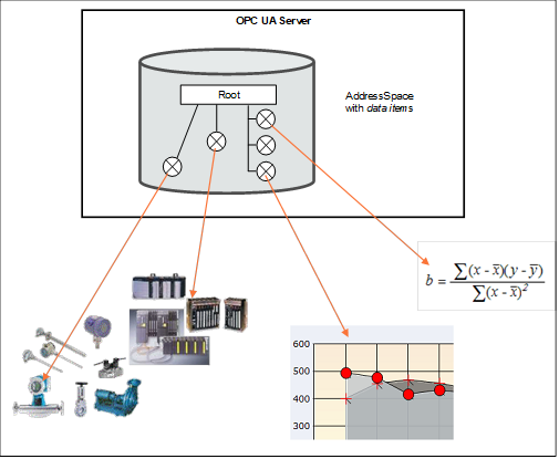
Data Access deals with the representation and use of automation data in Servers.
Automation data can be located inside the Server or on I/O cards directly connected to the Server. It can also be located in sub-servers or on other devices such as controllers and input/output modules, connected by serial links via field buses or other communication links. OPC UA Data Access Servers provide one or more OPC UA Data Access Clients with transparent access to their automation data.
The links to automation data instances are called DataItems. Which categories of automation data are provided is completely vendor-specific. Figure 1 illustrates how the AddressSpace of a Server can contain a broad range of different DataItems.
Figure 1 – OPC DataItems are linked to automation data
Clients can read or write DataItems, or monitor them for value changes. The Services needed for these operations are specified in OPC 10000-4. Changes are defined as a change in status (quality) or a change in value that exceeds a client-defined range called a Deadband. To detect the value change, the difference between the current value and the last reported value is compared to the Deadband.
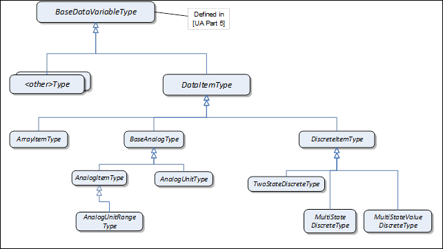
The DataAccess model extends the variable model by defining VariableTypes. The DataItemType is the base type. ArrayItemType, BaseAnalogType and DiscreteItemType are specializations. See Figure 2. Each of these VariableTypes can be further extended to form domain or server specific DataItems.
Figure 2 – DataItem VariableType hierarchy
The StatusCode also contains an informational bit called SemanticsChanged.
Servers that implement Data Access shall set this Bit in notifications if certain Property values defined in this standard change. The corresponding Properties are specified individually for each VariableType.
Clients that use any of these Properties should re-read them before they process the data value.
This VariableType defines the general characteristics of a DataItem. All other DataItem Types derive from it. The DataItemType derives from the BaseDataVariableType and therefore shares the variable model as described in OPC 10000-3 and OPC 10000-5. It is formally defined in Table 1.
Table 1 – DataItemType definition
|
Attribute |
Value |
||||
|
BrowseName |
DataItemType |
||||
|
IsAbstract |
False |
||||
|
ValueRank |
−2 (−2 = ‘Any’) |
||||
|
DataType |
BaseDataType |
||||
|
References |
NodeClass |
BrowseName |
DataType |
TypeDefinition |
ModellingRule |
|
Subtype of the BaseDataVariableType defined in OPC 10000-5; i.e the Properties of that type are inherited. |
|||||
|
HasSubtype |
VariableType |
BaseAnalogType |
Defined in 5.3.2.2 |
||
|
HasSubtype |
VariableType |
DiscreteItemType |
Defined in 5.3.3 |
||
|
HasSubtype |
VariableType |
ArrayItemType |
Defined in 5.3.4 |
||
|
HasProperty |
Variable |
Definition |
String |
PropertyType |
Optional |
|
HasProperty |
Variable |
ValuePrecision |
Double |
PropertyType |
Optional |
|
Conformance Units |
|||||
|
Data Access DataItems |
|||||
Definition is a vendor-specific, human readable string that specifies how the value of this DataItem is calculated. Definition is non-localized and will often contain an equation that can be parsed by certain clients.
Example: Definition::= “(TempA – 25) + TempB”
ValuePrecision specifies the maximum precision that the Server can maintain for the item based on restrictions in the target environment.
ValuePrecision can be used for the following DataTypes:
· For Float, Double, and Decimal values it specifies the number of digits after the decimal place when it is a positive number. When it is a negative number, it specifies the number of insignificant digits to the left of the decimal place.
For example a ValuePrecision of -2 specifies that the precision of the Value is to the nearest 100. The ValuePrecision should always be a whole number and it shall always be interpreted as a whole number by rounding it to the nearest whole number.
· For DateTime values it shall always be a positive number which indicates the minimum time difference in nanoseconds. For example, a ValuePrecision of 20 000 000 defines a precision of 20 ms. The ValuePrecision should always be a whole number and it shall always be interpreted as a whole number by rounding it to the nearest whole number.
· ValuePrecision can also be used for other subtypes of Double (like Duration) and other Number subtypes that can be represented by a Double.
The ValuePrecision Property is an approximation that is intended to provide guidance to a Client. A Server is expected to silently round any value with more precision that it supports. This implies that a Client can encounter cases where the value read back from a Server differs from the value that it wrote to the Server. This difference shall be no more than the difference suggested by this Property.
The algorithm for rounding should follow the so-called “Banker’s rounding” (aka Round half to even), in which numbers which are equidistant from the two nearest integers are rounded to the nearest even integer. Thus, 0.5 rounds down to 0; 1.5 rounds up to 2.
Other decimal fractions round as you would expect: 0.4 to 0, 0.6 to 1, 1.4 to 1, 1.6 to 2, etc. Only x.5 numbers get the "special" treatment.
The VariableTypes in this subclause define the characteristics of AnalogItems. The types have identical semantics and Properties but with diverging ModellingRules for individual Properties.
The Properties are only described once - in 5.3.2.2. The descriptions apply to the Properties for the other VariableTypes as well.
This VariableType is the base type for analog items. All Properties are optional. Subtypes of this base type will mandate some of the Properties. The BaseAnalogType derives from the DataItemType. It is formally defined in Table 2.
Table 2 – BaseAnalogType definition
|
Attribute |
Value |
||||
|
BrowseName |
BaseAnalogType |
||||
|
IsAbstract |
False |
||||
|
ValueRank |
−2 (−2 = ‘Any’) |
||||
|
DataType |
Number |
||||
|
References |
NodeClass |
BrowseName |
DataType |
TypeDefinition |
ModellingRule |
|
Subtype of the DataItemType defined in 5.3.1; i.e. the Properties of that type are inherited. |
|||||
|
HasSubtype |
VariableType |
AnalogItemType |
Defined in 5.3.2.3 |
||
|
HasSubtype |
VariableType |
AnalogUnitType |
Defined in 5.3.2.4 |
||
|
HasProperty |
Variable |
InstrumentRange |
Range |
PropertyType |
Optional |
|
HasProperty |
Variable |
EURange |
Range |
PropertyType |
Optional |
|
HasProperty |
Variable |
EngineeringUnits |
EUInformation |
PropertyType |
Optional |
|
Conformance Units |
|||||
|
Data Access BaseAnalogType |
|||||
The following paragraphs describe the Properties of this VariableType. If the analog item’s Value contains an array, the Properties shall apply to all elements in the array.
InstrumentRange defines the value range that can be returned by the instrument.
Example: InstrumentRange::= {-9999.9, 9999.9}
Although defined as optional, it is strongly recommended for Servers to support this Property. Without an InstrumentRange being provided, Clients will commonly assume the full range according to the DataType.
The InstrumentRange Property can also be used to restrict a Built-in DataType such as Byte or Int16) to a smaller range of values.
Examples:
UInt4: InstrumentRange::= {0, 15}
Int6: InstrumentRange::= {-32, 31}
The Range DataType is specified in 5.6.2.
EURange defines the value range likely to be obtained in normal operation. It is intended for such use as automatically scaling a bar graph display.
Sensor or instrument failure or deactivation can result in a returned item value which is actually outside of this range. Client software must be prepared to deal with this possibility. Similarly a Client can attempt to write a value that is outside of this range back to the server. The exact behaviour (accept, reject, clamp, etc.) in this case is Server-dependent. However, in general Servers shall be prepared to handle this.
Example: EURange::= {-200.0,1400.0}
See also 7.2 for a special monitoring filter (PercentDeadband) which is based on the engineering unit range.
NOTE If EURange is not provided on an instance, the PercentDeadband filter cannot be used for that instance (see clause 7.2).
EngineeringUnits specifies the units for the DataItem’s value (e.g., DEGC, hertz, seconds). The EUInformation type is specified in 5.6.3. The NonHierarchical References HasQuantity (see 6.5.2) and HasEngineeringUnitDetail (see 6.5.1) can be used to expose further information for the unit.
It is important to note that understanding the units of a measurement value is essential for a uniform system. In an open system in particular where Servers from different cultures can be used, it is essential to know what the units of measurement are. Based on such knowledge, values can be converted if necessary before being used. Therefore, although defined as optional, support of the EngineeringUnits Property is strongly advised.
OPC UA recommends using the “Codes for Units of Measurement” (see UN/CEFACT: UNECE Recommendation N° 20). The mapping to the EngineeringUnits Property is specified in 5.6.3.
Examples for unit mixup: In 1999, the Mars Climate Orbiter crashed into the surface of Mars. The main reason was a discrepancy over the units used. The navigation software expected data in newton second; the company who built the orbiter provided data in pound-force seconds. Another, less expensive, disappointment occurs when people used to British pints order a pint in the USA, only to be served what they consider a short measure.
The StatusCode SemanticsChanged bit shall be set if any of the EURange (could change the behaviour of a Subscription if a PercentDeadband filter is used) or EngineeringUnits (could create problems if the Client uses the value to perform calculations) Properties are changed (see clause 5.2 for additional information).
This VariableType requires the EURange Property. The AnalogItemType derives from the BaseAnalogType. It is formally defined in Table 3.
Table 3 – AnalogItemType definition
|
Attribute |
Value |
||||
|
BrowseName |
AnalogItemType |
||||
|
IsAbstract |
False |
||||
|
ValueRank |
−2 (−2 = ‘Any’) |
||||
|
DataType |
Number |
||||
|
References |
NodeClass |
BrowseName |
DataType |
TypeDefinition |
ModellingRule |
|
Subtype of the BaseAnalogType defined in 5.3.2.2; i.e. the Properties of that type are inherited. |
|||||
|
HasSubtype |
VariableType |
AnalogUnitRangeType |
Defined in 5.3.2.5 |
||
|
HasProperty |
Variable |
EURange |
Range |
PropertyType |
Mandatory |
|
Conformance Units |
|||||
|
Data Access AnalogItemType |
|||||
This VariableType requires the EngineeringUnits Property. The AnalogUnitType derives from the BaseAnalogType. It is formally defined in Table 4.
Table 4 – AnalogUnitType definition
|
Attribute |
Value |
||||
|
BrowseName |
AnalogUnitType |
||||
|
IsAbstract |
False |
||||
|
ValueRank |
−2 (−2 = ‘Any’) |
||||
|
DataType |
Number |
||||
|
References |
NodeClass |
BrowseName |
DataType |
TypeDefinition |
ModellingRule |
|
Subtype of the BaseAnalogType defined in 5.3.2.2; i.e. the Properties of that type are inherited. |
|||||
|
HasProperty |
Variable |
EngineeringUnits |
EUInformation |
PropertyType |
Mandatory |
|
Conformance Units |
|||||
|
Data Access AnalogUnitType |
|||||
The AnalogUnitRangeType derives from the AnalogItemType and additionally requires the EngineeringUnits Property. It is formally defined in Table 5.
Table 5 – AnalogUnitRangeType definition
|
Attribute |
Value |
||||
|
BrowseName |
AnalogUnitRangeType |
||||
|
IsAbstract |
False |
||||
|
ValueRank |
−2 (−2 = ‘Any’) |
||||
|
DataType |
Number |
||||
|
References |
NodeClass |
BrowseName |
DataType |
TypeDefinition |
ModellingRule |
|
Subtype of the AnalogItemType defined in 5.3.2.3; i.e. the Properties of that type are inherited. |
|||||
|
HasProperty |
Variable |
EngineeringUnits |
EUInformation |
PropertyType |
Mandatory |
|
Conformance Units |
|||||
|
Data Access AnalogUnitRangeType |
|||||
This VariableType is an abstract type. That is, no instances of this type can exist. However, it can be used in a filter when browsing or querying. The DiscreteItemType derives from the DataItemType and therefore shares all of its characteristics. It is formally defined in Table 6.
Table 6 – DiscreteItemType definition
|
Attribute |
Value |
||||
|
BrowseName |
DiscreteItemType |
||||
|
IsAbstract |
True |
||||
|
ValueRank |
−2 (−2 = ‘Any’) |
||||
|
DataType |
BaseDataType |
||||
|
References |
NodeClass |
BrowseName |
DataType |
TypeDefinition |
ModellingRule |
|
Subtype of the DataItemType defined in 5.2; i.e. the Properties of that type are inherited. |
|||||
|
HasSubtype |
VariableType |
TwoStateDiscreteType |
Defined in 5.3.3.2 |
||
|
HasSubtype |
VariableType |
MultiStateDiscreteType |
Defined in 5.3.3.3 |
||
|
HasSubtype |
VariableType |
MultiStateValueDiscreteType |
Defined in 5.3.3.4 |
||
|
Conformance Units |
|||||
|
Data Access DiscreteItemType |
|||||
This VariableType defines the general characteristics of a DiscreteItem that can have two states. The TwoStateDiscreteType derives from the DiscreteItemType. It is formally defined in Table 7.
Table 7 – TwoStateDiscreteType definition
|
Attribute |
Value |
|
||||
|
BrowseName |
TwoStateDiscreteType |
|
||||
|
IsAbstract |
False |
|
||||
|
ValueRank |
−2 (−2 = ‘Any’) |
|
||||
|
DataType |
Boolean |
|
||||
|
References |
NodeClass |
BrowseName |
DataType |
TypeDefinition |
ModellingRule |
|
|
Subtype of the DiscreteItemType defined in 5.3.3; i.e. the Properties of that type are inherited. |
|
|||||
|
HasProperty |
Variable |
TrueState |
LocalizedText |
PropertyType |
Mandatory |
|
|
HasProperty |
Variable |
FalseState |
LocalizedText |
PropertyType |
Mandatory |
|
|
Conformance Units |
||||||
|
Data Access TwoState |
||||||
TrueState contains a string to be associated with this DataItem when it is TRUE. This is typically used for a contact when it is in the closed (non-zero) state.
for example: "RUN", "CLOSE", "ENABLE", "SAFE", etc.
FalseState contains a string to be associated with this DataItem when it is FALSE. This is typically used for a contact when it is in the open (zero) state.
for example: "STOP", "OPEN", "DISABLE", "UNSAFE", etc.
If the item contains an array, then the Properties will apply to all elements in the array.
The StatusCode SemanticsChanged bit shall be set if any of the FalseState or TrueState Properties are changed (see 5.2 for additional information).
This VariableType defines the general characteristics of a DiscreteItem that can have more than two states. The MultiStateDiscreteType derives from the DiscreteItemType. It is formally defined in Table 8.
Table 8 – MultiStateDiscreteType definition
|
Attribute |
Value |
||||
|
BrowseName |
MultiStateDiscreteType |
||||
|
IsAbstract |
False |
||||
|
ValueRank |
−2 (−2 = ‘Any’) |
||||
|
DataType |
UInteger |
||||
|
References |
NodeClass |
BrowseName |
DataType |
TypeDefinition |
ModellingRule |
|
Subtype of the DiscreteItemType defined in 5.3.3; i.e. the Properties of that type are inherited. |
|||||
|
HasProperty |
Variable |
EnumStrings |
LocalizedText[] |
PropertyType |
Mandatory |
|
Conformance Units |
|||||
|
Data Access MultiState |
|||||
EnumStrings is a string lookup table corresponding to sequential numeric values (0, 1, 2, etc.)
Example:
"OPEN"
"CLOSE"
"IN TRANSIT" etc.
Here the string "OPEN" corresponds to 0, "CLOSE" to 1 and "IN TRANSIT" to 2.
Clients should be prepared to handle item values outside of the range of the list; and robust servers should be prepared to handle writes of illegal values, by providing errorcode “Bad_OutOfRange”.
If the item contains an array then this lookup table shall apply to all elements in the array.
NOTE The EnumStrings property is also used for Enumeration DataTypes (for the specification of this DataType, see OPC 10000-3).
The StatusCode SemanticsChanged bit shall be set if the EnumStrings Property is changed (see 5.2 for additional information).
This VariableType defines the general characteristics of a DiscreteItem that can have more than two states and where the state values (the enumeration) do not consist of consecutive numeric values (can have gaps) or where the enumeration is not zero-based. The MultiStateValueDiscreteType derives from the DiscreteItemType. It is formally defined in Table 9.
Table 9 – MultiStateValueDiscreteType definition
|
Attribute |
Value |
|||
|
BrowseName |
MultiStateValueDiscreteType |
|||
|
IsAbstract |
False |
|||
|
ValueRank |
−2 (−2 = ‘Any’) |
|||
|
DataType |
Number |
|||
|
References |
NodeClass |
BrowseName |
DataType TypeDefinition |
ModellingRule |
|
Subtype of the DiscreteItemType defined in 5.3.3; i.e. the Properties of that type are inherited. |
||||
|
HasProperty |
Variable |
EnumValues |
EnumValueType[] |
Mandatory |
|
HasProperty |
Variable |
ValueAsText |
LocalizedText |
Mandatory |
|
Conformance Units |
||||
|
Data Access MultiStateValueDiscrete |
||||
EnumValues is an array of EnumValueType. Each entry of the array represents one enumeration value with its integer notation, a human-readable representation, and help information. This represents enumerations with integers that are not zero-based or have gaps (e.g. 1, 2, 4, 8, 16). See OPC 10000-3 for the definition of this type. MultiStateValueDiscrete Variables expose the current integer notation in their Value Attribute. Clients will often read the EnumValues Property in advance and cache it to lookup a name or help whenever they receive the numeric representation.
Only DataTypes that can be represented with EnumValues are allowed for Variables of MultiStateValueDiscreteType. These are Integers up to 64 Bits (signed and unsigned).
The numeric representation of the current enumeration value is provided via the Value Attribute of the MultiStateValueDiscrete Variable. If the Value is scalar, the ValueAsText Property provides the localized text representation of the enumeration value. It can be used by Clients only interested in displaying the text to subscribe to the Property instead of the Value Attribute. If the Value is not scalar then ValueAsText should be Null. In that case, Clients can use the EnumValues Property to lookup the display information.
The StatusCode SemanticsChanged bit shall be set if the EnumValues Property value is changed (see clause 5.2 for additional information).
This abstract VariableType defines the general characteristics of an ArrayItem. Values are exposed in an array but the content of the array represents a single entity like an image. Other DataItems can contain arrays that represent for example several values of several temperature sensors of a boiler.
ArrayItemType or its subtype shall only be used when the Title and AxisScaleType Properties can be filled with reasonable values. If this is not the case DataItemType and subtypes like AnalogItemType, which also support arrays, shall be used. The ArrayItemType is formally defined in Table 10.
Table 10 – ArrayItemType definition
|
Attribute |
Value |
||||
|
BrowseName |
ArrayItemType |
||||
|
IsAbstract |
True |
||||
|
ValueRank |
0 (0 = OneOrMoreDimensions) |
||||
|
DataType |
BaseDataType |
||||
|
References |
NodeClass |
BrowseName |
DataType |
TypeDefinition |
ModellingRule |
|
Subtype of the DataItemType defined in 5.3.1; i.e. the Properties of that type are inherited. |
|||||
|
HasSubtype |
VariableType |
YArrayItemType |
Defined in 5.3.4.2 |
||
|
HasSubtype |
VariableType |
XYArrayItemType |
Defined in 5.3.4.3 |
||
|
HasSubtype |
VariableType |
ImageItemType |
Defined in 5.3.4.4 |
||
|
HasSubtype |
VariableType |
CubeItemType |
Defined in 5.3.4.5 |
||
|
HasSubtype |
VariableType |
NDimensionArrayItemType |
Defined in 5.3.4.6 |
||
|
HasProperty |
Variable |
InstrumentRange |
Range |
PropertyType |
Optional |
|
HasProperty |
Variable |
EURange |
Range |
PropertyType |
Mandatory |
|
HasProperty |
Variable |
EngineeringUnits |
EUInformation |
PropertyType |
Mandatory |
|
HasProperty |
Variable |
Title |
LocalizedText |
PropertyType |
Mandatory |
|
HasProperty |
Variable |
AxisScaleType |
AxisScaleEnumeration |
PropertyType |
Mandatory |
|
Conformance Units |
|||||
|
Data Access ArrayItem2Type |
|||||
InstrumentRange defines the range of the Value of the ArrayItem.
EURange defines the value range of the ArrayItem likely to be obtained in normal operation. It is intended for such use as automatically scaling a bar graph display.
EngineeringUnits holds the information about the engineering units of the Value of the ArrayItem.
For additional information about InstrumentRange, EURange, and EngineeringUnits see the description of BaseAnalogType in 5.3.2.2.
Title holds the user readable title of the Value of the ArrayItem.
AxisScaleType defines the scale to be used for the axis where the Value of the ArrayItem shall be displayed.
The StatusCode SemanticsChanged bit shall be set if any of the InstrumentRange, EURange, EngineeringUnits or Title Properties are changed (see 5.2 for additional information).
YArrayItemType represents a single-dimensional array of numerical values used to represent spectra or distributions where the x axis intervals are constant. YArrayItemType is formally defined in Table 11.
Table 11 – YArrayItemType definition
|
Attribute |
Value |
||||
|
BrowseName |
YArrayItemType |
||||
|
IsAbstract |
False |
||||
|
ValueRank |
1 |
||||
|
DataType |
BaseDataType |
||||
|
ArrayDimensions |
{0} (0 = UnknownSize) |
||||
|
References |
NodeClass |
BrowseName |
DataType |
TypeDefinition |
ModellingRule |
|
Subtype of the ArrayItemType defined in 5.3.4.1 |
|||||
|
|
|
|
|
|
|
|
HasProperty |
Variable |
XAxisDefinition |
AxisInformation |
PropertyType |
Mandatory |
|
Conformance Units |
|||||
|
Data Access YArrayItemType |
|||||
The Value of the YArrayItem contains the numerical values for the Y-Axis. Engineering Units and Range for the Value are defined by corresponding Properties inherited from the ArrayItemType.
The DataType of this VariableType is restricted to SByte, Int16, Int32, Int64, Float, Double, ComplexNumberType and DoubleComplexNumberType.
The XAxisDefinition Property holds the information about the Engineering Units and Range for the X-Axis.
The StatusCode SemanticsChanged bit shall be set if any of the following five Properties are changed: InstrumentRange, EURange, EngineeringUnits, Title or XAxisDefinition (see 5.2 for additional information).
Figure 3 shows an example of how Attributes and Properties can be used in a graphical interface.
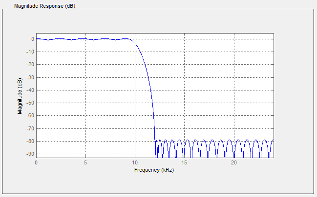
Figure 3 – Graphical view of a YArrayItem
Table 12 describes the values of each element presented in Figure 3.
Table 12 – YArrayItem item description
|
Attribute / Property |
Item value |
|
Description |
Magnitude Response (dB) |
|
axisScaleType |
AxisScaleEnumeration.LINEAR |
|
InstrumentRange.low |
-90 |
|
InstrumentRange.high |
5 |
|
EURange.low |
-90 |
|
EURange.high |
2 |
|
EngineeringUnits.namespaceUrl |
http://www.opcfoundation.org/UA/units/un/cefact |
|
EngineeringUnits.unitId |
12878 |
|
EngineeringUnits.displayName |
“en-us”, “dB” |
|
EngineeringUnits.description |
“en-us”, “decibel” |
|
Title |
Magnitude |
|
XAxisDefinition.EngineeringUnits.namespaceUrl |
http://www.opcfoundation.org/UA/units/un/cefact |
|
XAxisDefinition.EngineeringUnits.unitId |
4933722 |
|
XAxisDefinition.EngineeringUnits.displayName |
“en-us”, “kHz” |
|
XAxisDefinition.EngineeringUnits.description |
“en-us”, “kilohertz” |
|
XAxisDefinition.Range.low |
0 |
|
XAxisDefinition.Range.high |
25 |
|
XAxisDefinition.title |
“en-us”, “Frequency” |
|
XAxisDefinition.axisScaleType |
AxisScaleEnumeration.LINEAR |
|
XAxisDefinition.axisSteps |
null |
Interpretation notes:
· Not all elements of this table are used in the graphic.
· The X axis is displayed in reverse order, however, the XAxisDefinition.Range.low shall be lower than XAxisDefinition.Range.high. It is only a graphical representation that reverses the display order.
· There is a constant X axis
XYArrayItemType represents a vector of XVType values like a list of peaks, where XVType.x is the position of the peak and XVType.value is its intensity. XYArrayItemType is formally defined in Table 13.
Table 13 – XYArrayItemType definition
|
Attribute |
Value |
||||
|
BrowseName |
XYArrayItemType |
||||
|
IsAbstract |
False |
||||
|
ValueRank |
1 |
||||
|
DataType |
XVType |
||||
|
References |
NodeClass |
BrowseName |
DataType |
TypeDefinition |
ModellingRule |
|
Subtype of the ArrayItemType defined in 5.3.4.1 |
|||||
|
|
|
|
|
|
|
|
HasProperty |
Variable |
XAxisDefinition |
AxisInformation |
PropertyType |
Mandatory |
|
Conformance Units |
|||||
|
Data Access XYArrayItemType |
|||||
The Value of the XYArrayItem contains an array of structures (XVType) where each structure specifies the position for the X-Axis (XVType.x) and the value itself (XVType.value), used for the Y-Axis. Engineering units and range for the Value are defined by corresponding Properties inherited from the ArrayItemType.
XAxisDefinition Property holds the information about the Engineering Units and Range for the X-Axis.
The axisSteps of XAxisDefinition shall be set to NULL because it is not used.
The StatusCode SemanticsChanged bit shall be set if any of the InstrumentRange, EURange, EngineeringUnits, Title or XAxisDefinition Properties are changed (see 5.2 for additional information).
ImageItemType defines the general characteristics of an ImageItem which represents a matrix of values like an image, where the pixel position is given by X which is the column and Y the row. The value is the pixel intensity.
ImageItemType is formally defined in Table 14.
Table 14 – ImageItemType definition
|
Attribute |
Value |
||||
|
BrowseName |
ImageItemType |
||||
|
IsAbstract |
False |
||||
|
ValueRank |
2 (2 = two dimensional array) |
||||
|
DataType |
BaseDataType |
||||
|
References |
NodeClass |
BrowseName |
DataType |
TypeDefinition |
ModellingRule |
|
Subtype of the ArrayItemType defined in 5.3.4.1 |
|||||
|
|
|
|
|
|
|
|
HasProperty |
Variable |
XAxisDefinition |
AxisInformation |
PropertyType |
Mandatory |
|
HasProperty |
Variable |
YAxisDefinition |
AxisInformation |
PropertyType |
Mandatory |
|
Conformance Units |
|||||
|
Data Access ImageItemType |
|||||
Engineering units and range for the Value are defined by corresponding Properties inherited from the ArrayItemType.
The DataType of this VariableType is restricted to SByte, Int16, Int32, Int64, Float, Double, ComplexNumberType and DoubleComplexNumberType.
The ArrayDimensions Attribute for Variables of this type or subtypes shall use the first entry in the array ([0]) to define the number of columns and the second entry ([1]) to define the number of rows, assuming the size of the matrix is not dynamic.
XAxisDefinition Property holds the information about the engineering units and range for the X-Axis.
YAxisDefinition Property holds the information about the engineering units and range for the Y-Axis.
The StatusCode.SemanticsChanged bit shall be set if any of the InstrumentRange, EURange, EngineeringUnits, Title, XAxisDefinition or YAxisDefinition Properties are changed.
CubeItemType represents a cube of values like a spatial particle distribution, where the particle position is given by X which is the column, Y the row and Z the depth. In the example of a spatial partical distribution, the value is the particle size. CubeItemType is formally defined in Table 15.
Table 15 – CubeItemType definition
|
Attribute |
Value |
|
||||
|
BrowseName |
CubeItemType |
|
||||
|
IsAbstract |
False |
|
||||
|
ValueRank |
3 (3 = three dimensional array) |
|
||||
|
DataType |
BaseDataType |
|
||||
|
References |
NodeClass |
BrowseName |
DataType |
TypeDefinition |
ModellingRule |
|
|
Subtype of the ArrayItemType defined in 5.3.4.1 |
|
|||||
|
|
|
|
|
|
|
|
|
HasProperty |
Variable |
XAxisDefinition |
AxisInformation |
PropertyType |
Mandatory |
|
|
HasProperty |
Variable |
YAxisDefinition |
AxisInformation |
PropertyType |
Mandatory |
|
|
HasProperty |
Variable |
ZAxisDefinition |
AxisInformation |
PropertyType |
Mandatory |
|
|
Conformance Units |
||||||
|
Data Access CubeItemType |
||||||
Engineering units and range for the Value are defined by corresponding Properties inherited from the ArrayItemType.
The DataType of this VariableType is restricted to SByte, Int16, Int32, Int64, Float, Double, ComplexNumberType and DoubleComplexNumberType.
The ArrayDimensions Attribute for Variables of this type or subtypes should use the first entry in the array ([0]) to define the number of columns, the second entry ([1]) to define the number of rows, and the third entry ([2]) define the number of steps in the Z axis, assuming the size of the matrix is not dynamic.
XAxisDefinition Property holds the information about the engineering units and range for the X-Axis.
YAxisDefinition Property holds the information about the engineering units and range for the Y-Axis.
ZAxisDefinition Property holds the information about the engineering units and range for the Z-Axis.
The StatusCode SemanticsChanged bit shall be set if any of the InstrumentRange, EURange, EngineeringUnits, Title, XAxisDefinition, YAxisDefinition or ZAxisDefinition Properties are changed (see 5.2 for additional information).
This VariableType defines a generic multi-dimensional ArrayItem.
This approach minimizes the number of types however it can be proved more difficult to utilize for control system interactions.
NDimensionArrayItemType is formally defined in Table 16.
Table 16 – NDimensionArrayItemType definition
|
Attribute |
Value |
||||
|
BrowseName |
NDimensionArrayItemType |
||||
|
IsAbstract |
False |
||||
|
ValueRank |
0 (0 = OneOrMoreDimensions) |
||||
|
DataType |
BaseDataType |
||||
|
References |
NodeClass |
BrowseName |
DataType |
TypeDefinition |
ModellingRule |
|
Subtype of the ArrayItemType defined in 5.3.4.1 |
|||||
|
|
|
|
|
|
|
|
HasProperty |
Variable |
AxisDefinition |
AxisInformation [] |
PropertyType |
Mandatory |
|
Conformance Units |
|||||
|
Data Access NDimensionArrayItemType |
|||||
The DataType of this VariableType is restricted to SByte, Int16, Int32, Int64, Float, Double, ComplexNumberType and DoubleComplexNumberType.
AxisDefinition Property holds the information about the EngineeringUnits and Range for all axis.
The StatusCode SemanticsChanged bit shall be set if any of the InstrumentRange, EURange, EngineeringUnits, Title or AxisDefinition Properties are changed (see 5.2 for additional information).
DataItems are always defined as data components of other Nodes in the AddressSpace. They are never defined by themselves. A simple example of a container for DataItems would be a “Folder Object” but it can be an Object of any other type.
Figure 4 illustrates the basic AddressSpace model of a DataItem, in this case an AnalogItem.
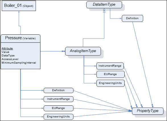
Figure 4 – Representation of DataItems in the AddressSpace
Each DataItem is represented by a DataVariable with a specific set of Attributes. The TypeDefinition reference indicates the type of the DataItem (in this case the AnalogItemType). Additional characteristics of DataItems are defined using Properties. The VariableTypes in 5.2 specify which properties can exist. These Properties have been found to be useful for a wide range of Data Access clients. Servers that want to disclose similar information should use the OPC-defined Property rather than one that is vendor-specific.
The above figure shows only a subset of Attributes and Properties. Other Attributes that are defined for Variables in OPC 10000-3 (e.g., Description) can also be available.
This subclause lists the Attributes of Variables that have particular importance for Data Access. They are specified in detail in OPC 10000-3. The following Attributes are particularly important for Data Access:
· Value
· DataType
· AccessLevel
· MinimumSamplingInterval
Value is the most recent value of the Variable that the Server has. Its data type is defined by the DataType Attribute. The AccessLevel Attribute defines the Server’s basic ability to access current data and MinimumSamplingInterval defines how current the data is.
When a client requests the Value Attribute for reading or monitoring, the Server will always return a StatusCode (the quality and the Server’s ability to access/provide the value) and, optionally, a ServerTimestamp and/or a SourceTimestamp – based on the Client’s request. See OPC 10000-4 for details on StatusCode and the meaning of the two timestamps. Specific status codes for Data Access are defined in 7.3.
Following is a description of the DataTypes defined in this specification.
DataTypes like String, Boolean, Double or LocalizedText are defined in OPC 10000-3. Their representation is specified in OPC 10000-5.
This structure defines the Range for a value. Its elements are defined in Table 17.
Table 17 – Range DataType structure
|
Name |
Type |
Description |
|
Range |
structure |
|
|
low |
Double |
Lowest value in the range. |
|
high |
Double |
Highest value in the range. |
NOTE For some DataTypes, e.g. Int64, UInt64, or Decimal, there can be a loss in precision in the representation of the range with a Double.
If a limit is not known a NaN shall be used.
Its representation in the AddressSpace is defined in Table 18
Table 18 – Range definition
|
Attribute |
Value |
|||||
|
BrowseName |
Range |
|||||
|
IsAbstract |
False |
|||||
|
References |
NodeClass |
BrowseName |
DataType |
TypeDefinition |
Other |
|
|
Subtype of Structure defined in OPC 10000-5. |
||||||
|
Conformance Units |
||||||
|
Base Info Range DataType |
||||||
EUInformation contains information about the EngineeringUnits.
The intention of the OPC UA standard is not to define a set of units but a way to expose units based on existing systems. Since there is not a single worldwide set of units used in all industries, the EUInformation structure includes a separate field (the namespaceUri) to identify the system on which the exposed unit is based.
The default OPC UA mapping is based on UN/CEFACT as defined in 5.6.3.4, because it can be programmatically interpreted by generic OPC UA Clients. However, the EUInformation structure has been defined such that other standards bodies can incorporate their engineering unit definitions into OPC UA. If Servers use such an approach, then they shall identify this standards body by using a proper URI in EUInformation.namespaceUri.
Servers can enhance EUInformation by providing the Quantity and Unit model (see 6) and referencing from EUInformation instances to the appropriate instances for quantity and unit. See Figure 5 for an example.
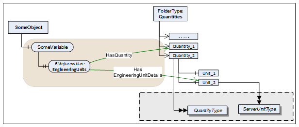
Figure 5 – Enhanced EUInformation example
The EUInformation elements are defined in Table 19.
Table 19 – EUInformation DataType structure
|
Name |
Type |
Description |
|
EUInformation |
structure |
|
|
namespaceUri |
String |
Identifies the organization (company, standards organization) that defines the EUInformation. |
|
unitId |
Int32 |
Identifier for programmatic lookup. −1 is used if a unitId is not available. |
|
displayName |
LocalizedText |
The displayName of the engineering unit is typically the abbreviation of the engineering unit, for example "h" for hour or "m/s" for meter per second. |
|
description |
LocalizedText |
Contains the full name of the engineering unit such as "hour" or "meter per second". |
Its representation in the AddressSpace is defined in Table 20.
Table 20 – EUInformation definition
|
Attribute |
Value |
|||||
|
BrowseName |
EUInformation |
|||||
|
IsAbstract |
False |
|||||
|
References |
NodeClass |
BrowseName |
DataType |
TypeDefinition |
Other |
|
|
Subtype of Structure defined in OPC 10000-5. |
||||||
|
Conformance Units |
||||||
|
Base Info EUInformation |
||||||
This clause specifies how to apply the “Codes for Units of Measurement” published by the “United Nations Centre for Trade Facilitation and Electronic Business” (see UNECE). This recommendation establishes a single list of code elements to represent units of the International System of Units (SI Units) like units of measure for length, mass (weight), volume and other quantities and in addition covers administration, commerce, transport, science, technology, industry etc. It provides a fixed code that can be used for automated evaluation.
Table 21 contains a small excerpt of the relevant columns in the UNECE recommendation:
Table 21 – Examples from the UNECE Recommendation
|
Excerpt from Recommendation N°. 20, Annex 1 |
||
|
Common Code |
Name |
Symbol |
|
C81 |
radian |
rad |
|
C25 |
milliradian |
mrad |
|
MMT |
millimetre |
mm |
|
HMT |
hectometre |
hm |
|
KMT |
kilometre |
km |
|
KMQ |
kilogram per cubic metre |
kg/m3 |
|
FAH |
degree Fahrenheit |
°F |
The UNECE recommendation in several cases defines multiple instances of the same unit (same name and symbol) for different quantities. Therefore, the relevant information for EUInformation.unitId, EUInformation.displayName, and EUInformation.description has been extracted by eliminating duplicates. This extract is available here:
http://www.opcfoundation.org/UA/EngineeringUnits/UNECE/UNECE_to_OPCUA.csv
This mapping has been generated as follows:
· The namespaceUri shall be http://www.opcfoundation.org/UA/units/un/cefact
· The Common Code (represented as an alphanumeric variable length of up to 3 characters) has been converted into a 32 Bit Integer and is used for the unitId. The following pseudo code specifies the conversion algorithm:
Int32
unitId = 0;
Int32 c;
for (i=0; i<=3;i++)
{
c = CommonCode[i];
if (c == 0) break; // end of Common Code
unitId = unitId << 8;
unitId = unitId | c;
}
· The Symbol field shall be used as invariant locale for displayName. Servers can configure multiple additional locales for each displayName. However, if none of the LocaleIds specified by the Client for the Session matches these additional locales, the Server shall return the invariant locale.
· The Name field shall be used as invariant locale for description. Servers can configure multiple additional locales for each description. However, if none of the LocaleIds specified by the Client for the Session matches these additional locales, the Server shall return the invariant locale.
This structure defines float IEEE 32 bits complex value. Its elements are defined in Table 22.
Table 22 – ComplexNumberType DataType structure
|
Name |
Type |
Description |
|
ComplexNumberType |
structure |
|
|
real |
Float |
Value real part |
|
imaginary |
Float |
Value imaginary part |
Its representation in the AddressSpace is defined in Table 23
Table 23 – ComplexNumberType definition
|
Attribute |
Value |
|||||
|
BrowseName |
ComplexNumberType |
|||||
|
IsAbstract |
False |
|||||
|
References |
NodeClass |
BrowseName |
DataType |
TypeDefinition |
Other |
|
|
Subtype of Structure defined in OPC 10000-5. |
||||||
|
Conformance Units |
||||||
|
Data Access Complex Number |
||||||
This structure defines double IEEE 64 bits complex value. Its elements are defined in Table 24.
Table 24 – DoubleComplexNumberType DataType structure
|
Name |
Type |
Description |
|
DoubleComplexNumberType |
structure |
|
|
real |
Double |
Value real part |
|
imaginary |
Double |
Value imaginary part |
Its representation in the AddressSpace is defined in Table 25.
Table 25 – DoubleComplexNumberType definition
|
Attribute |
Value |
|||||
|
BrowseName |
DoubleComplexNumberType |
|||||
|
IsAbstract |
False |
|||||
|
References |
NodeClass |
BrowseName |
DataType |
TypeDefinition |
Other |
|
|
Subtype of Structure defined in OPC 10000-5. |
||||||
|
Conformance Units |
||||||
|
Data Access DoubleComplex Number |
||||||
This structure defines the information for auxiliary axis for ArrayItemType Variables.
There are three typical uses of this structure:
a) The step between points is constant and can be predicted using the range information and the number of points. In this case, axisSteps can be set to NULL.
b) The step between points is not constant, but remains the same for a long period of time (from acquisition to acquisition for example). In this case, axisSteps contains the value of each step on the axis.
c) The step between points is not constant and changes at every update. In this case, a type like XYArrayType shall be used and axisSteps is set to NULL.
Its elements are defined in Table 26.
Table 26 – AxisInformation DataType structure
|
Name |
Type |
Description |
|
AxisInformation |
structure |
|
|
engineeringUnits |
EUInformation |
Holds the information about the engineering units for a given axis. |
|
eURange |
Range |
Limits of the range of the axis |
|
title |
LocalizedText |
User readable axis title, useful when the units are %, the Title can be “Particle size distribution” |
|
axisScaleType |
AxisScaleEnumeration |
LINEAR, LOG, LN, defined by AxisSteps |
|
axisSteps |
Double[] |
Specific value of each axis steps, can be set to “Null” if not used |
Its representation in the AddressSpace is defined in Table 27.
Table 27 – AxisInformation definition
|
Attribute |
Value |
|||||
|
BrowseName |
AxisInformation |
|||||
|
IsAbstract |
False |
|||||
|
References |
NodeClass |
BrowseName |
DataType |
TypeDefinition |
Other |
|
|
Subtype of Structure defined in OPC 10000-5. |
||||||
|
Conformance Units |
||||||
|
Data Access AxisInformationType |
||||||
When the steps in the axis are constant, axisSteps can be set to “Null” and in this case, the Range limits are used to compute the steps. The number of steps in the axis comes from the parent ArrayItem.ArrayDimensions.
This enumeration identifies on which type of axis the data shall be displayed. Its values are defined in Table 28.
Table 28 – AxisScaleEnumeration values
|
Name |
Value |
Description |
|
LINEAR |
0 |
Linear scale |
|
LOG |
1 |
Log base 10 scale |
|
LN |
2 |
Log base e scale |
Its representation in the AddressSpace is defined in Table 29.
Table 29 – AxisScaleEnumeration definition
|
Attribute |
Value |
||||
|
BrowseName |
AxisScaleEnumeration |
||||
|
IsAbstract |
False |
||||
|
References |
NodeClass |
BrowseName |
DataType |
TypeDefinition |
ModellingRule |
|
Subtype of the Enumeration type defined in OPC 10000-5 |
|||||
|
HasProperty |
Variable |
EnumStrings |
LocalizedText[] |
PropertyType |
|
|
Conformance Units |
|||||
|
Data Access ArrayItem2Type |
|||||
This structure defines a physical value relative to a X axis and it is used as the DataType of the Value of XYArrayItemType. For details see 5.3.4.3.
Many devices can produce values that can perfectly be represented with a float IEEE 32 bits but, they can position them on the X axis with an accuracy that requires double IEEE 64 bits. For example, the peak value in an absorbance spectrum where the amplitude of the peak can be represented by a float IEEE 32 bits, but its frequency position required 10 digits which implies the use of a double IEEE 64 bits.
Its elements are defined in Table 30.
Table 30 – XVType DataType structure
|
Name |
Type |
Description |
|
XVType |
structure |
|
|
x |
Double |
Position on the X axis of this value |
|
value |
Float |
The value itself |
Its representation in the AddressSpace is defined in Table 31.
Table 31 – XVType definition
|
Attribute |
Value |
|||||
|
BrowseName |
XVType |
|||||
|
IsAbstract |
False |
|||||
|
References |
NodeClass |
BrowseName |
DataType |
TypeDefinition |
Other |
|
|
Subtype of Structure defined in OPC 10000-5. |
||||||
|
Conformance Units |
||||||
|
Data Access XYArrayItemType |
||||||
This model supplements the information of EngineeringUnit Properties, providing comprehensive ObjectTypes for quantities and units and their linkage. See 5.6.3 how EngineeringUnit Properties reference instances of these ObjectTypes. It is also possible to specify AlternativeUnits and the conversion factors.
Furthermore, the model provides a powerful way to relate quantities and units to established works of other organizations (see Syntax References in 6.3).
Figure 6 Illustrates the model.
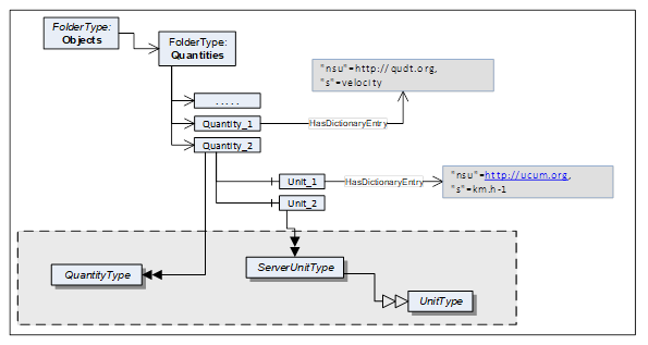
Figure 6 – Quantity model overview
Quantities is a standardized entry point to access all Quantities and their Units managed in the Server. It is formally defined in Table 32. All Objects of the QuantityType defined in clause 6.4.1, that are managed in the Server, shall be referenced directly from this Object with Organizes or a subtype of Organizes.
Table 32 – Quantities definition
|
Attribute |
Value |
|||
|
BrowseName |
Quantities |
|||
|
Description |
This Object is the entry point to quantities and their units managed in the Server. |
|||
|
References |
NodeClass |
BrowseName |
DataType |
TypeDefinition |
|
OrganizedBy by the Server Object defined in OPC 10000-5 |
||||
|
HasTypeDefinition |
ObjectType |
FolderType |
|
|
|
Conformance Units |
||||
|
Data Access Quantities Base |
||||
Syntax References represent established works of other organizations. Such works – among others – can define semantic information, topologies, a language for a code set, or dictionaries and facilitate the programmatic evaluation or the lookup of a quantity or unit e.g. in a dictionary or ontology. They can be publicly defined by standard bodies such as IEC or proprietary (e.g. vendor-specific dictionaries).
The Quantities and Unit Model provides a powerful way to relate quantities and units to such Syntax References using the Dictionary References model defined in OPC 10000-19.
Table 33 lists Syntax References that are applied in certain markets. This list can be extended in future versions. Vendors or organizations can also specify additional Syntax References.
An overview for each Syntax Reference in this table is provided in Annex C.
Table 33 – List of Syntax References
|
Common Name |
Syntax Reference URI |
Full Name |
|
UCUM |
https://ucum.org |
Unified Code for Units of Measure |
|
QUDT |
https://qudt.org |
Quantities, Units, Dimensions and Types Ontology |
|
IEC CDD |
https://cdd.iec.ch/ |
Common Data Dictionary |
|
UNECE |
https://unece.org/trade/uncefact/cl-recommendations |
Codes for Units of Measure Used in International Trade |
|
LATEX_SIUNITX |
https://www.namsu.de/Extra/pakete/Siunitx.html |
LaTeX SI Unit Extension |
HasDictionaryEntry is used to define the relationship to a Syntax Reference by referencing from quantity or unit Nodes to an instance of a SyntaxReferenceEntryType. Each quantity or unit instance can have zero, one or more such references.
Instances of SyntaxReferenceEntryType have a well-defined NodeId as defined in Table 34.
Table 34 – Definition of NodeId for instances of the SyntaxReferenceEntryType
|
Name |
Type |
Definition for instances of the SyntaxReferenceEntryType |
|
NodeId |
structure |
|
|
namespaceIndex |
UInt16 |
The NamespaceTable index for the Syntax Reference URI (see Table 33). |
|
Enum |
String |
|
|
identifier |
* |
The Syntax Reference identifier (SyntaxReferenceId), see 6.3.3 |
When calling the Browse Service for a Quantity or Unit Node, the response includes the HasDictionaryEntry Reference together with the well-defined NodeId for the SyntaxReferenceEntryType instance. The actual instance therefore is not required in the AddressSpace.
Figure 7 provides an example of References to external works.
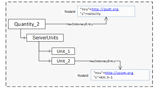
Figure 7 – References to external works
Table 35 defines the identifiers for each Syntax Reference.
Table 35 – List of Syntax Reference Identifiers
|
Common Name |
Identifier |
|
UCUM |
QuantityType instances: The UCUM Syntax ReferenceID for quantities shall include the prefix “quantityKind:” followed by the name of the quantity. |
|
UnitType instances: The UCUM SyntaxReferenceId for units shall include an expression based on the UCUM syntax making use of the symbols named in the “C/S” entry of the UCUM spec (https://ucum.org/ucum.html). Codes (expressions) for common units are defined in Annex B. |
|
|
QUDT |
QuantityType instances: The QUDT Syntax ReferenceID for quantities shall include the prefix “quantityKind:” followed by the name of the quantity as in https://www.qudt.org/doc/DOC_VOCAB-QUANTITY-KINDS.html. Example quantities are in C.2 |
|
UnitType instances: The QUDT Syntax ReferenceID for units shall include the prefix “unit:” followed by the name of the unit as in https://www.qudt.org/doc/DOC_VOCAB-UNITS.html. Example units are in C.2. |
|
|
IEC CDD |
QuantityType instances: The IEC CDD SyntaxReferenceId shall include the IRDI of the respective quantity. Example quantities are in C.4. |
|
UnitType instances: The IEC CDD SyntaxReferenceId shall include the IRDI of the respective unit. Example units are in C.4. |
|
|
UNECE |
QuantityType instances: There are no UNECE Syntax References for quantities. |
|
UnitType instances: The UNECE SyntaxReferenceId shall include the common code from “Codes for Units of Measurement” published by the “United Nations Centre for Trade Facilitation and Electronic Business” (see UNECE).
Example units are in C.3. |
|
|
LATEX_SIUNITX |
QuantityType instances: There are no LATEX_SIUNITX Syntax References for quantities. |
|
UnitType instances: The LATEX_SIUNITX SyntaxReferenceId shall include the leading slash, the keyword of the macro as well as the entire argument.
Example units are in C.5. |
The QuantityType defines a model for physical quantities. These are listed in the Quantites Folder. Each quantity has a ServerUnits Folder in which the units, referenced by EngineeringUnit Properties with HasEngineeringUnitDetails, are listed. Each ServerUnit can have a list of alternative units to which the Variable value can be converted.
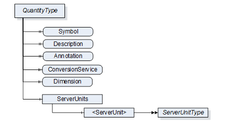
Figure 8 – QuantityType
It is illustrated in Figure 8 and formally defined in Table 36.
Table 36 – QuantityType definition
|
Attribute |
Value |
||||
|
BrowseName |
QuantityType |
||||
|
IsAbstract |
False |
||||
|
References |
NodeClass |
BrowseName |
DataType |
TypeDefinition |
Other |
|
Subtype of the BaseObjectType defined in OPC 10000-5 |
|||||
|
HasProperty |
Variable |
Symbol |
LocalizedText |
PropertyType |
O |
|
|
|
|
|
|
|
|
HasProperty |
Variable |
Annotation |
AnnotationDataType[] |
PropertyType |
O |
|
HasProperty |
Variable |
ConversionService |
UriString |
PropertyType |
O |
|
HasProperty |
Variable |
Dimension |
QuantityDimension |
PropertyType |
M |
|
HasComponent |
Object |
ServerUnits |
|
BaseObjectType |
M |
|
Conformance Units |
|||||
|
Data Access Quantities Base |
|||||
The Description Attribute should be used to expose a more verbose explanation of the QuantityType instance.
The Symbol Property is used for the symbol of the quantity (e.g. ‘l’ for length, ‘t’ for time, or ‘T’ for temperature).
Annotation allows naming annotations for a physical quantity. These Annotations are explanations of the physical quantity such as "relative" for a relative velocity. The AnnotationDataType is described in chapter 6.6.1.
For example, a VAC RMS measurement is the quadratic mean measurement of an AC voltage. We are using two annotation elements to represent it. Its Instance would contain the following values:
|
Annotation |
Discipline |
uri |
|
AC |
Electrical Engineering |
|
|
RMS |
Electrical Engineering |
ConversionService allows to name an external conversion service for the unit in which the client can have a conversion to a target unit performed.
Dimension describes the dimension of a physical quantity in power representation. Its DataType is described in chapter 6.6.4.
ServerUnits allows listing ServerUnits for a physical quantity. The ServerUnits are of ServerUnitType which is described in 6.4.2.
Syntax References: Instances of the QuantityType can identify the physical quantity in a specific external reference work using HasDictionaryEntry References – see 6.3.2.
The components of the QuantityType have additional subcomponents which are defined in Table 37.
Table 37 – QuantityType Additional Subcomponents
|
BrowsePath |
References |
NodeClass |
BrowseName |
DataType |
TypeDefinition |
Others |
|
ServerUnits |
HasComponent |
Object |
<ServerUnit> |
|
ServerUnitType |
MP |
The Units model describes the relations between UnitType, ServerUnitType and AlternativeUnitType.
The UnitType is the base class and defines details that are relevant of all derived types.
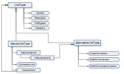
Figure 9 – Units model
It is formally defined in Table 38.
Table 38 – UnitType definition
|
Attribute |
Value |
||||
|
BrowseName |
UnitType |
||||
|
IsAbstract |
True |
||||
|
References |
NodeClass |
BrowseName |
DataType |
TypeDefinition |
Other |
|
Subtype of the BaseObjectType defined in OPC 10000-5 |
|||||
|
HasProperty |
Variable |
Symbol |
LocalizedText |
PropertyType |
M |
|
|
|
|
|
|
|
|
HasProperty |
Variable |
UnitSystem |
String |
PropertyType |
M |
|
HasProperty |
Variable |
Discipline |
String |
PropertyType |
O |
|
Conformance Units |
|||||
|
Data Access Quantities Base |
|||||
The DisplayName Attribute of each instance shall provide the name of the unit, e.g. “second”, “degree Celsius” or “square metre”. This matches the “description” field of the EUInformation structure (see 5.6.3.3).
The Description Attribute should be used to expose a more verbose explanation of the UnitType instance.
The Symbol Property is used for the symbol of the unit (e.g. "h" for hour or "m/s" for meter per second). If no symbol is defined for the unit, the DisplayName Attribute shall be used as symbol. Symbol matches the “displayName” field of the EUInformation structure (see 5.6.3.3).
The UnitSystem Property describes the system of units (e.g. ISQ) in which the unit is specified. If any of the well-known systems defined in Table 39 is used, the acronym in the column “UnitSystem” shall be used for the value of this Property.
Table 39 – Non-exhaustive list of well-known systems of units
|
UnitSystem |
System of units |
|
ISQ |
International System of Quantities (ISO/IEC 80000) Fully covers and thus replaces SI (ISO 1000) |
|
USCS |
US Customary Unit System |
|
ISU |
British imperial system of units |
|
MSU |
Myanmar Units of measurement |
|
TROY |
Troy units of weight |
|
CGS |
centimetre–gram–second system of units |
|
GAUSS |
Gaussian System of units |
|
FPS |
foot–pound–second system of units |
Syntax References: Instances of the UnitType can identify the unit in a specific external reference work using HasDictionaryEntry References – see 6.3.2.
Instances of ServerUnitType define the units utilizes in the Server. They are assigned to the proper Quantities. EngineeringUnit Properties can refer to it. It is formally defined in Table 40.
Table 40 – ServerUnitType definition
|
Attribute |
Value |
||||
|
BrowseName |
ServerUnitType |
||||
|
IsAbstract |
False |
||||
|
References |
NodeClass |
BrowseName |
DataType |
TypeDefinition |
Other |
|
Subtype of the UnitType |
|||||
|
HasComponent |
Object |
AlternativeUnits |
|
BaseObjectType |
O |
|
HasProperty |
Variable |
ConversionLimit |
ConversionLimitEnum |
PropertyType |
M |
|
HasComponent |
Object |
CoherentUnit |
|
UnitType |
O |
|
Conformance Units |
|||||
|
Data Access Quantities Base |
|||||
The optional Object AlternativeUnits contains Objects of the AlternativeUnitsType. These explicitly specify the units into which the conversion can be made.
The mandatory Property ConversionLimit indicates whether the ServerUnit can be converted. A distinction is made between NO_CONVERSION, LIMITED and UNLIMITED.
UNLIMITED means the client can perform conversions based on the rules defined by the given UnitSystem.
LIMITED conversion means that a conversion can not be performed by simply applying the rules defined by the given UnitSystem. Either only the conversions mentioned in the AlternativeUnits are to be used or the client requires application specific know-how for a conversion on his own.
NO_CONVERSION means that no conversion is allowed (e.g. for statistical values).
The CoherentUnit of a value is a derived unit that, for a given system of quantities and for a chosen set of base units, is a product of powers of base units, with the proportionality factor being one. Therefore it shall share the same UnitSystem as the ServerUnit.
The components of the ServerUnitType have additional subcomponents which are defined in Table 41.
Table 41 – ServerUnitType Additional Subcomponents
|
BrowsePath |
References |
NodeClass |
BrowseName |
DataType |
TypeDefinition |
Other |
|
AlternativeUnits |
HasComponent |
Object |
<AlternativeUnit> |
AlternativeUnitType |
MP |
The AlternativeUnitType describes alternative units to a ServerUnit. It is required to specify a conversion method for a value from the ServerUnit to this AlternativeUnit. It is formally defined in Table 42.
The use of conversions enables that a server and a client can work with different units and even in different systems of units. E.g. a server works with imperial units and a client uses metric units.
As a single server can distribute values to a number of clients with different needs the actual conversion has to be performed at client side.
Table 42 – AlternativeUnitType definition
|
Attribute |
Value |
||||
|
BrowseName |
AlternativeUnitType |
||||
|
IsAbstract |
False |
||||
|
References |
NodeClass |
BrowseName |
DataType |
TypeDefinition |
Other |
|
Subtype of the UnitType |
|||||
|
HasProperty |
Variable |
LinearConversion |
LinearConversionDataType |
PropertyType |
O |
|
HasProperty |
Variable |
MathMLConversion |
String |
PropertyType |
O |
|
HasProperty |
Variable |
MathMLInverseConversion |
String |
PropertyType |
O |
|
Conformance Units |
|||||
|
Data Access Alternative Units |
|||||
The Server shall provide either a LinearConversion or a MathMLConversion together with a corresponding MathMLInverseConversion. It can provide Linear and MathML conversions in parallel.
The optional Property LinearConversion represents a simple conversion according to the following formula. The values (a, b, c, d) are given in a Structure as defined in the LinearConversionDataType in chapter 6.6.2. The value x is published by the Server in the named server unit and y is the value converted into the named alternative unit.
![]()

Figure 10 – MathML example linear conversion
This also defines the inverse conversion to be used if a Client wants to write a value to the Server. The values (a, b, c, d) are given in a Structure as defined in the LinearConversionDataType in chapter 6.6.2. The value y1 is the value that the Client wants to write to the Server in the named alternative unit and x1 is the value the Client actually has to write to the Server instead
![]()

Figure 11 – MathML example inverse linear conversion
The optional Property MathMLConversion allows the specification of all kinds of conversion methods. The MathML syntax is used for this. Within the MathML expression X always stands for the value at the server side and Y for the value at the client side. An example (formula of the LinearConversion) looks as follows.
The SyntaxReferenceEntryType defined in Table 43 is used to represent Syntax References that use Syntax Reference specific IDs as unique identifiers.
Because of their well-defined NodeIds (see 6.3.2), instances of this type are not required in the AddressSpace.
Table 43 – SyntaxReferenceEntryType Definition
|
Attribute |
Value |
|||||
|
BrowseName |
SyntaxReferenceEntryType |
|||||
|
IsAbstract |
False |
|||||
|
References |
NodeClass |
BrowseName |
DataType |
TypeDefinition |
Other |
|
|
Subtype of the DictionaryEntryType defined in OPC 10000-19 |
||||||
|
HasProperty |
Variable |
CommonName |
String |
PropertyType |
M |
|
|
Conformance Units |
||||||
|
Data Access Quantity Syntax Reference |
||||||
CommonName shall be the corresponding field in Table 33.
The namespace for the NodeId and the BrowseName Attributes of instances of the SyntaxReferenceEntryType shall be the URI of the Syntax Reference as defined in Table 33.
The HasEngineeringUnitDetails is a concrete ReferenceType and can be used directly. It is a subtype of NonHierarchicalReferences.
The semantics of this ReferenceType is to link a Variable with EUInformation DataType to its more detailed AddressSpace representation Instance of the ServerUnitType ObjectType.
The SourceNode of References of this type shall be a Variable with EUInformation DataType.
The TargetNode of this ReferenceType shall be an Instance of the ServerUnitType ObjectType.
The Reference has to change if the value (the concrete EngineeringUnit) is changing. Clients can subscribe to the value and then need to rebrowse.
The HasEngineeringUnitDetails is formally defined in Table 44.
Table 44 – HasEngineeringUnitDetails definition
|
Attributes |
Value |
||
|
BrowseName |
HasEngineeringUnitDetails |
||
|
InverseName |
EngineeringUnitDetailsOf |
||
|
Symmetric |
False |
||
|
IsAbstract |
False |
||
|
References |
NodeClass |
BrowseName |
Comment |
|
Subtype of NonHierarchicalReferences defined in OPC 10000-5. |
|||
|
Conformance Units |
|||
|
Data Access Quantities Base |
|||
The HasQuantity is a concrete ReferenceType and can be used directly. It is a subtype of NonHierarchicalReferences.
The semantics of this ReferenceType is to link a Variable with EUInformation DataType to an Instance of the QuantityType ObjectType.
The SourceNode of References of this type shall be a Variable with EUInformation DataType (typically the EngineeringUnits Property).
The TargetNode of this ReferenceType shall be an Instance of the QuantityType ObjectType.
The HasQuantity is formally defined in Table 45.
Table 45 – HasQuantity definition
|
Attributes |
Value |
||
|
BrowseName |
HasQuantity |
||
|
InverseName |
QuantityOf |
||
|
Symmetric |
False |
||
|
IsAbstract |
False |
||
|
References |
NodeClass |
BrowseName |
Comment |
|
Subtype of NonHierarchicalReferences defined in OPC 10000-5. |
|||
|
Conformance Units |
|||
|
Data Access Quantities Base |
|||
This structure contains additions as explanation and specification of the physical quantity such as "relative" for a relative velocity. The structure is defined in Table 46.
Table 46 – AnnotationDataType Structure
|
Name |
Type |
Description |
|
AnnotationDataType |
structure |
Subtype of Structure defined in OPC 10000-5 |
|
Annotation |
String |
Names the annotation to give further information about value like how it is measured or where it originates from. |
|
Discipline |
String |
Gives a human readable classification of the physical quantity according to its field of application to allow grouping of values. These can be, for example, “Engineering”, “Finance” or similar. |
|
Uri |
String |
Names a source for deeper description of the annotation. |
Examples are given in Table 47.
Table 47 – AnnotationDataType examples
|
Name |
Values for a linear acceleration |
Values for AC voltage |
Values for DC voltage |
Values for AC RMS voltage |
|
AnnotationDataType |
|
|
|
|
|
Annotation |
linear |
AC |
DC |
RMS |
|
Discipline |
- |
Electrical Engineering |
Electrical Engineering |
Electrical Engineering |
|
Uri |
- |
https://www.britannica.com/science/alternating-current |
https://www.britannica.com/science/direct-current |
https://en.wikipedia.org/wiki/Root_mean_square |
Its representation in the AddressSpace is defined in Table 48.
Table 48 – AnnotationDataType definition
|
Attribute |
Value |
|||||
|
BrowseName |
AnnotationDataType |
|||||
|
IsAbstract |
False |
|||||
|
References |
NodeClass |
BrowseName |
DataType |
TypeDefinition |
Other |
|
|
Subtype of the Structure defined in OPC 10000-5 |
||||||
|
Conformance Units |
||||||
|
Data Access Quantities Base |
||||||
This structure contains a simple conversion according to the following formula. The factors (a = inititialAddend, b = multiplicand, c = divisor, d = finalAddend) are given in a Structure. X is the source value (in source unit) and f(x) the target value (in target unit). The structure is defined in Table 49.
![]()
The values of the structure can also be used for a simple inverse conversion. It can be used if a Client wants to write a value to the Server. The value y1 is the value that the Client wants to write to the Server in the named alternative unit and x1 is the value the Client actually has to write to the Server instead.
![]()
Table 49 – LinearConversionDataType Structure
|
Name |
Type |
Description |
|
LinearConversionDataType |
Structure |
Subtype of Structure defined in OPC 10000-5 |
|
InitialAddend |
Float |
The initial addend of linear conversion. |
|
Multiplicand |
Float |
The multiplicand of linear conversion. |
|
Divisor |
Float |
The divisor of linear conversion. |
|
FinalAddend |
Float |
The final addend of linear conversion. |
Its representation in the AddressSpace is defined in Table 48.
Table 50 – LinearConversionDataType Definition
|
Attribute |
Value |
|||||
|
BrowseName |
LinearConversionDataType |
|||||
|
IsAbstract |
False |
|||||
|
References |
NodeClass |
BrowseName |
DataType |
TypeDefinition |
Other |
|
|
Subtype of the Structure defined in OPC 10000-5 |
||||||
|
Conformance Units |
||||||
|
Data Access Alternative Units |
||||||
ConversionLimitEnum indicates whether the ServerUnit can be converted. A distinction is made between NO_CONVERSION, LIMITED and UNLIMITED. NO_CONVERSION means that no conversion is allowed (e.g. for statistical values). LIMITED conversion means that either only the conversions mentioned in the AlternativeUnits are to be used or the client requires specific know-how for the conversion. UNLIMITED means the conversion is simple and possible if the client knows the UnitSystem. The enumeration is defined in Table 51.
Table 51 – ConversionLimitEnum Items
|
Name |
Value |
Description |
|
NO_CONVERSION |
0 |
No conversion of the value allowed (e.g. statistical value). |
|
LIMITED |
1 |
Conversion only permitted on the basis of the conversions specified by the server, or if the client has the appropriate domain knowledge to perform an independent conversion. |
|
UNLIMITED |
2 |
Conversion on the basis of the specified unit according to the rules of the source system of units (e.g. SI / ISQ) and the coding system (e.g. UCUM) is permitted. |
Its representation in the AddressSpace is defined in Table 52.
Table 52 – ConversionLimitEnum Definition
|
Attribute |
Value |
|||||
|
BrowseName |
ConversionLimitEnum |
|||||
|
IsAbstract |
False |
|||||
|
References |
NodeClass |
BrowseName |
DataType |
TypeDefinition |
Other |
|
|
Subtype of the Enumeration type defined in OPC 10000-5 |
||||||
|
HasProperty |
Variable |
EnumStrings |
LocalizedText [] |
PropertyType |
|
|
|
Conformance Units |
||||||
|
Data Access Alternative Units |
||||||
The QuantityDimension Structure DataType describes the dimensionality of a kind of quantity in the context of a system of units. In the SI system of units, the dimensions of a kind of quantity are expressed as a product of the basic physical dimensions length (L), mass (M), time (T), current (I), absolute temperature (θ), amount of substance (N) and luminous intensity (J) as
![]() .
.
The rational powers of the dimensional exponents (α, β, γ, δ, ε, η, v), are positive, negative, or zero.
An additional dimensionless exponent is used for countable things that have no physical quantity assigned.
The QuantityDimension elements are defined in Table 53.
Table 53 – QuantityDimension DataType structure
|
Name |
Type |
Description |
|
QuantityDimension |
Structure |
|
|
MassExponent |
SByte |
Exponent of the dimension mass for the physical quantity. |
|
LengthExponent |
SByte |
Exponent of the dimension length for the physical quantity. |
|
TimeExponent |
SByte |
Exponent of the dimension time for the physical quantity. |
|
ElectricCurrentExponent |
SByte |
Exponent of the dimension electric current for the physical quantity. |
|
AmountOfSubstanceExponent |
SByte |
Exponent of the dimension amount of substance for the physical quantity. |
|
LuminousIntensityExponent |
SByte |
Exponent of the dimension luminous intensity for the physical quantity. |
|
AbsoluteTemperatureExponent |
SByte |
Exponent of the dimension absolute temperature for the physical quantity. |
|
DimensionlessExponent |
SByte |
Exponent for dimensionless quantities. |
Its representation in the AddressSpace is defined in Table 54.
Table 54 – QuantityDimension definition
|
Attribute |
Value |
|||||
|
BrowseName |
QuantityDimension |
|||||
|
IsAbstract |
False |
|||||
|
References |
NodeClass |
BrowseName |
DataType |
TypeDefinition |
Other |
|
|
Subtype of Structure defined in OPC 10000-5. |
||||||
|
Conformance Units |
||||||
|
Data Access Quantities Base |
||||||
For example, the dimension of the physical quantity kind
![]() ,
,
the dimension of the physical quantity kind force is
![]() ,
,
and the dimension of the physical quantity kind “things (e.g., screws) per time” is
![]() .
.
Table 55 – QuantityDimension examples
|
Name |
Values for speed |
Values for force |
Values for “things per time” |
|
QuantityDimension |
|
|
|
|
MassExponent |
0 |
1 |
0 |
|
LengthExponent |
1 |
1 |
0 |
|
TimeExponent |
-1 |
-2 |
-1 |
|
ElectricCurrentExponent |
0 |
0 |
0 |
|
AmoutOfSubstanceExponent |
0 |
0 |
0 |
|
LuminousIntensityExponent |
0 |
0 |
0 |
|
AbsoluteTemperatureExponent |
0 |
0 |
0 |
|
DimensionlessExponent |
0 |
0 |
1 |
The extended SI System of units includes derived units that are built as a product of base units. That makes it difficult to compare units as SI allows an unlimited number of “SI unit strings” to describe the same quantity.
![]()
All 3 are valid SI representations of the quantity “speed” and therefore share the same quantity dimensions. A specific representation of a unit is often used to express details how the unit was measured. The dimension structure makes it much easier to identify and compare the kind of quantity of EU values.
![]()
![]()
![]()
OPC 10000-4 specifies the complete set of services. The services needed for the purpose of DataAccess are:
· The View service set and Query service set to detect DataItems, and their Properties.
· The Attribute service set to read or write Attributes and in particular the value Attribute.
· The MonitoredItem and Subscription service set to set up monitoring of DataItems and to receive data change notifications.
The DataChangeFilter in OPC 10000-4 defines the conditions under which a data change notification shall be reported. This filter contains a deadbandValue which can be of type AbsoluteDeadband or PercentDeadband. OPC 10000-4 already specifies the behaviour of the AbsoluteDeadband. This sub-clause specifies the behaviour of the PercentDeadband type.
DeadbandType = PercentDeadband
For this type of deadband the deadbandValue is defined as the percentage of the EURange. That is, it applies only to AnalogItems with an EURange Property that defines the typical value range for the item. This range shall be multiplied with the deadbandValue and then compared to the actual value change to determine the need for a data change notification. The following pseudo code shows how the deadband is calculated:
DataChange if (absolute value
of (last cached value - current value) >
(deadbandValue/100.0) * ((high–low) of EURange)))
The range of the deadbandValue is from 0,0 to 100,0 per cent. Specifying a deadbandValue outside of this range will be rejected and reported with the StatusCode Bad_DeadbandFilterInvalid (see Table 56).
If the Value of the MonitoredItem is an array, then the deadband calculation logic shall be applied to each element of the array. If an element that requires a DataChange is found, then no further deadband checking is necessary and the entire array shall be returned.
This subclause defines additional codes and rules that apply to the StatusCode when used for Data Access values.
The general structure of the StatusCode is specified in OPC 10000-4 and includes a set of common operational result codes that also apply to Data Access.
Certain conditions under which a Variable value was generated are only valid for automation data and in particular for device data; they are similar, but are slightly more generic than the description of data quality in the various fieldbus specifications.
Table 56 contains codes with BAD severity which indicates a failure.
Table 57 contains codes with UNCERTAIN severity which indicates that the value has been generated under sub-normal conditions.
Table 58 contains GOOD (success) codes.
Note again, that these are the codes that are specific for Data Access and supplement the codes that apply to all types of data which are defined in OPC 10000-4.
Table 56 – Operation level result codes for BAD data quality
|
Symbolic Id |
Description |
|
Note - Bad is defined in OPC 10000-4. It shall be used when there is no special reason why the Value is bad. |
|
|
Bad_ConfigurationError |
There is a problem with the configuration that affects the usefulness of the value. |
|
Bad_NotConnected |
The variable should receive its value from some data source, but has never been configured to do so. |
|
Bad_DeviceFailure |
There has been a failure in the device/data source that generates the value that has affected the value. |
|
Bad_SensorFailure |
There has been a failure in the
sensor from which the value is derived by the device/data source. |
|
NOTE - Bad_NoCommunication is defined in OPC 10000-4. It shall be used when communications to the data source is defined, but not established, and there is no last known value available. |
|
|
Bad_OutOfService |
The source of the data is not operational. |
|
|
OPC UA requires that the Server shall return a Null value when the Severity is Bad. Therefore, the Fieldbus code “Bad_LastKnown” shall be mapped to Uncertain_NoCommunicationLastUsable. |
|
Bad_DeadbandFilterInvalid |
The specified PercentDeadband is not between 0.0 and 100.0 or a PercentDeadband is not supported, since an EURange is not configured. |
|
NOTE - Bad_WaitingForInitialData is defined in OPC 10000-4. |
|
Table 57 – Operation level result codes for UNCERTAIN data quality
|
Symbolic Id |
Description |
|
Note - Uncertain is defined in OPC 10000-4. It shall be used when there is no special reason why the Value is uncertain. |
|
|
Uncertain_ NoCommunicationLastUsable |
Communication to the data source has failed. The variable value is the last value that had a good quality and it is uncertain whether this value is still current. The server timestamp in this case is the last time that the communication status was checked. The time at which the value was last verified to be true is no longer available. |
|
Uncertain_ |
Whatever was updating this value has stopped doing so. This happens when an input variable is configured to receive its value from another variable and this configuration is cleared after one or more values have been received. This status/substatus is not used to indicate that a value is stale. Stale data can be detected by the client looking at the timestamps. |
|
Uncertain_SubstituteValue |
The value is an operational value that was manually overwritten. |
|
Uncertain_InitialValue |
The value is an initial value for a variable that normally receives its value from another variable. This status/substatus is set only during configuration while the variable is not operational (while it is out-of-service). |
|
Uncertain_ |
The value is at one of the sensor limits. The Limits bits define which limit has been reached. Also set if the device can determine that the sensor has reduced accuracy (e.g. degraded analyzer), in which case the Limits bits indicate that the value is not limited. |
|
Uncertain_ EngineeringUnitsExceeded |
The value is outside of the range of values defined for this parameter. The Limits bits indicate which limit has been reached or exceeded. |
|
Uncertain_SubNormal |
The value is derived from multiple sources and has less than the required number of Good sources. |
|
Uncertain_SimulatedValue |
The value is simulated. |
|
Uncertain_ |
The value possibly is not accurate due to a sensor calibration fault. |
|
Uncertain_ |
The value possibly is not accurate due to a configuration issue. |
Table 58 – Operation level result codes for GOOD data quality
|
Symbolic Id |
Description |
|
NOTE Good is defined in OPC 10000-4. It shall be used when there are no special conditions. |
|
|
Good_LocalOverride |
The value has been Overridden. Typically, this means the input has been disconnected and a manually-entered value has been "forced". |
The bottom 16 bits of the StatusCode are bit flags that contain additional information, but do not affect the meaning of the StatusCode. Of particular interest for DataItems is the LimitBits field. In some cases, such as sensor failure it can provide useful diagnostic information.
Servers that do not support Limit have to set this field to 0.
Annex A
(normative)
OPC COM DA to UA mapping
The OPC Foundation provides COM UA Wrapper and Proxy samples that act as a bridge between the OPC DA and the OPC UA systems.
The COM UA Wrapper is an OPC UA Server that wraps an OPC DA Server and with that enables an OPC UA Client to access information from the DA Server. The COM UA Proxy enables an OPC DA Client to access information from an OPC UA Server.
The mappings describe generic DA interoperability components. It is recommended that vendors use this mapping if they develop their own components, however, some applications can benefit from vendor specific mappings.
The COM UA Wrapper for instance can accept any Username/password and then try to impersonate this user by calling proper Windows services before connecting to the COM DA Server.
A.3 COM UA wrapper for OPC DA Server
A.3.1 Information Model mapping
A.3.1.1 General
OPC DA defines 3 elements in the address space: Branch, Item and Property. The COM UA Wrapper maps these types to the OPC UA types as described in Subclauses A.4.3.2 to A.4.3.4.
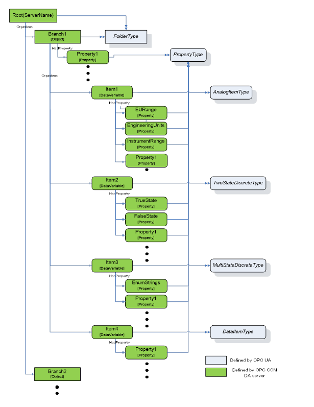
Figure A.12 – Sample OPC UA Information Model for OPC DA
A.3.1.2 Branch
DA Branches are represented in the COM UA Wrapper as Objects of FolderType.
The top-level branch (the root) should be represented by an Object where the BrowseName is the Server ProgId.
The OPC DA Address space hierarchy is discovered using the ChangeBrowsePosition from the Root and BrowseOPCItemIds to get the Branches, Items and Properties.
The name returned from the BrowseOPCItemIds enumString is used as the BrowseName and the DisplayName for each Branch. See also clause A.3.1.5.
The ItemId obtained using the GetItemID is used as a part of the NodeId for each Branch. See also clause A.3.1.5.
An OPC UA Folder representing a DA Branch uses the Organizes References to reference child DA Branches and uses HasComponent References for DA Leafs (Items). It is acceptable for customized wrappers to use a sub-type of these ReferenceTypes.
A.3.1.3 Item
DA items (leafs) are represented in the COM UA Wrapper as Variables. The VariableType depends on the existance of special DA properties as follows:
· AnalogItemType: An item in the DA server that has High EU and Low EU properties or its EU Type property is Analog is represented as Variable of AnalogItemType in the COM UA Wrapper. The AnalogItemType has the following Properties:
o EURange: The values of the High EU and Low EU properties of the DA Item are assigned to the EURange Property
o EngineeringUnits: The value of the Engineering Unit property of the DA Item are assigned to the EngineeringUnits Property.
o InstrumentRange: The values of the High IR and Low IR properties of the DA Item are assigned to the InstrumentRange Property
· TwoStateDiscreteType: An item in DA server that has Open Label and Close Label properties is represented as Variable of TwoStateDiscreteType in the COM UA Wrapper. The TwoStateDiscreteType has the following Properties
o TrueState: The value of the Close Label property of the DA item is assigned to the TrueState Property.
o FalseState: The value of the Open Label property of the DA item is assigned to the FalseState Property.
· MultiStateDiscreteType: An item in the DA server that has its EU Type property as enumerated is represented as Variable of MultiStateDiscreteType in the COM UA Wrapper. The MultiStateDiscreteType has the following Property:
o EnumStrings: The enumerated values of the EUInfo Property of the DA item are assigned to the EnumStrings Property.
· DataItemType: An item in the DA Server that is not any of the above types is represented as Variable of DataItemType in the COM UA Wrapper.
Below are mappings that are common for all item types
· The name of the item in the DA Server is used as the BrowseName and the DisplayName for the Node in the COM UA Wrapper. See also clause A.3.1.5.
· The ItemId in the DA server is used as a part of the NodeId for the Node. See also clause A.3.1.5.
· TimeZone property in the DA server is represented by a TimeZone Property.
· The Description property value in the DA server is assigned to the Description Attribute.
· The DataType property value in the DA server is assigned to the DataType Attribute.
· If the item in the DA server is an array, the ValueRank Attribute is set as OneOrMoreDimensions. If not, it is set to Scalar.
· The AccessLevel Attribute is set with the AccessRights value in the DA server:
o OPC_READABLE -> Readable
o OPC_WRITABLE -> Writable
Note that the same values are also set for the UserAccessLevel in the COM UA Wrapper.
· The ScanRate property value in the DA server is assigned to the MinimumSamplingInterval Attribute.
Any Properties added to a Node in the COM UA Wrapper are referenced using the HasProperty ReferenceType.
A.3.1.4 Property
A property in the DA server is represented in the COM UA Wrapper as a Variable with TypeDefinition as PropertyType.
The properties for an item are retrieved using the QueryAvailableProperties call in the DA server.
Below are mappings of the property details to the OPC UA Property:
· The description of a property in the DA server is used as the BrowseName and the DisplayName of the Node in the COM UA Wrapper.
· The PropertyID and ItemID (if they exist for the property) in the DA server are used as a part of the NodeID for the node in the COM UA Wrapper.
· The DataType value in the DA server is used as value for the DataType Attribute of the Property in the COM UA Wrapper.
· If the property value in the DA server is an array, the ValueRank Attribute of the Property is set to OneOrMoreDimensions. Otherwise, it is set to Scalar.
· If the property has an ItemID in the DA server, then the AccessLevel attribute for the Node is set to ReadableOrWriteable. If not, it is set to Readable.
Table A.59 shows the mapping between the common OPC COM DA properties to the OPC UA Node attributes/properties.
Table A.59 – OPC COM DA to OPC UA Properties mapping
|
Property Name (PropertyID) of OPC COM DA |
OPC UA Information Model |
OPC UA DataType |
|
Access Rights (5) |
AccessLevel Attribute |
Int32 |
|
EU Units (100) |
EngineeringUnits Property |
String |
|
Item Description (101) |
Description Attribute |
String |
|
High EU (102) |
EURange Property |
Double |
|
Low EU (103) |
EURange Property |
Double |
|
High Instrument Range (104) |
InstrumentRange Property |
Double |
|
Low Instrument Range (105) |
InstrumentRange Property |
Double |
|
Close Label (106) |
TrueState Property |
String |
|
Open Label (107) |
FalseState Property |
String |
|
Other Properties (include Vendor specific Properties) |
PropertyType |
Based on the DataType of the Property |
A.3.1.5 BrowseName and DisplayName Mapping
As described above, both the OPC UA Browsename and Displayname for Nodes representing COM DA Branches and Leafs are derived from the name of the corresponding item in the COM DA Server.
This name can only be acquired by using the COM DA Browse Services. In OPC UA, however, the BrowseName and DisplayName are Attributes that Clients can ask for at any time. There are several options to support this in a Wrapper but all of them have pros and cons. Here are some popular implementation options:
a. Allow browsing the complete COM DA Address Space and then build and persist an offline copy of it. Resolve the BrowseName by scanning this offline copy.
o Pro: The ItemID can be used as is for the OPC UA NodeId.
o Con: The initial browse can take a while and can have to be repeated for COM DA Servers with a dynamic Address Space.
b. Create OPC UA NodeId values that include both the COM DA ItemID and the Item name. When the OPC UA Client passes such a NodeId to read the BrowseName or DisplayName Attribute, the wrapper can easily extract the name from the NodeId value.
o Pro: Efficient and reliable.
o Con: The NodeId will not represent the ItemId. It becomes difficult for human users to match the two IDs.
c. A number of COM DA Servers use ItemIDs that consist of a path where the path elements are separated with a delimiter and the last element is the item name. Wrappers can provide ways to configure the delimiter so that they can easily extract the item name.
o Pro: Efficient and reliable. The ItemID can be used as is for the OPC UA NodeId.
o Con: Not a generic solution. Only works for specific COM-DA Servers.
For wrappers that are custom to a specific Server, knowledge of the COM DA server address space can result in other optimizations or short cuts (i.e. the server will always have a certain schema / naming sequence etc.).
A.3.2.1 General
In a DA server, Automation Data is represented by Value, Quality and Time Stamp for a Tag.
The COM UA Wrapper maps the VQT data to the Data Value and Diagnostic Info structures.
The Error codes returned by the DA server are based on the HRESULT type. The COM UA Wrapper maps this error code to an OPC UA Status Code. Figure A.13 illustrates this mapping.
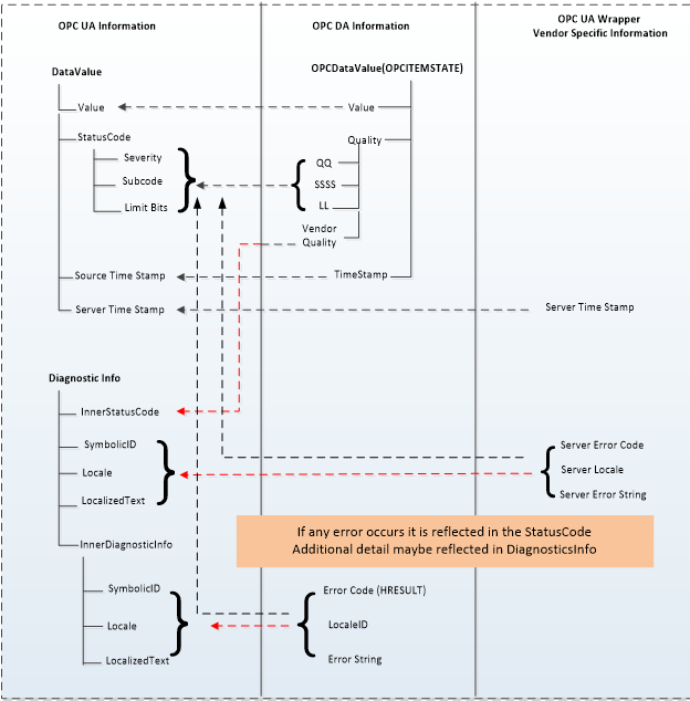
Figure A.13 – OPC COM DA to OPC UA data and error mapping
A.3.2.2 Value
The data values in the DA server are represented as Variant data type. The COM UA Wrapper converts them to the corresponding OPC UA DataType. The mapping is shown in Table A.60:
Table A.60 – DataTypes and mapping
|
Variant Data Type (In DA server) |
OPC UA Data type Mapping in COM UA Server (DataValue structure) |
|
VT_I2 |
Int16 |
|
VT_I4 |
Int32 |
|
VT_R4 |
Float |
|
VT_R8 |
Double |
|
VT_BSTR |
String |
|
VT_BOOL |
Boolean |
|
VT_UI1 |
Byte |
|
VT_I1 |
SByte |
|
VT_UI2 |
UInt16 |
|
VT_UI4 |
UInt32 |
|
VT_I8 |
Int64 |
|
VT_UI8 |
UInt64 |
|
VT_DATE |
Double |
|
VT_DECIMAL |
Decimal |
|
VT_ARRAY |
Array of OPC UA types |
.
A.3.2.3 Quality
The Quality of a Data Value in the DA server is represented as a 16 bit value where the lower 8 bits is of the form QQSSSSLL (Q: Main Quality, S: Sub Status, L: Limit) and higher 8 bits is vendor specific.
The COM UA Wrapper maps the DA server to the OPC UA Status code as shown in Figure A.14:
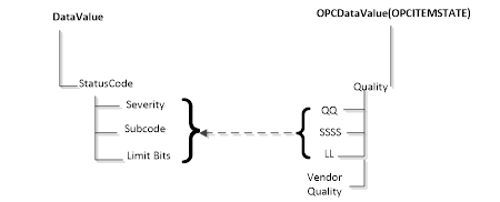
Figure A.14 – Status Code mapping
The primary quality is mapped to the Severity field of the Status code. The Sub Status is mapped to the SubCode and the Limit is mapped to the Limit Bits of the Status Code.
Please note that the Vendor quality is currently discarded.
Table A.61 shows a mapping of the OPC COM DA primary quality mapping to OPC UA status code
Table A.61 – Quality mapping
|
OPC DA Primary Quality (Quality & Sub status QQSSSS) |
OPC UA Status Code |
|
GOOD |
Good |
|
LOCAL_OVERRIDE |
Good_LocalOverride |
|
UNCERTAIN |
Uncertain |
|
SUB_NORMAL |
Uncertain_SubNormal |
|
SENSOR_CAL |
Uncertain_SensorNotAccurate |
|
EGU_EXCEEDED |
Uncertain_EngineeringUnitsExceeded |
|
LAST_USABLE |
Uncertain_LastUsableValue |
|
BAD |
Bad |
|
CONFIG_ERROR |
Bad_ConfigurationError |
|
NOT_CONNECTED |
Bad_NotConnected |
|
COMM_FAILURE |
Bad_NoCommunication |
|
DEVICE_FAILURE |
Bad_DeviceFailure |
|
SENSOR_FAILURE |
Bad_SensorFailure |
|
LAST_KNOWN |
Bad_OutOfService |
|
OUT_OF_SERVICE |
Bad_OutOfService |
|
WAITING_FOR_INITIAL_DATA |
Bad_WaitingForInitialData |
A.3.2.4 Timestamp
The Timestamp provided for a value in the DA server is assigned to the SourceTimeStamp of the DataValue in the COM UA Wrapper.
The ServerTimeStamp in the DataValue is set to the current time by the COM UA Wrapper at the start of the Read Operation.
The COM UA Wrapper supports performing Read operations to DA servers of versions 2.05a and 3.
For version 2.05a, the COM UA wrapper creates a Group using the IOPCServer::AddGroup method and adds the items whose data is to be read to the Group using IOPCItemMgmt::AddItems method. The Data is retrieved for the items using the IOPCSyncIO::Read method. The VQT for each item is mapped to the DataValue structure as shown in Figure A.13. Please note that only Read from Device is supported for this version. The “maxAge” parameter is ignored.
For version 3, the COM UA Wrapper uses the IOPCItemIO::Read to retrieve the data. The VQT for each item is mapped to the DataValue structure as shown in Figure A.13. The Read supports both the Read from Device and Cache and uses the “maxAge” parameter.
If there are errors for the items in the Read from the DA server, then these are mapped to the StatusCode of the DataValue in the COM UA Wrapper.
The mapping of the OPC COM DA Read Errors code to OPC UA Status code (in the COM UA Wrapper) is shown in Table A.62:
Table A.62 – OPC DA Read error mapping
|
OPC DA Error ID |
OPC UA Status Code |
|
OPC_E_BADRIGHTS |
Bad_NotReadable |
|
E_OUTOFMEMORY |
Bad_OutOfMemory |
|
OPC_E_INVALIDHANDLE |
Bad_NodeIdUnknown |
|
OPC_E_UNKNOWNITEMID |
Bad_NodeIdUnknown |
|
E_INVALIDITEMID |
Bad_NodeIdInvalid |
|
E_INVALID_PID |
Bad_AttributeIdInvalid |
|
E_ACCESSDENIED |
Bad_OutOfService |
|
Others |
Bad_UnexpectedError |
The COM UA Wrapper supports performing Write operations to DA servers of versions 2.05a and 3.
For version 2.05a, the COM UA wrapper creates a Group using the IOPCServer::AddGroup method and adds the items whose data is to be written using IOPCItemMgmt::AddItems method. The value is written for the items using the IOPCSyncIO::Write method. Note that if the StatusCode or TimeStamps (Source or Server) is specified to be written for the item then the COM UA Wrapper returns a BadWriteNotSupported Status code for the item.
For version 3, the COM UA Wrapper uses the IOPCItemIO::WriteVQT data including StatusCode and TimeStamp. If a SourceTimeStamp is provided, this timestamp is used for the Write else the ServerTimeStamp is used.
If there are errors for the items in the Write from the DA server, then these are mapped to the StatusCode for the corresponding item.
The mapping of the OPC COM DA Write Errors code to OPC UA Status code (in the COM UA Wrapper) is shown in Table A.63:
Table A.63 – OPC DA Write error code mapping
|
OPC DA Error ID |
OPC UA Status Code |
|
E_BADRIGHTS |
Bad_NotWritable |
|
DISP_E_TYPEMISMATCH |
Bad_TypeMismatch |
|
E_BADTYPE |
Bad_TypeMismatch |
|
E_RANGE |
Bad_OutOfRange |
|
DISP_E_OVERFLOW |
Bad_OutOfRange |
|
E_OUTOFMEMORY |
Bad_OutOfMemory |
|
E_INVALIDHANDLE |
Bad_NodeIdUnknown |
|
E_UNKNOWNITEMID |
Bad_NodeIdUnknown |
|
E_INVALIDITEMID |
Bad_NodeIdInvalid |
|
E_INVALID_PID |
Bad_NodeIdInvalid |
|
E_NOTSUPPORTED |
Bad_WriteNotSupported |
|
S_CLAMP |
Good_Clamped |
|
Others |
Bad_UnexpectedError |
A subscription is created in the DA server when a MonitoredItem is created in the COM UA Wrapper.
The SamplingInterval and the Deadband value are used for the subscription to setup a periodic data change call back on the COM UA Wrapper. Note that only the PercentDeadbandType is supported by the COM UA Wrapper.
The VQT for each item is mapped to the DataValue structure as shown in Figure A.13 and published to the client by the COM UA Wrapper periodically.
The mapping of the OPC COM DA Read Errors code to OPC UA Status code (in the COM UA Wrapper) is the same as the Read mapping in Figure A.13.
A.4 COM UA proxy for DA Client
The Data Access COM UA Proxy is a COM Server combined with a UA Client. It maps the Data Access address space of UA Data Access Server into the appropriate COM Data Access objects.
Clauses A.4.1 through A.4.6 identify the design guidelines and constraints used to develop the Data Access COM UA Proxy provided by the OPC Foundation. In order to maintain a high degree of consistency and interoperability, it is strongly recommended that vendors, who choose to implement their own version of the Data Access COM UA Proxy, follow these same guidelines and constraints.
The Data Access COM Client simply needs to address how to connect to the UA Data Access Server. Connectivity approaches include the one where Data Access COM Clients connect to a UA Data Access Server with a CLSID just as if the target Server were a Data Access COM Server. However, the CLSID can be considered virtual since it is defined to connect to intermediary components that ultimately connect to the UA Data Access Server. Using this approach, the Data Access COM Client calls co-create instance with a virtual CLSID as described above. This connects to the Data Access COM UA Proxy components. The Data Access COM UA Proxy then establishes a secure channel and session with the UA Data Access Server. As a result, the Data Access COM Client gets a COM Data Access Server interface pointer.
A.4.2 Information Model and Address Space mapping
A.4.2.1 General
OPC UA defines 8 Node Class types in the address space Object, Variable, Method, ObjectType, VariableType, ReferenceType, DataType, View. The COM UA Proxy maps only the nodes of Node Class types Object, Variable to the OPC DA types as shown in the figure below. Only the nodes under the Objects node are considered for the COM UA Proxy address space and others such as Types, Views are not mapped.
Figure A.15 shows an example mapping of OPC DA to OPC UA information.
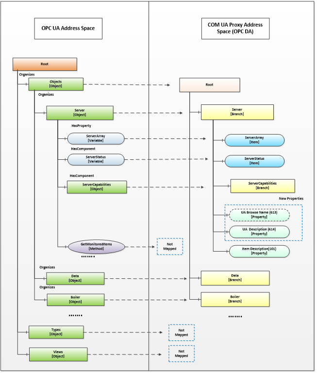
Figure A.15 – Sample OPC DA mapping of OPC UA Information Model and Address Space
A.4.2.2 Object Nodes
A node of Object Node class in the OPC UA server is represented in the Data Access COM UA Proxy as a Branch.
The root of the Data Access COM UA Proxy is the Objects folder of the OPC UA Server.
The OPC UA Address space hierarchy is discovered using the Browse Service for the Objects Node using the following filters:
· BrowseDirection as Forward
· ReferenceTypeId as Organizes and HasChild.
· IncludeSubtypes as True
· NodeClassMask as Object and Variable
The DisplayName of the OPC UA node is used as the Name for each Branch in the Data Access COM UA Proxy
Each Branch in the Data Access COM UA Proxy is assigned 3 properties:
· UA Browse Name (Property ID: 613): The value of the BrowseName attribute of the node in the OPC UA Server is assigned to this property.
· UA Description (Property ID: 614): The value of the Description attribute of the node in the OPC UA Server is assigned to this property, if a Description attribute is provided.
· Item Description (Property ID: 101): The value of the DisplayName attribute of the node in the OPC UA Server is assigned to this property.
NOTE COM DA Clients typically display the ItemID and the Item Description. Since the ItemID generated by the UA Proxy can be particularly difficult to read and understand, proxies can use the DisplayName as value for the Item Description Property as it will be easier to understand by a human user.
A.4.2.3 Variable Nodes
A node of Variable Node class in the OPC UA server is represented in the Data Access COM UA Proxy as an Item.
The DisplayName of the OPC UA node is used as the Name for each Item in the Data Access COM UA Proxy.
The NodeId of the OPC UA node is used as the ItemId for each Item in the Data Access COM UA Proxy. But the ‘=’ character is replaced with ‘-’ in the string. E.g. NodeId: ns=4,i=10, ItemID = “ns-4;i-10” or NodeId: ns=4,s=FL102, ItemID = “ns-4,s-FL102”
Each Item in the Data Access COM UA Proxy is assigned the following properties based on the node attributes or its references:
Standard Properties:
· Item Canonical Data Type (Property ID: 1): The combined value of the DataType attribute and the ValueRank attribute of the node in the OPC UA Server is assigned to this property (see A.4.3.2).
· Item Value (Property ID: 2): The value of the Value attribute of the node in the OPC UA Server is assigned to this property. Details on Value mapping are in A.4.3.2
· Item Quality (Property ID: 3): The StatusCode of the Value obtained for the node in the OPC UA Server is assigned to this property. Details on Quality mapping are in A.4.3.3
· Item Timestamp (Property ID: 4): The SourceTimestamp or ServerTimestamp of the Value obtained for the node in the OPC UA Server is assigned to this property. Details on Timestamp mapping are in A.4.3.4
· Item Access Rights (Property ID: 5): The value of the AccessLevel attribute of the node in the OPC UA Server is assigned to this property based on the following mapping:
o CurrentRead -> OPC_READABLE
o CurrentWrite -> OPC_WRITABLE
The other AccessLevel provided by OPC are ignored
· Server Scan Rate (Property ID: 6): The value of the MinimumSamplingInterval attribute of the node in the OPC UA Server is assigned to this property.
· Item EU Type (Property ID: 7): The EU Type value is assigned based on the references of the node in the OPC UA Server:
· Analog(1) : if the node in the OPC UA Server references a EURange property node, then it is assigned the Analog EU Type.
· Enumerated(2): if the node in the OPC UA Server references a EnumStrings property node, then it is assigned the Enumerated EU Type.
· Empty(0): For a node in the OPC UA Server that does not meet above criteria, the type is set as 0 (Empty)
· EU Info (Property ID: 8): if the node in the OPC UA Server references an EnumStrings property node, then the enumerated values of the property node is assigned to this property.
· EU Units (Property ID: 100): if the node in the OPC UA Server references a EngineeringUnits property node, then the value of the EngineeringUnits property node is assigned the EU Units property.
· Item Description (Property ID: 101): The value of the DisplayName attribute of the node in the OPC UA Server is assigned to this property.
· High EU (Property ID: 102): if the node in the OPC UA Server references a EURange property node, then the ‘High’ value of the property node is assigned to this property.
· Low EU (Property ID: 103): if the node in the OPC UA Server references a EURange property node, then the ‘Low’ value of the property node is assigned to this property.
· High Instrument Range (Property ID: 104): if the node in the OPC UA Server references an InstrumentRange property node, then the ‘High’ value of the property node is assigned to this property.
· Low Instrument Range (Property ID: 105): if the node in the OPC UA Server references an InstrumentRange property node, then the ‘Low’ value of the property node is assigned to this property.
· Contact Close Label (Property ID: 106): if the node in the OPC UA Server references a FalseState property node, then the value of the property node is assigned to this property.
· Contact Open Label (Property ID: 107): if the node in the OPC UA Server references a TrueState property node, then the value of the property node is assigned to this property.
· Item Time Zone (Property ID: 108): if the node in the OPC UA Server references a TimeZone property node, then the ‘Offset’ value of the property node is assigned to this property.
New Properties:
· UA BuiltIn Type (Property ID: 610): The identifier value of the DataType node associated with the DataType attribute of the node in the OPC UA Server is assigned to this property.
· UA Data Type Id (Property ID: 611): The complete NodeId value (namespace and identifier) of the DataType node associated with the DataType attribute of the node in the OPC UA Server is assigned to this property.
· UA Value Rank (Property ID: 612): The value of the ValueRank attribute of the node in the OPC UA Server is assigned to this property.
· UA Browse Name (Property ID: 613): The value of the BrowseName attribute of the node in the OPC UA Server is assigned to this property.
· UA Description (Property ID: 614): The value of the Description attribute of the node in the OPC UA Server is assigned to this property.
A.4.2.4 Namespace Indices
For generating ItemIDs, the Proxy uses Namespace Indices. To assure that Clients can persist these ItemIDs, the Namespace Indices must never change. To accomplish this the Proxy has to persist its Namespace Table and only append entries but never change existing ones.
The Proxy also has to provide a translation from the current Namespace Table in the Server to the persisted Namespace Table.
If you move or copy the Proxy to another machine, the Namespace Table has to be copied to this machine as well.
A.4.3.1 General
In an OPC UA Server, Automation Data is represented as a Data Value and and status, in addition additional error data can be provided via Diagnostic Info for a tag
The COM UA Proxy maps the Data Value structure into VQT data and error code.
For successful operations(StatusCode of Good and Uncertain), the COM UA Proxy maps the Status Code of the DataValue to the OPC DA Quality But in case of error(StatusCode of Bad), the Status Code is mapped to the OPC DA Error code.
The StatusCode in the Diagnostic Info returned by the OPC UA Server are mapped to OPC DA Error codes. Figure A.16 illustrates this mapping.
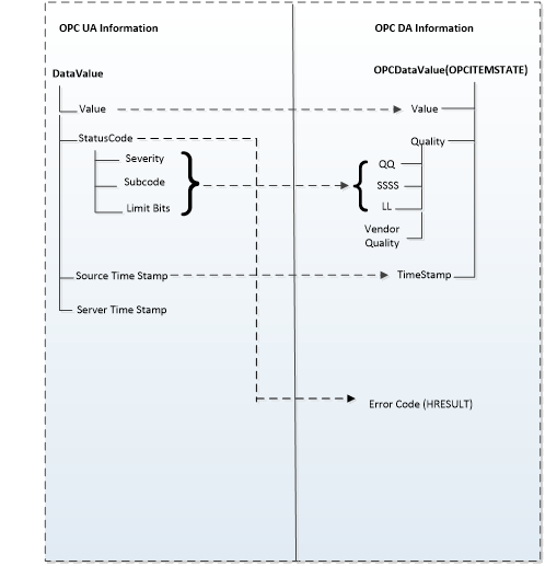
Figure A.16 – OPC UA to OPC DA data & error mapping
The COM UA Proxy converts the OPC UA Data Value to the corresponding OPC DA Variant type. The mapping is shown in Table A.64. For DataTypes that are subtypes of an existing base DataType the conversion for the Base DataType is used.
Table A.64 – DataTypes and Mapping
|
OPC UA Data type (In UA Server) |
Variant Data Type (In DA server) |
|
Int16 |
VT_I2 |
|
Int32 |
VT_I4 |
|
Float |
VT_R4 |
|
Double |
VT_R8 |
|
Decimal |
VT_DECIMAL |
|
String |
VT_BSTR |
|
Boolean |
VT_BOOL |
|
Byte |
VT_UI1 |
|
SByte |
VT_I1 |
|
UInt16 |
VT_UI2 |
|
UInt32 |
VT_UI4 |
|
Int64 |
VT_I8 |
|
UInt64 |
VT_UI8 |
|
Guid |
VT_BSTR |
|
DateTime |
VT_DATE |
|
NodeId |
VT_BSTR |
|
XmlElement |
VT_BSTR |
|
ExpandedNodeId |
VT_BSTR |
|
QualifiedName |
VT_BSTR |
|
LocalizedText |
VT_BSTR |
|
StatusCode |
VT_UI4 |
|
ExtensionObject |
Array of VT_UI1 |
|
Array of above OPC UA types |
Array of corresponding Variant type |
The Quality of a Data Value in the OPC UA Server is represented as a StatusCode.
The COM UA Proxy maps the Severity, Subcode and the limit bits of the OPC UA Status code to the lower 8 bits of the OPC DA Quality structure (of the form QQSSSSLL). Figure A.17 illustrates this mapping.

Figure A.17 – OPC UA Status Code to OPC DA quality mapping
The Severity field of the Status code is mapped to the primary quality. The SubCode is mapped to the Sub Status and the Limit Bits are mapped to the Limit field.
Table A.65 shows a mapping of the OPC UA status code to OPC DA primary quality
Table A.65 – Quality mapping
|
OPC UA Status Code |
OPC DA Primary Quality (Quality & Sub status QQSSSS) |
|
Good |
GOOD |
|
Good_LocalOverride |
LOCAL_OVERRIDE |
|
Uncertain |
UNCERTAIN |
|
Uncertain_SubNormal |
SUB_NORMAL |
|
Uncertain_SensorNotAccurate |
SENSOR_CAL |
|
Uncertain_EngineeringUnitsExceeded |
EGU_EXCEEDED |
|
Uncertain_LastUsableValue |
LAST_USABLE |
|
Bad |
BAD |
|
Bad_ConfigurationError |
CONFIG_ERROR |
|
Bad_NotConnected |
NOT_CONNECTED |
|
Bad_NoCommunication |
COMM_FAILURE |
|
Bad_OutOfService |
OUT_OF_SERVICE |
|
Bad_DeviceFailure |
DEVICE_FAILURE |
|
Bad_SensorFailure |
SENSOR_FAILURE |
|
Bad_WaitingForInitialData |
WAITING_FOR_INITIAL_DATA |
If available, the SourceTimestamp of the DataValue in the OPC UA Server is assigned to the Timestamp for the value in the COM UA Proxy. If SourceTimestamp is not available, then the ServerTimestamp is used.
The COM UA Proxy converts all the ItemIds in the Read into valid NodeIds by replacing the ‘-’ with ‘=’ and calls the OPC UA Read Service for the Value Attribute.
If the Read Service call is successful then DataValue for each node is mapped to the VQT for each item as shown in Figure A.16.
If the Read Service call fails or If there are errors for some of the Nodes, then the StatusCodes of these Nodes are mapped to the error code by the COM UA Proxy.
The mapping of the OPC UA Status code to OPC DA Read Error code (in the COM UA Proxy) is shown in Table A.66:
Table A.66 – OPC UA Read error mapping
|
OPC UA Status Code |
OPC DA Error ID |
|
Bad_OutOfMemory |
E_OUTOFMEMORY |
|
Bad_NodeIdInvalid |
E_INVALIDITEMID |
|
Bad_NodeIdUnknown |
E_UNKNOWNITEMID |
|
Bad_NotReadable |
E_BADRIGHTS |
|
Bad_UserAccessDenied |
E_ACCESSDENIED |
|
Bad_AttributeIdInvalid |
E_INVALIDITEMID |
|
Bad_UnexpectedError |
E_FAIL |
|
Bad_InternalError |
E_FAIL |
|
Bad_SessionClosed |
E_FAIL |
|
Bad_TypeMismatch |
E_BADTYPE |
The COM UA Proxy converts all the ItemIds in the Write into valid NodeIds by replacing the ‘-’ with ‘=’. It converts the Value, Quality and Timestamp (VQT) to a DataValue structure as per the mapping in Figure A.16. and calls the OPC UA Write Service for the Value Attribute.
If the Write Service call fails or if there are errors for some of the Nodes, then the StatusCodes of these Nodes are mapped to the error code by the COM UA Proxy.
The mapping of the OPC UA Status code to OPC DA Write Error code (in the COM UA Proxy) is shown in Table A.67:
Table A.67 – OPC UA Write error code mapping
|
OPC UA Status Code |
OPC DA Error ID |
|
Bad_TypeMismatch |
E_BADTYPE |
|
Bad_OutOfMemory |
E_OUTOFMEMORY |
|
Bad_NodeIdInvalid |
E_INVALIDITEMID |
|
Bad_NodeIdUnknown |
E_UNKNOWNITEMID |
|
Bad_NotWritable |
E_BADRIGHTS |
|
Bad_UserAccessDenied |
E_ACCESSDENIED |
|
Bad_AttributeIdInvalid |
E_UNKNOWNITEMID |
|
Bad_WriteNotSupported |
E_NOTSUPPORTED |
|
Bad_OutOfRange |
E_RANGE |
The COM UA Proxy creates a Subscription in the OPC UA Server when a Group is created. The Name, Active flag, UpdateRate parameters of the Group are used while creating the subscription.
The COM UA Proxy Creates Monitored Items in the OPC UA Server when items are added to the Group.
Following parameters and filters are used for creating the monitored items:
· The ItemIds are converted to valid NodeIds by replacing the ‘-’ with ‘=’.
· Data Change Filter is used for Items with EU type as Analog:
· Trigger = STATUS_VALUE
· If DeadBand value is specified for the Group, the;
o DeadbandType = Percent
o DeadbandValue = deadband specified for the group.
The COM UA Proxy calls the Publish Service of the OPC UA Server periodically and sends any data changes to the client.
Annex B
(normative)
UCUM Symbols
This Annex provides an excerpt from the UCUM Specification available at https://ucum.org.
The Unified Code for Units of Measure (UCUM), also known as the “UCUM Specification”, is copyright ©1999-2021, Regenstrief Institute, Inc. All rights reserved.
The UCUM license is available in https://ucum.org/license. This license includes a disclaimer of warranties.
UCUM can represent any number of valid units derived from 7 basic units. To that end, the standard combines various components:
· Basic units
o metre (m, length)
o second (s, time)
o gram (g, mass)
o radian (rad, angle)
o Kelvin (K, temperature)
o Coulomb (C, electric charge)
o candela (cd, luminous intensity)
· derived units with conversion factors and formulas for the reduction to base units
· prefixes, i.e. a list of 30 standard prefixes to generate multiples (e.g. k for kilo, multiplier 10³) or fractions (e.g. d for deci, multiplier 10-1) of measurement units
· symbols and operators as well as syntax rules for their combination as follows:
|
<sign> |
::= |
“+” | “-” |
|
<digit> |
::= |
“0” | “1” | “2” | “3” | “4” | “5” | “6” | “7” | “8” | “9” |
|
<digits> |
::= |
<digit><digits> | <digit> |
|
<factor> |
::= |
<digits> |
|
<exponent> |
::= |
<sign><digits> | <digits> |
|
<simple-unit> |
::= |
<ATOM-SYMBOL> | <PREFIX-SYMBOL><ATOM-SYMBOL[metric]> |
|
<annotatable> |
::= |
<simple-unit><exponent> | <simple-unit> |
|
<component> |
::= |
<annotatable><annotation> |
|
<term> |
::= |
<term>“.”<component> | <term>“/”<component> | <component> |
|
<main-term> |
::= |
“/”<term> | <term> |
|
<annotation> |
::= |
“{”<ANNOTATION-STRING>“}” |
B.3 Tables of terminal symbols
The following tables define prefixes and unit symbols. The columns define:
– The UCUM representation (Symbol (c/s))
– The full name (Display Name)
– The Print Symbol – recommended for display and printing
– Value (for prefixes) is the scalar value by which the unit atom is multiplied if combined with the prefix.
– Kind of Quantity (for units) is the quantity name.
Full name and print symbol are defined by other bodies and are out of scope of The Unified Code for Units of Measure.
|
The prefix symbols |
|||
|
Symbol (c/s) |
Display Name |
Print Symbol |
value |
|
Y |
Y |
1 × 1024 |
|
|
Z |
zetta |
Z |
1 × 10²¹ |
|
E |
exa |
E |
1 × 10¹⁸ |
|
P |
peta |
P |
1 × 10¹⁵ |
|
T |
tera |
T |
1 × 10¹² |
|
G |
giga |
G |
1 × 10⁹ |
|
M |
mega |
M |
1 × 10⁶ |
|
k |
kilo |
k |
1 × 10³ |
|
h |
hecto |
h |
1 × 10² |
|
da |
deka |
da |
1 × 101 |
|
d |
deci |
d |
1 × 10⁻¹ |
|
c |
centi |
c |
1 × 10⁻² |
|
m |
milli |
m |
1 × 10⁻³ |
|
u |
micro |
μ |
1 × 10⁻⁶ |
|
n |
nano |
n |
1 × 10⁻⁹ |
|
p |
pico |
p |
1 × 10-12 |
|
f |
femto |
f |
1 × 10-15 |
|
a |
atto |
a |
1 × 10-18 |
|
z |
zepto |
z |
1 × 10-21 |
|
y |
yocto |
y |
1 × 10-24 |
|
The special prefix symbols for powers of 2 NOTE These symbols are for use in information technology as proposed by the IEEE. |
|||
|
Symbol (c/s) |
Display Name |
Print Symbol |
value |
|
Ki |
Ki |
1 × 10241 |
|
|
Mi |
mebi |
Mi |
1 × 10242 |
|
Gi |
gibi |
Gi |
1 × 10243 |
|
Ti |
tebi |
Ti |
1 × 10244 |
|
Pi |
pebi |
Pi |
1 × 10245 |
|
Ei |
exbi |
Ei |
1 × 10246 |
|
Zi |
zebi |
Zi |
1 × 10247 |
|
Yi |
yobi |
Yi |
1 × 10248 |
The base units are used to define all the unit atoms of The Unified Code for Units of Measure according to its grammar and semantics.
The selection of the base and the order of the units in the base are not normative. Any other base is acceptable as long as there is an isomorphism between the group of units generated by the other base system and this one. All base units are metric.
|
Symbol (c/s) |
Display Name |
Print Symbol |
Kind of Quantity |
Metric |
|
m |
m |
length |
yes |
|
|
s |
second |
s |
time |
yes |
|
g |
gram |
g |
mass |
yes |
|
rad |
radian |
rad |
plane angle |
yes |
|
K |
kelvin |
K |
temperature |
yes |
|
C |
coulomb |
C |
electric charge |
yes |
|
cd |
candela |
cd |
luminous intensity |
yes |
B.3.4 Derived unit atoms
|
Dimensionless units NOTE The units ppb and ppt are deprecated because the names "billion" and "trillion" are ambiguous. |
||||
|
Symbol (c/s) |
Display Name |
Print Symbol |
Kind of Quantity |
Metric |
|
10* |
10n |
no |
||
|
10^ |
the number ten for arbitrary powers |
10n |
no |
|
|
[pi] |
the number pi |
π |
no |
|
|
% |
percent |
% |
no |
|
|
[ppth] |
parts per thousand |
ppth |
no |
|
|
[ppm] |
parts per million |
ppm |
no |
|
|
[ppb] |
parts per billion |
ppb |
no |
|
|
[pptr] |
parts per trillion |
pptr |
no |
|
|
SI units NOTE Defined by CGPM (General Conference on Weights and Measures). |
||||
|
Symbol (c/s) |
Display Name |
Print Symbol |
Kind of Quantity |
Metric |
|
mol |
mol |
amount of substance |
yes |
|
|
sr |
steradian |
sr |
solid angle |
yes |
|
Hz |
hertz |
Hz |
frequency |
yes |
|
N |
newton |
N |
force |
yes |
|
Pa |
pascal |
Pa |
pressure |
yes |
|
J |
joule |
J |
energy |
yes |
|
W |
watt |
W |
power |
yes |
|
A |
ampère |
A |
electric current |
yes |
|
V |
volt |
V |
electric potential |
yes |
|
F |
farad |
F |
electric capacitance |
yes |
|
Ohm |
ohm |
Ω |
electric resistance |
yes |
|
S |
siemens |
S |
electric conductance |
yes |
|
Wb |
weber |
Wb |
magnetic flux |
yes |
|
Cel |
degree Celsius |
°C |
temperature |
yes |
|
T |
tesla |
T |
magnetic flux density |
yes |
|
H |
henry |
H |
inductance |
yes |
|
lm |
lumen |
lm |
luminous flux |
yes |
|
lx |
lux |
lx |
illuminance |
yes |
|
Bq |
becquerel |
Bq |
radioactivity |
yes |
|
Gy |
gray |
Gy |
energy dose |
yes |
|
Sv |
sievert |
Sv |
dose equivalent |
yes |
|
Other units from ISO 1000, ISO 2955, and some from ANSI X3.50. |
||||
|
Symbol (c/s) |
Display Name |
Print Symbol |
Kind of Quantity |
Metric |
|
gon |
gon, grade |
□g |
plane angle |
no |
|
deg |
degree |
° |
plane angle |
no |
|
' |
minute |
' |
plane angle |
no |
|
'' |
second |
'' |
plane angle |
no |
|
l |
liter |
l |
volume |
yes |
|
L |
liter |
L |
volume |
yes |
|
ar |
are |
a |
area |
yes |
|
min |
minute |
min |
time |
no |
|
h |
hour |
h |
time |
no |
|
d |
day |
d |
time |
no |
|
a_t |
tropical year |
at |
time |
no |
|
a_j |
mean Julian year |
aj |
time |
no |
|
a_g |
mean Gregorian year |
ag |
time |
no |
|
a |
year |
a |
time |
no |
|
wk |
week |
wk |
time |
no |
|
mo_s |
synodal month |
mos |
time |
no |
|
mo_j |
mean Julian month |
moj |
time |
no |
|
mo_g |
mean Gregorian month |
mog |
time |
no |
|
mo |
month |
mo |
time |
no |
|
t |
tonne |
t |
mass |
yes |
|
bar |
bar |
bar |
pressure |
yes |
|
u |
unified atomic mass unit |
u |
mass |
yes |
|
eV |
electronvolt |
eV |
energy |
yes |
|
AU |
astronomic unit |
AU |
length |
no |
|
pc |
parsec |
pc |
length |
yes |
|
Natural unit NOTE Fundamental constants of nature and units derived from these constants. |
||||
|
Symbol (c/s) |
Display Name |
Print Symbol |
Kind of Quantity |
Metric |
|
[c] |
c |
velocity |
yes |
|
|
[h] |
Planck constant |
h |
action |
yes |
|
[k] |
Boltzmann constant |
k |
(unclassified) |
yes |
|
[eps_0] |
permittivity of vacuum |
ε0 |
electric permittivity |
yes |
|
[mu_0] |
permeability of vacuum |
μ0 |
magnetic permeability |
yes |
|
[e] |
elementary charge |
e |
electric charge |
yes |
|
[m_e] |
electron mass |
me |
mass |
yes |
|
[m_p] |
proton mass |
mp |
mass |
yes |
|
[G] |
Newtonian constant of gravitation |
G |
(unclassified) |
yes |
|
[g] |
standard acceleration of free fall |
gn |
acceleration |
yes |
|
atm |
standard atmosphere |
atm |
pressure |
no |
|
[ly] |
light-year |
l.y. |
length |
yes |
|
gf |
gram-force |
gf |
force |
yes |
|
[lbf_av] |
pound force |
lbf |
force |
no |
|
CGS units NOTE The units of the older Centimeter-Gram-Second (CGS) system. |
||||
|
Symbol (c/s) |
Display Name |
Print Symbol |
Kind of Quantity |
Metric |
|
Ky |
K |
lineic number |
yes |
|
|
Gal |
Gal |
Gal |
acceleration |
yes |
|
dyn |
dyne |
dyn |
force |
yes |
|
erg |
erg |
erg |
energy |
yes |
|
P |
Poise |
P |
dynamic viscosity |
yes |
|
Bi |
Biot |
Bi |
electric current |
yes |
|
St |
Stokes |
St |
kinematic viscosity |
yes |
|
Mx |
Maxwell |
Mx |
flux of magnetic induction |
yes |
|
G |
Gauss |
Gs, G |
magnetic flux density |
yes |
|
Oe |
Oersted |
Oe |
magnetic field intensity |
yes |
|
Gb |
Gilbert |
Gb |
magnetic tension |
yes |
|
sb |
stilb |
sb |
lum. intensity density |
yes |
|
Lmb |
Lambert |
L |
brightness |
yes |
|
ph |
phot |
ph |
illuminance |
yes |
|
Ci |
Curie |
Ci |
radioactivity |
yes |
|
R |
Roentgen |
R |
ion dose |
yes |
|
RAD |
radiation absorbed dose |
RAD |
energy dose |
yes |
|
REM |
radiation equivalent man |
REM |
dose equivalent |
yes |
B.3.5 Customary unit atoms
.
|
International customary units NOTE The unified U.S. and British Imperial customary units, so called "international" customary units |
||||
|
Symbol (c/s) |
Display Name |
Print Symbol |
Kind of Quantity |
Metric |
|
[in_i] |
in |
length |
no |
|
|
[ft_i] |
foot |
ft |
length |
no |
|
[yd_i] |
yard |
yd |
length |
no |
|
[mi_i] |
mile |
mile |
length |
no |
|
[fth_i] |
fathom |
fth |
depth of water |
no |
|
[nmi_i] |
nautical mile |
n mile |
length |
no |
|
[kn_i] |
knot |
kn |
velocity |
no |
|
[sin_i] |
square inch |
In2 |
area |
no |
|
[sft_i] |
square foot |
ft2 |
area |
no |
|
[syd_i] |
square yard |
yd2 |
area |
no |
|
[cin_i] |
cubic inch |
In3 |
volume |
no |
|
[cft_i] |
cubic foot |
ft3 |
volume |
no |
|
[cyd_i] |
cubic yard |
yd3 |
volume |
no |
|
[bf_i] |
board foot |
fbm |
volume |
no |
|
[cr_i] |
cord |
cord |
volume |
no |
|
[mil_i] |
mil |
mil |
length |
no |
|
[cml_i] |
circular mil |
cmil |
area |
no |
|
[hd_i] |
hand |
height of horses |
no |
|
|
Older U.S. "survey" lengths NOTE also called “statute” lengths |
||||
|
Symbol (c/s) |
Display Name |
Print Symbol |
Kind of Quantity |
Metric |
|
[ft_us] |
foot |
ft (US survey) |
length |
no |
|
[yd_us] |
yard |
length |
no |
|
|
[in_us] |
inch |
length |
no |
|
|
[rd_us] |
rod |
length |
no |
|
|
[ch_us] |
Gunter's chain, Surveyor's chain |
length |
no |
|
|
[lk_us] |
link for Gunter's chain |
length |
no |
|
|
[rch_us] |
Ramden's chain, Engineer's chain |
length |
no |
|
|
[rlk_us] |
link for Ramden's chain |
length |
no |
|
|
[fth_us] |
fathom |
length |
no |
|
|
[fur_us] |
furlong |
length |
no |
|
|
[mi_us] |
mile |
mi (US survey) |
length |
no |
|
[acr_us] |
acre |
area |
no |
|
|
[srd_us] |
square rod |
area |
no |
|
|
[smi_us] |
square mile |
Mi2 (US survey) |
area |
no |
|
[sct] |
section |
area |
no |
|
|
[twp] |
township |
area |
no |
|
|
[mil_us] |
mil |
length |
no |
|
|
British Imperial lengths |
||||
|
Symbol (c/s) |
Display Name |
Print Symbol |
Kind of Quantity |
Metric |
|
[in_br] |
inch |
length |
no |
|
|
[ft_br] |
foot |
length |
no |
|
|
[rd_br] |
rod |
length |
no |
|
|
[ch_br] |
Gunter's chain |
length |
no |
|
|
[lk_br] |
link for Gunter's chain |
length |
no |
|
|
[fth_br] |
fathom |
length |
no |
|
|
[pc_br] |
pace |
length |
no |
|
|
[yd_br] |
yard |
length |
no |
|
|
[mi_br] |
mile |
length |
no |
|
|
[nmi_br] |
nautical mile |
length |
no |
|
|
[kn_br] |
knot |
velocity |
no |
|
|
[acr_br] |
acre |
area |
no |
|
|
U.S. volumes NOTE Including so-called “dry measures” |
||||
|
Symbol (c/s) |
Display Name |
Print Symbol |
Kind of Quantity |
Metric |
|
[gal_us] |
Queen Anne's wine gallon |
fluid volume |
no |
|
|
[bbl_us] |
barrel |
barrel (US) |
fluid volume |
no |
|
[qt_us] |
quart |
liq qt (US) |
fluid volume |
no |
|
[pt_us] |
pint |
liq pt (US) |
fluid volume |
no |
|
[gil_us] |
gill |
gi (US) |
fluid volume |
no |
|
[foz_us] |
fluid ounce |
fl oz (US) |
fluid volume |
no |
|
[fdr_us] |
fluid dram |
fluid volume |
no |
|
|
[min_us] |
minim |
fluid volume |
no |
|
|
[crd_us] |
cord |
fluid volume |
no |
|
|
[bu_us] |
bushel |
dry volume |
no |
|
|
[gal_wi] |
historical winchester gallon |
dry volume |
no |
|
|
[pk_us] |
peck |
dry volume |
no |
|
|
[dqt_us] |
dry quart |
dry volume |
no |
|
|
[dpt_us] |
dry pint |
dry volume |
no |
|
|
[tbs_us] |
tablespoon |
volume |
no |
|
|
[tsp_us] |
teaspoon |
volume |
no |
|
|
[cup_us] |
cup |
volume |
no |
|
|
[foz_m] |
metric fluid ounce |
fluid volume |
no |
|
|
[cup_m] |
metric cup |
volume |
no |
|
|
[tsp_m] |
metric teaspoon |
volume |
no |
|
|
[tbs_m] |
metric tablespoon |
volume |
no |
|
|
British Imperial volumes |
||||
|
Symbol (c/s) |
Display Name |
Print Symbol |
Kind of Quantity |
Metric |
|
[gal_br] |
gallon |
gal (UK) |
volume |
no |
|
[pk_br] |
peck |
pk (UK) |
volume |
no |
|
[bu_br] |
bushel |
bushel (UK) |
volume |
no |
|
[qt_br] |
quart |
qt (UK) |
volume |
no |
|
[pt_br] |
pint |
pt (UK) |
volume |
no |
|
[gil_br] |
gill |
gi (UK) |
volume |
no |
|
[foz_br] |
fluid ounce |
fl oz (UK) |
volume |
no |
|
[fdr_br] |
fluid dram |
volume |
no |
|
|
[min_br] |
minim |
volume |
no |
|
|
Avoirdupois weights |
||||
|
Symbol (c/s) |
Display Name |
Print Symbol |
Kind of Quantity |
Metric |
|
[gr] |
mass |
no |
||
|
[lb_av] |
pound |
mass |
no |
|
|
[oz_av] |
ounce |
mass |
no |
|
|
[dr_av] |
dram |
mass |
no |
|
|
[scwt_av] |
short hundredweight, U.S. hundredweight |
mass |
no |
|
|
[lcwt_av] |
long hunderdweight, British hundredweight |
mass |
no |
|
|
[ston_av] |
short ton, U.S. ton |
mass |
no |
|
|
[lton_av] |
long ton, British ton |
mass |
no |
|
|
[stone_av] |
stone, British stone |
mass |
no |
|
|
Troy weights |
||||
|
Symbol (c/s) |
Display Name |
Print Symbol |
Kind of Quantity |
Metric |
|
[pwt_tr] |
mass |
no |
||
|
[oz_tr] |
ounce |
mass |
no |
|
|
[lb_tr] |
pound |
mass |
no |
|
|
Units used in typesetting |
||||
|
Symbol (c/s) |
Display Name |
Print Symbol |
Kind of Quantity |
Metric |
|
[lne] |
length |
no |
||
|
[pnt] |
point |
length |
no |
|
|
[pca] |
pica |
length |
no |
|
|
[pnt_pr] |
Printer's point |
length |
no |
|
|
[pca_pr] |
Printer's pica |
length |
no |
|
|
[pied] |
pied, French foot |
length |
no |
|
|
[pouce] |
pouce, French inch |
length |
no |
|
|
[ligne] |
ligne, French line |
length |
no |
|
|
[didot] |
didot, Didot's point |
length |
no |
|
|
[cicero] |
cicero, Didot's pica |
length |
no |
|
B.3.6 Other legacy units
|
Legacy Units for Heat and Temperature |
||||
|
Symbol (c/s) |
Display Name |
Print Symbol |
Kind of Quantity |
Metric |
|
[degF] |
°F |
temperature |
no |
|
|
[degR] |
degree Rankine |
°R |
temperature |
no |
|
[degRe] |
degree Réaumur |
°Ré |
temperature |
no |
|
cal_[15] |
calorie at 15 °C |
cal15°C |
energy |
yes |
|
cal_[20] |
calorie at 20 °C |
cal20°C |
energy |
yes |
|
cal_m |
mean calorie |
calm |
energy |
yes |
|
cal_IT |
international table calorie |
calIT |
energy |
yes |
|
cal_th |
thermochemical calorie |
calth |
energy |
yes |
|
cal |
calorie |
cal |
energy |
yes |
|
[Cal] |
nutrition label Calories |
Cal |
energy |
no |
|
[Btu_39] |
British thermal unit at 39 °F |
Btu39°F |
energy |
no |
|
[Btu_59] |
British thermal unit at 59 °F |
Btu59°F |
energy |
no |
|
[Btu_60] |
British thermal unit at 60 °F |
Btu60°F |
energy |
no |
|
[Btu_m] |
mean British thermal unit |
Btum |
energy |
no |
|
[Btu_IT] |
international table British thermal unit |
BtuIT |
energy |
no |
|
[Btu_th] |
thermochemical British thermal unit |
Btuth |
energy |
no |
|
[BTU] |
British thermal unit |
btu |
energy |
no |
|
[HP] |
horsepower |
|
power |
no |
|
TEX |
tex |
tex |
linear mass density (of textile thread) |
yes |
|
[DEN] |
Denier |
den |
linear mass density (of textile thread) |
no |
|
Units Used Predominantly in Clinical Medicine |
||||
|
Symbol (c/s) |
Display Name |
Print Symbol |
Kind of Quantity |
Metric |
|
m[H2O] |
m H2O |
pressure |
yes |
|
|
m[Hg] |
meter of mercury column |
m Hg |
pressure |
yes |
|
[in_i'H2O] |
inch of water column |
in H2O |
pressure |
no |
|
[in_i'Hg] |
inch of mercury column |
in Hg |
pressure |
no |
|
[PRU] |
peripheral vascular resistance unit |
P.R.U. |
fluid resistance |
no |
|
[wood'U] |
Wood unit |
Wood U. |
fluid resistance |
no |
|
[diop] |
diopter |
dpt |
refraction of a lens |
no |
|
[p'diop] |
prism diopter |
PD |
refraction of a prism |
no |
|
%[slope] |
percent of slope |
% |
slope |
no |
|
[mesh_i] |
mesh |
lineic number |
no |
|
|
[Ch] |
Charrière, french |
Ch |
gauge of catheters |
no |
|
[drp] |
drop |
drp |
volume |
no |
|
[hnsf'U] |
Hounsfield unit |
HF |
x-ray attenuation |
no |
|
[MET] |
metabolic equivalent |
MET |
metabolic cost of physical activity |
no |
|
[hp'_X] |
homeopathic potency of decimal series (retired) |
X |
homeopathic potency (retired) |
no |
|
[hp'_C] |
homeopathic potency of centesimal series (retired) |
C |
homeopathic potency (retired) |
no |
|
[hp'_M] |
homeopathic potency of millesimal series (retired) |
M |
homeopathic potency (retired) |
no |
|
[hp'_Q] |
homeopathic potency of quintamillesimal series (retired) |
Q |
homeopathic potency (retired) |
no |
|
[hp_X] |
homeopathic potency of decimal hahnemannian series |
X |
homeopathic potency (Hahnemann) |
no |
|
[hp_C] |
homeopathic potency of centesimal hahnemannian series |
C |
homeopathic potency (Hahnemann) |
no |
|
[hp_M] |
homeopathic potency of millesimal hahnemannian series |
M |
homeopathic potency (Hahnemann) |
no |
|
[hp_Q] |
homeopathic potency of quintamillesimal hahnemannian series |
Q |
homeopathic potency (Hahnemann) |
no |
|
[kp_X] |
homeopathic potency of decimal korsakovian series |
X |
homeopathic potency (Korsakov) |
no |
|
[kp_C] |
homeopathic potency of centesimal korsakovian series |
C |
homeopathic potency (Korsakov) |
no |
|
[kp_M] |
homeopathic potency of millesimal korsakovian series |
M |
homeopathic potency (Korsakov) |
no |
|
[kp_Q] |
homeopathic potency of quintamillesimal korsakovian series |
Q |
homeopathic potency (Korsakov) |
no |
|
Units used in Chemical and Biomedical Laboratories |
||||
|
Symbol (c/s) |
Display Name |
Print Symbol |
Kind of Quantity |
Metric |
|
eq |
eq |
amount of substance |
yes |
|
|
osm |
osmole |
osm |
amount of substance (dissolved particles) |
yes |
|
[pH] |
pH |
pH |
acidity |
no |
|
g% |
gram percent |
g% |
mass concentration |
yes |
|
[S] |
Svedberg unit |
S |
sedimentation coefficient |
no |
|
[HPF] |
high power field |
HPF |
view area in microscope |
no |
|
[LPF] |
low power field |
LPF |
view area in microscope |
no |
|
kat |
katal |
kat |
catalytic activity |
yes |
|
U |
Unit |
U |
catalytic activity |
yes |
|
[iU] |
international unit |
IU |
arbitrary |
yes |
|
[IU] |
international unit |
i.U. |
arbitrary |
yes |
|
[arb'U] |
arbitary unit |
arb. U |
arbitrary |
no |
|
[USP'U] |
United States Pharmacopeia unit |
U.S.P. |
arbitrary |
no |
|
[GPL'U] |
GPL unit |
biologic activity of anticardiolipin IgG |
no |
|
|
[MPL'U] |
MPL unit |
biologic activity of anticardiolipin IgM |
no |
|
|
[APL'U] |
APL unit |
biologic activity of anticardiolipin IgA |
no |
|
|
[beth'U] |
Bethesda unit |
biologic activity of factor VIII inhibitor |
no |
|
|
[anti'Xa'U] |
anti factor Xa unit |
biologic activity of factor Xa inhibitor (heparin) |
no |
|
|
[todd'U] |
Todd unit |
biologic activity antistreptolysin O |
no |
|
|
[dye'U] |
Dye unit |
biologic activity of amylase |
no |
|
|
[smgy'U] |
Somogyi unit |
biologic activity of amylase |
no |
|
|
[bdsk'U] |
Bodansky unit |
biologic activity of phosphatase |
no |
|
|
[ka'U] |
King-Armstrong unit |
biologic activity of phosphatase |
no |
|
|
[knk'U] |
Kunkel unit |
arbitrary biologic activity |
no |
|
|
[mclg'U] |
Mac Lagan unit |
arbitrary biologic activity |
no |
|
|
[tb'U] |
tuberculin unit |
biologic activity of tuberculin |
no |
|
|
[CCID_50] |
50% cell culture infectious dose |
CCID50 |
biologic activity (infectivity) of an infectious agent preparation |
no |
|
[TCID_50] |
50% tissue culture infectious dose |
TCID50 |
biologic activity (infectivity) of an infectious agent preparation |
no |
|
[EID_50] |
50% embryo infectious dose |
EID50 |
biologic activity (infectivity) of an infectious agent preparation |
no |
|
[PFU] |
plaque forming units |
PFU |
amount of an infectious agent |
no |
|
[FFU] |
focus forming units |
FFU |
amount of an infectious agent |
no |
|
[CFU] |
colony forming units |
CFU |
amount of a proliferating organism |
no |
|
[IR] |
index of reactivity |
IR |
amount of an allergen calibrated through in-vivo testing using the Stallergenes® method. |
no |
|
[BAU] |
bioequivalent allergen unit |
BAU |
amount of an allergen calibrated through in-vivo testing based on the ID50EAL method of (intradermal dilution for 50mm sum of erythema diameters |
no |
|
[AU] |
allergen unit |
AU |
procedure defined amount of an allergen using some reference standard |
no |
|
[Amb'a'1'U] |
allergen unit for Ambrosia artemisiifolia |
Amb a 1 U |
procedure defined amount of the major allergen of ragweed. |
no |
|
[PNU] |
protein nitrogen unit |
PNU |
procedure defined amount of a protein substance |
no |
|
[Lf] |
Limit of flocculation |
Lf |
procedure defined amount of an antigen substance |
no |
|
[D'ag'U] |
D-antigen unit |
procedure defined amount of a poliomyelitis d-antigen substance |
no |
|
|
[FEU] |
fibrinogen equivalent unit |
amount of fibrinogen broken down into the measured d-dimers |
no |
|
|
[ELU] |
ELISA unit |
arbitrary ELISA unit |
no |
|
|
[EU] |
Ehrlich unit |
Ehrlich unit |
no |
|
.
|
Levels NOTE Pseudo-units defined to express logarithms of ratios between two quantities of the same kind |
||||
|
Symbol (c/s) |
Display Name |
Print Symbol |
Kind of Quantity |
Metric |
|
Np |
Np |
level |
yes |
|
|
B |
bel |
B |
level |
yes |
|
B[SPL] |
bel sound pressure |
B(SPL) |
pressure level |
yes |
|
B[V] |
bel volt |
B(V) |
electric potential level |
yes |
|
B[mV] |
bel millivolt |
B(mV) |
electric potential level |
yes |
|
B[uV] |
bel microvolt |
B(μV) |
electric potential level |
yes |
|
B[10.nV] |
bel 10 nanovolt |
B(10 nV) |
electric potential level |
yes |
|
B[W] |
bel watt |
B(W) |
power level |
yes |
|
B[kW] |
bel kilowatt |
B(kW) |
power level |
yes |
|
Miscellaneous Units |
||||
|
Symbol (c/s) |
Display Name |
Print Symbol |
Kind of Quantity |
Metric |
|
st |
st |
volume |
yes |
|
|
Ao |
Ångström |
Å |
length |
no |
|
b |
barn |
b |
action area |
no |
|
att |
technical atmosphere |
at |
pressure |
no |
|
mho |
mho |
mho |
electric conductance |
yes |
|
[psi] |
pound per sqare inch |
psi |
pressure |
no |
|
circ |
circle |
circ |
plane angle |
no |
|
sph |
spere |
sph |
solid angle |
no |
|
[car_m] |
metric carat |
ctm |
mass |
no |
|
[car_Au] |
carat of gold alloys |
ctAu |
mass fraction |
no |
|
[smoot] |
Smoot |
length |
no |
|
|
[m/s2/Hz^(1/2)] |
meter per square seconds per square root of hertz |
amplitude spectral density |
no |
|
|
Units used in Information Science and Technology |
||||
|
Symbol (c/s) |
Display Name |
Print Symbol |
Kind of Quantity |
Metric |
|
bit_s |
bits |
amount of information |
no |
|
|
bit |
bit |
bit |
amount of information |
yes |
|
By |
byte |
B |
amount of information |
yes |
|
Bd |
baud |
Bd |
signal transmission rate |
yes |
|
Examples for Non-Units |
||||
|
Symbol (c/s) |
Display Name |
Print Symbol |
Kind of Quantity |
Metric |
|
{tot} |
tot. |
number |
no |
|
|
{tbl} |
tablets |
tbl. |
number |
no |
|
{rbc} |
red blood cell count |
R.B.C. |
number |
no |
|
g.m/{H.B.} |
gram meter per heartbeat |
g·m/H.B. |
proportional to ventricular stroke work |
no |
|
gf.m/{H.B.} |
gram-force meter per heartbeat |
gf·m/H.B. |
ventricular stroke work |
no |
|
kg{wet'tis} |
kilogram of wet tissue |
kg(wet tissue) |
mass |
no |
|
mg{creat} |
milligram of creatinine |
mg(creat.) |
mass |
no |
Annex C
(informative)
Outline of Syntax References
|
Type |
Language / syntactical evaluation of unit expressions |
|
Coverage |
Unlimited / is able to express any imaginable unit of measure |
|
Hosted by |
Regenstrief Institute |
|
Homepage |
UCUM (Unified Code for Units of Measure) can represent any unit used in science, engineering a business for electronic communication. It provides a single coding system for units that is complete, free of all ambiguities, and that assigns to each defined unit a concise semantics.
UCUM makes use of atomic expressions representing well known base units and a syntax used to combine these atoms to more complex units if needed.
The SI/ISQ as well as other unit systems system allows an unlimited number of possible unit expressions for a single unit. UCUM is able to clearly identify a unit no matter what unit expression is used for it.
UCUM is a recognized standard in a wide field of applications and is recommended or incorporated by other standards for example the medical field (HL7, DICOM, ISO 11240), or geosciences (WMS, GML)
UCUM defines
· atomic symbols for the 7 base units of the SI / ISQ System
· symbols for prefixes used with atomic units
· a large list of symbols used for named, atomic, non-SI units
· a syntax description defining the rules used to combine the defined atomic symbols to express complex units
|
Type |
Ontology |
|
Coverage |
Limited / around 1750 Units originating from 10 systems of units for 880 quantity kinds |
|
Hosted by |
public charity non-profit organization |
|
Homepage |
The QUDT ontology includes
· physical constants, quantity kinds, units, unit systems, prefixes and dimension vectors
· a semantic description of the named entries including the relation to other entries
· translations to other standards of unit description
QUDT is modelled in OWL (Web Ontology Language). Other descriptions and interfaces are available like RDF/XML, TURTLE, JSON or SPARQL.
QUDT not only focuses on defining models and a publicly available vocabulary to express quantities and units but also wants to offer a translation between existing standards doing the same. Therefore, the ontology also names UCUM, UNECE, IEC 61360 and LaTeX codes for the entries.
QUDT originated from a NASA project trying to define a semantic specification for units of measure, quantity kind and dimensions used in science and engineering. Today it is governed by a board of directors from different research institutes and the industry.
Quantity examples:
|
QUDT code |
Symbol |
Name |
|
quantitykind:Length |
l |
length |
|
quantitykind:LinearThermalExpansion |
m/K |
linear thermal expansion |
Unit examples:
|
QUDT code |
Symbol |
Name |
|
unit:M |
m |
metre |
|
unit:CentiM |
cm |
centimetre |
|
unit:MI_N |
n mile |
nautical mile |
|
unit:ANGSTROM |
Å |
angstrom |
|
unit:MicroM-PER-K |
µm/K |
micrometre per kelvin |
|
unit:FATH |
fath |
fathom |
|
Type |
Dictionary |
|
Coverage |
A single list of code elements for units of measure for use worldwide in administration, commerce, transport, science and technology. |
|
Hosted by |
The United Nations, through its Centre for Trade Facilitation and Electronic Business (UN/CEFACT). |
|
Homepage |
The United Nations Economic Commission for Europe through its UN Centre for Trade Facilitation and Electronic Business (https://www.unece.org/cefact/), develops, maintains and publishes for free of charge a number of code lists.
Recommendation 20 provides three character alphabetic and alphanumeric codes for representing units of measurement for length, area, volume/capacity, mass (weight), time, and other quantities used in international trade. The codes are intended for use in manual and/or automated systems for the exchange of information in administration, commerce, transport, science and technology.
The code list (see https://unece.org/trade/cefact/UNLOCODE-Download) is presented in three separate annexes:
· Annex I – Code elements listed by quantity category;
· Annex II – Code elements listed by unit of measure name; and
· Annex III – Code elements listed by common code.
See 5.6.3.4 how this information is mapped to Properties of DataType EUInformation.
Unit examples:
|
UNECE code |
Symbol |
Name |
|
MTR |
m |
metre |
|
CMT |
cm |
centimetre |
|
NMI |
n mile |
nautical mile |
|
A11 |
Å |
angstrom |
|
F50 |
µm/K |
micrometre per kelvin |
|
AK |
fth |
fathom |
|
INH |
in |
inch |
|
L98 |
yd/°F |
yard per degree Fahrenheit |
|
MTK |
M2 |
square metre |
|
ACR |
acre |
acre |
|
MTQ |
M3 |
cubic metre |
|
LTR |
l |
litre |
|
Type |
Dictionary |
|
Coverage |
A registry for metadata used for classification and description of products in all industrial/technical domains. |
|
Hosted by |
International Electrotechnical Commission (IEC) |
|
Homepage |
https://cdd.iec.ch/ |
The IEC Common Data Dictionary (CDD) is a registry for metadata used for classification and description of products in all industrial/technical domains.
The data model is described in IEC 61360. The dictionary includes quantities and units that are described in IEC 62720 - Identification of units of measurement for computer-based processing.
It covers any standard or non-standard units of measure currently in use, in two or more distinct ethno-linguistic groups or nations, at least in one domain of industry, for which an explicit method of conversion to a known standard unit of measure or its equivalent is well documented or evident from external references.
Quantity examples:
|
IRDI |
Symbol |
Name |
|
0112/2///62720#UAD002#001 |
--- |
acceleration |
|
0112/2///62720#UAD107#001 |
--- |
mass flow rate |
Unit examples:
|
IRDI |
Symbol |
Name |
|
0112/2///62720#UAB044#001 |
in/s2 |
inch per second squared |
|
0112/2///62720#UAA497#001 |
g/s |
gram per second |
C.5 LATEX_SIUNITX syntax reference
|
Type |
Typesetting Rules |
|
Coverage |
Limited / Focuses on the SI units and provides rules to create complex units |
|
Hosted by |
Joseph Wright |
|
Homepage |
siunitx is free at |
The siunitx package is a set of tools for the software system LaTeX. It is used to typeset pysical quantities from the SI. The package has an extended set of configuration options which make it possible to follow varying typographic conventions with the same input syntax.
Unit examples:
|
LATEX_SIUNITX code |
Symbol |
Name |
|
\unit{m} |
m |
metre |
|
\unit{\centi\meter} |
cm |
centimetre |
|
\unit{\nauticalmile} |
n mile |
nautical mile |
|
\unit{\ångström} |
Å |
angstrom |
|
\unit{\micro\meter\per\kelvin} |
µm/K |
micrometre per kelvin |
UCUM: Unified Code for Units of Measure
https://ucum.org
QUDT: Quantities, Units, Dimensions and Data Types Ontologies
https://qudt.org
https://github.com/qudt/qudt-public-repo
UNECE: Recommendation N° 20, Codes for Units of Measure Used in
International Trade
https://unece.org/trade/cefact/UNLOCODE-Download
IEC CDD: IEC Common Data Dictionary
https://cdd.iec.ch/
LATEX_SIUNITX: A comprehensive (si) units package
https://ctan.org/pkg/siunitx
https://www.texdev.net/
______________