|
|
|
|
OPC 10000-9 |
|
|
OPC Unified Architecture Part 9: Alarms and Conditions
Release 1.05.03 2023-12-31
|
|
|
|
|
OPC 10000-9 |
|
|
OPC Unified Architecture Part 9: Alarms and Conditions
Release 1.05.03 2023-12-31
|
|
Industry Standard Specification |
Comments: |
|
|
|
|
|
|
|
|
Document |
OPC 10000-9 |
|
|
|
Title: |
OPC Unified Architecture |
Date: |
2023-12-31 |
|
|
|
|
|
|
Version: |
Release 1.05.03 |
Software: |
MS-Word |
|
|
|
Source: |
OPC 10000-9 - UA Specification Part 9 - Alarms and Conditions.docx |
|
|
|
|
|
|
Author: |
OPC FOUNDATION |
Status: |
Release |
|
|
|
|
|
CONTENTS
3 Terms, definitions, and abbreviations
4.3 Acknowledgeable Conditions
4.4 Previous states of Conditions.
4.5 Condition state synchronization
4.6 Severity, quality, and comment
4.10 Condition instances in the AddressSpace
4.11 Alarm and Condition auditing
5.4.2 HasTrueSubState ReferenceType
5.4.3 HasFalseSubState ReferenceType
5.4.4 HasAlarmSuppressionGroup ReferenceType
5.4.5 AlarmGroupMember ReferenceType
5.4.6 AlarmSuppressionGroupMember ReferenceType
5.5.3 Condition and branch instances.
5.5.8 ConditionRefresh2 Method
5.7 Acknowledgeable Condition Model
5.7.2 AcknowledgeableConditionType
5.8.4 AlarmSuppressionGroupType
5.8.12 RemoveFromService Method
5.8.13 RemoveFromService2 Method
5.8.16 GetGroupMemberships Method
5.8.17 ShelvedStateMachineType
5.8.20 NonExclusiveLimitAlarmType
5.9.3 ProcessConditionClassType
5.9.4 MaintenanceConditionClassType
5.9.5 SystemConditionClassType
5.9.6 SafetyConditionClassType
5.9.7 HighlyManagedAlarmConditionClassType
5.9.8 TrainingConditionClassType
5.9.9 StatisticalConditionClassType
5.9.10 TestingConditionClassType
5.10.2 AuditConditionEventType
5.10.3 AuditConditionEnableEventType
5.10.4 AuditConditionCommentEventType
5.10.5 AuditConditionRespondEventType
5.10.6 AuditConditionAcknowledgeEventType
5.10.7 AuditConditionConfirmEventType
5.10.8 AuditConditionShelvingEventType
5.10.9 AuditConditionSuppressionEventType
5.10.10 AuditConditionSilenceEventType
5.10.11 AuditConditionResetEventType
5.10.12 AuditConditionOutOfServiceEventType
5.11 Condition Refresh related Events
5.11.4 RefreshRequiredEventType
5.12 HasCondition Reference type
5.13 Alarm & Condition status codes
5.14 Expected A & C server behaviours
5.14.3 Redundant A & C servers
6.2 EventNotifier and source hierarchy.
6.3 Adding Conditions to the hierarchy
6.4 Conditions in InstanceDeclarations
6.5 Conditions in a VariableType
Annex A (informative) Recommended localized names
A.1 Recommended state names for TwoState Variables
A.2 Recommended dialog response options
Annex B (informative) Examples
B.1 Examples for Event sequences from Condition instances
B.1.2 Server maintains current state only
B.1.3 Server maintains previous states
B.1.4 Server current-State Model with Suppression
B.1.5 Example for On-Delay, Off Delay and ReAlarmTime
Annex C (informative) Mapping to EEMUA
Annex D (informative) Mapping from OPC A&E to OPC UA A & C
D.2 Alarms and Events COM UA wrapper
D.3 Alarms and Events COM UA proxy
D.3.5 Event Category attribute mapping
E.3 Alarm records & State Indications
Annex F System State (Informative)
F.2 SystemStateStateMachineType
Figure 1 – Base Condition state model.................................................... 5
Figure 2 – AcknowledgeableConditions state model................................... 6
Figure 5 – Alarm state machine model................................................... 10
Figure 6 – Typical Alarm Timeline example............................................. 11
Figure 7 – Multiple active states example............................................... 12
Figure 8 – ConditionType hierarchy....................................................... 14
Figure 10 – Condition model................................................................ 20
Figure 12 – DialogConditionType Overview............................................ 30
Figure 13 – AcknowledgeableConditionType overview.............................. 33
Figure 14 – AlarmConditionType Hierarchy Model.................................... 37
Figure 15 – Alarm Model..................................................................... 38
Figure 16 – Shelve state transitions...................................................... 52
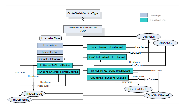
Figure 17 – ShelvedStateMachineType model......................................... 53
Figure 18 – LimitAlarmType................................................................. 60
Figure 19 – ExclusiveLimitStateMachineType.......................................... 63
Figure 20 – ExclusiveLimitAlarmType.................................................... 65
Figure 21 – NonExclusiveLimitAlarmType............................................... 66
Figure 22 – DiscreteAlarmType Hierarchy.............................................. 71
Figure 23 – ConditionClass type hierarchy.............................................. 74
Figure 24 – AuditEvent hierarchy.......................................................... 78
Figure 25 – Refresh Related Event Hierarchy.......................................... 82
Figure 26 – Typical HasNotifier Hierarchy.............................................. 85
Figure 27 – Use of HasCondition in a HasNotifier hierarchy....................... 86
Figure 28 – Use of HasCondition in an InstanceDeclaration....................... 86
Figure 29 – Use of HasCondition in a VariableType.................................. 87
Figure B.1 – Single state example........................................................ 98
Figure B.2 – Previous state example..................................................... 99
Figure B.3 – SuppressedState and OutOfServiceState example................ 100
Figure B.5 – HasCondition used with Condition instances........................ 103
Figure B.6 – HasCondition reference to a Condition type......................... 104
Figure B.7 – HasCondition used with an instance declaration................... 104
Figure D.1 – The type model of a wrapped COM AE server...................... 108
Figure D.2 – Mapping UA Event Types to COM A&E Event Types............. 112
Figure D.3 – Example mapping of UA Event Types to COM A&E categories 113
Figure F.1 – SystemState transitions................................................... 125
Figure F.2 – SystemStateStateMachineType Model................................ 126
Table 1 – Parameter types defined in 10000-3.......................................... 4
Table 2 – Parameter types defined in 10000-4.......................................... 4
Table 3 – TwoStateVariableType definition............................................. 14
Table 4 – ConditionVariableType definition............................................. 16
Table 5 – HasTrueSubState ReferenceType........................................... 17
Table 6 – HasFalseSubState ReferenceType.......................................... 18
Table 7 – HasAlarmSuppressionGroup ReferenceType............................. 18
Table 8 – AlarmGroupMember ReferenceType........................................ 18
Table 9 – AlarmSuppressionGroupMember ReferenceType....................... 19
Table 10 – ConditionType definition...................................................... 21
Table 11 – ConditionType Additional Subcomponents............................... 21
Table 12 – ConditionId SimpleAttributeOperand Illustration........................ 24
Table 13 – Disable result codes........................................................... 24
Table 14 – Disable Method AddressSpace definition................................ 25
Table 15 – Enable result codes............................................................ 25
Table 16 – Enable Method AddressSpace definition................................. 25
Table 17 – AddComment arguments...................................................... 26
Table 18 – AddComment result codes................................................... 26
Table 19 – AddComment Method AddressSpace definition........................ 26
Table 20 – ConditionRefresh parameters............................................... 27
Table 21 – ConditionRefresh result codes.............................................. 27
Table 22 – ConditionRefresh Method AddressSpace definition................... 28
Table 23 – ConditionRefresh2 parameters.............................................. 28
Table 24 – ConditionRefresh2 result codes............................................. 29
Table 25 – ConditionRefresh2 Method AddressSpace definition.................. 29
Table 26 – DialogConditionType definition.............................................. 30
Table 27 – DialogConditionType Additional Subcomponents...................... 30
Table 28 – Respond parameters........................................................... 31
Table 29 – Respond Result Codes........................................................ 31
Table 30 – Respond Method AddressSpace definition............................... 32
Table 31 – Respond2 parameters......................................................... 32
Table 32 – Respond2 Result Codes...................................................... 32
Table 33 – Respond2 Method AddressSpace definition............................. 32
Table 34 – AcknowledgeableConditionType definition............................... 33
Table 35 – AcknowledgeableConditionType Additional Subcomponents....... 33
Table 36 – Acknowledge parameters..................................................... 34
Table 37 – Acknowledge result codes.................................................... 34
Table 38 – Acknowledge Method AddressSpace definition......................... 35
Table 39 – Confirm Method parameters................................................. 35
Table 40 – Confirm result codes........................................................... 35
Table 41 – Confirm Method AddressSpace definition................................ 36
Table 42 – AlarmConditionType definition.............................................. 38
Table 43 – AlarmConditionType Additional Subcomponents....................... 39
Table 44 – AlarmGroupType definition................................................... 42
Table 45 – AlarmSuppressionGroupType definition.................................. 42
Table 46 – Reset result codes.............................................................. 43
Table 47 – Reset Method AddressSpace definition................................... 43
Table 48 – Reset2 Method parameters.................................................. 43
Table 49 – Reset2 result codes............................................................ 44
Table 50 – Reset2 Method AddressSpace definition................................. 44
Table 51 – Silence result codes............................................................ 44
Table 52 – Silence Method AddressSpace definition................................. 45
Table 53 – Suppress result codes......................................................... 45
Table 54 – Suppress Method AddressSpace definition.............................. 45
Table 55 – Suppress2 Method parameters............................................. 46
Table 56 – Suppress2 Method AddressSpace definition............................ 46
Table 57 – Unsuppress result codes...................................................... 47
Table 58 – Unsuppress Method AddressSpace definition........................... 47
Table 59 – Unsuppress2 Method parameters.......................................... 47
Table 60 – Unsuppress2 Method AddressSpace definition......................... 48
Table 61 – RemoveFromService result codes......................................... 48
Table 62 – RemoveFromService Method AddressSpace definition.............. 48
Table 63 – RemoveFromService2 Method parameters.............................. 49
Table 64 – RemoveFromService2 result codes........................................ 49
Table 65 – RemoveFromService2 Method AddressSpace definition............. 49
Table 66 – PlaceInService result codes................................................. 50
Table 67 – PlaceInService Method AddressSpace definition...................... 50
Table 68 – PlaceInService2 Method parameters...................................... 50
Table 69 – PlaceInService2 result codes................................................ 50
Table 70 – PlaceInService2 Method AddressSpace definition..................... 51
Table 71 – GetGroupMemberships result codes...................................... 51
Table 72 – GetGroupMemberships Method AddressSpace definition........... 51
Table 73 – ShelvedStateMachineType definition...................................... 53
Table 74 – ShelvedStateMachineType Additional References..................... 54
Table 76 – Unshelve result codes......................................................... 55
Table 77 – Unshelve Method AddressSpace definition.............................. 55
Table 78 – Unshelve2 Method parameters.............................................. 55
Table 79 – Unshelve2 result codes....................................................... 56
Table 80 – Unshelve2 Method AddressSpace definition............................ 56
Table 81 – TimedShelve parameters..................................................... 56
Table 82 – TimedShelve result codes.................................................... 56
Table 83 – TimedShelve Method AddressSpace definition......................... 57
Table 84 – TimedShelve2 parameters.................................................... 57
Table 85 – TimedShelve2 result codes.................................................. 57
Table 86 – TimedShelve2 Method AddressSpace definition....................... 58
Table 87 – OneShotShelve result codes................................................. 58
Table 88 – OneShotShelve Method AddressSpace definition...................... 58
Table 89 – OneShotShelve2 Method parameters..................................... 59
Table 90 – OneShotShelve2 result codes............................................... 59
Table 91 – OneShotShelve2 Method AddressSpace definition.................... 59
Table 92 – LimitAlarmType definition..................................................... 61
Table 93 – ExclusiveLimitStateMachineType definition............................. 63
Table 94 – ExclusiveLimitStateMachineType Additional References............ 64
Table 96 – ExclusiveLimitAlarmType definition........................................ 65
Table 97 – NonExclusiveLimitAlarmType definition................................... 66
Table 98 – NonExclusiveLimitAlarmType Additional Subcomponents........... 67
Table 99 – NonExclusiveLevelAlarmType definition.................................. 67
Table 100 – ExclusiveLevelAlarmType definition...................................... 68
Table 101 – NonExclusiveDeviationAlarmType definition........................... 68
Table 102 – ExclusiveDeviationAlarmType definition................................ 69
Table 103 – NonExclusiveRateOfChangeAlarmType definition................... 70
Table 104 – ExclusiveRateOfChangeAlarmType definition......................... 70
Table 105 – DiscreteAlarmType definition.............................................. 71
Table 106 – OffNormalAlarmType definition............................................ 71
Table 107 – SystemOffNormalAlarmType definition.................................. 72
Table 108 – TripAlarmType definition.................................................... 72
Table 109 – InstrumentDiagnosticAlarmType definition............................. 72
Table 110 – SystemDiagnosticAlarmType definition................................. 73
Table 111 – CertificateExpirationAlarmType definition.............................. 73
Table 112 – DiscrepancyAlarmType definition......................................... 73
Table 113 – BaseConditionClassType definition...................................... 75
Table 114 – ProcessConditionClassType definition.................................. 75
Table 115 – MaintenanceConditionClassType definition............................ 75
Table 116 – SystemConditionClassType definition................................... 76
Table 117 – SafetyConditionClassType definition..................................... 76
Table 118 – HighlyManagedAlarmConditionClassType definition................. 76
Table 119 – TrainingConditionClassType definition.................................. 77
Table 120 – StatisticalConditionClassType definition................................ 77
Table 121 – TestingConditionClassType definition................................... 77
Table 122 – AuditConditionEventType definition...................................... 78
Table 123 – AuditConditionEnableEventType definition............................. 79
Table 124 – AuditConditionCommentEventType definition......................... 79
Table 125 – AuditConditionRespondEventType definition.......................... 79
Table 126 – AuditConditionAcknowledgeEventType definition.................... 80
Table 127 – AuditConditionConfirmEventType definition............................ 80
Table 128 – AuditConditionShelvingEventType definition........................... 80
Table 129 – AuditConditionSuppressionEventType definition..................... 81
Table 130 – AuditConditionSilenceEventType definition............................ 81
Table 131 – AuditConditionResetEventType definition.............................. 81
Table 132 – AuditConditionOutOfServiceEventType definition.................... 81
Table 133 – RefreshStartEventType definition......................................... 82
Table 134 – RefreshEndEventType definition.......................................... 82
Table 135 – RefreshRequiredEventType definition................................... 83
Table 136 – HasCondition ReferenceType Definition................................ 83
Table 137 – Alarm & Condition result codes............................................ 84
Table 138 – HasEffectDisable ReferenceType......................................... 88
Table 139 – HasEffectEnable ReferenceType......................................... 89
Table 140 – HasEffectSuppressed ReferenceType................................... 89
Table 141 – HasEffectUnsuppressed ReferenceType............................... 90
Table 142 – AlarmStateVariableType definition....................................... 92
Table 143 – AlarmMask values............................................................. 92
Table 144 – AlarmMask definition......................................................... 92
Table 145 – AlarmMetricsType Definition............................................... 93
Table 146 – AlarmRateVariableType Definition........................................ 94
Table 147 – Suppress result codes....................................................... 94
Table 148 – Reset Method AddressSpace Definition................................. 94
Table A.1 – Recommended state names for LocaleId “en”......................... 95
Table A.2 – Recommended DisplayNames for LocaleId “en”...................... 95
Table A.3 – Recommended state names for LocaleId “de”......................... 96
Table A.4 – Recommended DisplayNames for LocaleId “de”...................... 96
Table A.5 – Recommended state names for LocaleId “fr”........................... 96
Table A.6 – Recommended DisplayNames for LocaleId “fr”........................ 96
Table A.7 – Recommended dialog response options................................. 97
Table B.1 – Example of a Condition that only keeps the latest state............ 98
Table B.3 – Example of a Condition that is Suppressed / OutOfService...... 101
Table C.1 – EEMUA Terms................................................................ 105
Table D.1 – Mapping from standard Event categories to OPC UA Event types 107
Table D.5 – Event category attribute mapping table................................ 113
Table F.1 – SystemStateStateMachineType definition............................. 127
Table F.2 – SystemStateStateMachineType additional references............. 128
____________
UNIFIED ARCHITECTURE –
This specification is the specification for developers of OPC UA applications. The specification is a result of an analysis and design process to develop a standard interface to facilitate the development of applications by multiple vendors that shall inter-operate seamlessly together.
Copyright © 2006-2023, OPC Foundation, Inc.
COPYRIGHT RESTRICTIONS
Any unauthorized use of this specification may violate copyright laws, trademark laws, and communications regulations and statutes. This document contains information which is protected by copyright. All Rights Reserved. No part of this work covered by copyright herein may be reproduced or used in any form or by any means--graphic, electronic, or mechanical, including photocopying, recording, taping, or information storage and retrieval systems--without permission of the copyright owner.
OPC Foundation members and non-members are prohibited from copying and redistributing this specification. All copies must be obtained on an individual basis, directly from the OPC Foundation Web site http://www.opcfoundation.org
PATENTS
The attention of adopters is directed to the possibility that compliance with or adoption of OPC specifications may require use of an invention covered by patent rights. OPC shall not be responsible for identifying patents for which a license may be required by any OPC specification, or for conducting legal inquiries into the legal validity or scope of those patents that are brought to its attention. OPC specifications are prospective and advisory only. Prospective users are responsible for protecting themselves against liability for infringement of patents.
WARRANTY AND LIABILITY DISCLAIMERS
WHILE THIS PUBLICATION IS BELIEVED TO BE ACCURATE, IT IS PROVIDED "AS IS" AND MAY CONTAIN ERRORS OR MISPRINTS. THE OPC FOUDATION MAKES NO WARRANTY OF ANY KIND, EXPRESSED OR IMPLIED, WITH REGARD TO THIS PUBLICATION, INCLUDING BUT NOT LIMITED TO ANY WARRANTY OF TITLE OR OWNERSHIP, IMPLIED WARRANTY OF MERCHANTABILITY OR WARRANTY OF FITNESS FOR A PARTICULAR PURPOSE OR USE. IN NO EVENT SHALL THE OPC FOUNDATION BE LIABLE FOR ERRORS CONTAINED HEREIN OR FOR DIRECT, INDIRECT, INCIDENTAL, SPECIAL, CONSEQUENTIAL, RELIANCE OR COVER DAMAGES, INCLUDING LOSS OF PROFITS, REVENUE, DATA OR USE, INCURRED BY ANY USER OR ANY THIRD PARTY IN CONNECTION WITH THE FURNISHING, PERFORMANCE, OR USE OF THIS MATERIAL, EVEN IF ADVISED OF THE POSSIBILITY OF SUCH DAMAGES.
The entire risk as to the quality and performance of software developed using this specification is borne by you.
RESTRICTED RIGHTS LEGEND
This Specification is provided with Restricted Rights. Use, duplication or disclosure by the U.S. government is subject to restrictions as set forth in (a) this Agreement pursuant to DFARs 227.7202-3(a); (b) subparagraph (c)(1)(i) of the Rights in Technical Data and Computer Software clause at DFARs 252.227-7013; or (c) the Commercial Computer Software Restricted Rights clause at FAR 52.227-19 subdivision (c)(1) and (2), as applicable. Contractor / manufacturer are the OPC Foundation, 16101 N. 82nd Street, Suite 3B, Scottsdale, AZ, 85260-1830.
COMPLIANCE
The OPC Foundation shall at all times be the sole entity that may authorize developers, suppliers and sellers of hardware and software to use certification marks, trademarks or other special designations to indicate compliance with these materials. Products developed using this specification may claim compliance or conformance with this specification if and only if the software satisfactorily meets the certification requirements set by the OPC Foundation. Products that do not meet these requirements may claim only that the product was based on this specification and must not claim compliance or conformance with this specification.
Trademarks
Most computer and software brand names have trademarks or registered trademarks. The individual trademarks have not been listed here.
GENERAL PROVISIONS
Should any provision of this Agreement be held to be void, invalid, unenforceable or illegal by a court, the validity and enforceability of the other provisions shall not be affected thereby.
This Agreement shall be governed by and construed under the laws of the State of Minnesota, excluding its choice or law rules.
This Agreement embodies the entire understanding between the parties with respect to, and supersedes any prior understanding or agreement (oral or written) relating to, this specification.
ISSUE REPORTING
The OPC Foundation strives to maintain the highest quality standards for its published specifications, hence they undergo constant review and refinement. Readers are encouraged to report any issues and view any existing errata here: http://www.opcfoundation.org/errata
Revision 1.05.03 Highlights
The following table includes the Mantis issues resolved with this revision.
|
Mantis ID |
Scope |
Summary |
Resolution |
|
Errata |
For the AcknowledgeableConditionType the text in an error description references ConditionType |
Change ConditionType to AcknowledgeableConditionTypeA |
|
|
Errata |
ConditionId needs further clarification |
Added text to explain that ConditionId have to remain constant |
OPC Unified Architecture
Part 9: Alarms and Conditions Specification
This document specifies the representation of Alarms and Conditions in the OPC Unified Architecture. Included is the Information Model representation of Alarms and Conditions in the OPC UA address space. Other aspects of alarm systems like alarm philosophy, life cycle, alarm response times, alarm types and many other details are captured in standards such as IEC 62682 and ISA 18.2. The Alarms and Conditions Information Model in this specification, is designed in accordance with IEC 62682 and ISA 18.2. Annex C specifies how the model described in this document maps to EEMUA. Annex D specifies a recommended mapping between OPC Classic Alarm & Events (A&E) servers to the model described in this document.
The following documents, in whole or in part, are normatively referenced in this document and are indispensable for its application.
10000-1: OPC UA Specification: Part 1 – Concepts
https://www.opcfoundation.org/UA/Part1/
10000-3: OPC UA Specification: Part 3 – Address Space Model
https://www.opcfoundation.org/UA/Part3/
10000-4: OPC UA Specification: Part 4 – Services
https://www.opcfoundation.org/UA/Part4/
10000-5: OPC UA Specification: Part 5 – Information Model
https://www.opcfoundation.org/UA/Part5/
10000-6: OPC UA Specification: Part 6 – Mappings
https://www.opcfoundation.org/UA/Part6/
10000-7: OPC UA Specification: Part 7 – Profiles
https://www.opcfoundation.org/UA/Part7/
10000-8: OPC UA Specification: Part 8 – Data Access
https://www.opcfoundation.org/UA/Part8/
10000-11: OPC UA Specification: Part 11 – Historical Access
https://www.opcfoundation.org/UA/Part11/
10000-16: OPC UA Specification: Part 16 – State Machines
https://www.opcfoundation.org/UA/Part16/
EEMUA: 2nd Edition EEMUA 191 – Alarm System – A guide to design, management and procurement (Appendixes 6, 7, 8, 9)
https://www.eemua.org/Products/Publications/Print/EEMUA-Publication-191.aspx
IEC 62682: Management of alarm systems for the process industries (Edition 1.0 2014-10)
https://webstore.iec.ch/publication/7363
ISA 18.2: Management of Alarm Systems for the Process Industries
https://webstore.ansi.org/Standards/ISA/ansiisa182016
IETF RFC 2045: Multipurpose Internet Mail Extensions (MIME) Part One
https://www.ietf.org/rfc/rfc2045.txt
IETF RFC 2046: Multipurpose Internet Mail Extensions (MIME) Part Two
https://www.ietf.org/rfc/rfc2046.txt
IETF RFC 2047: Multipurpose Internet Mail Extensions (MIME) Part Three
https://www.ietf.org/rfc/rfc2047.txt
For the purposes of this document, the terms and definitions given in 10000-1, 10000-3, 10000-4, and 10000-5 as well as the following apply.
Acknowledge
Operator action that indicates recognition of an Alarm
Note 1 to entry: This definition is copied from EEMUA. The term “Accept” is another common term used to describe Acknowledge. They can be used interchangeably. This document will use Acknowledge.
Active
state for an Alarm that indicates that the situation the Alarm is representing currently exists
Note 1 to entry: Other common terms defined by EEMUA are “Standing” for an Active Alarm and “Cleared” when the Condition has returned to normal and is no longer Active.
3.1.3
AdaptiveAlarm
Alarm for which the set point or limits are changed by an algorithm.
Note 1 to entry: AdaptiveAlarms are alarms that are adjusted automatically by algorithms. These algorithms might detect conditions in a plant and change setpoints or limits to keep alarms from occurring. These changes occur, in many cases, without Operator interactions.
3.1.4
AlarmFlood
condition during which the alarm rate is greater than the Operator can effectively manage
Note 1 to entry: OPC UA does not define the conditions that would be considered alarm flooding, these conditions are defined in other specification such as IEC 62682 or ISA 18.2
3.1.5
AlarmManager
application that manages alarms in a system
Note 1 An AlarmManager usually includes higher level functionality like intelligent alarm suppression or dynamic adjustment of limits or other alarm management functionality. It will still act on the alarm model associated with the actual alarm source.
3.1.6
AlarmSuppressionGroup
group of Alarms that is used to suppress other Alarms.
Note 1 to entry: An AlarmSuppressionGroup is an instance of an AlarmGroupType that is used to suppress other Alarms. If any Alarm in the group is active, then the AlarmSuppressionGroup is active. If all Alarms in the AlarmSuppressionGroup are inactive then the AlarmSuppressionGroup is inactive.
Note 2 to entry: The Alarm to be affected references AlarmSuppressionGroups with a HasAlarmSuppressionGroup ReferenceType.
3.1.7
ConditionClass
Condition grouping that indicates in which domain or for what purpose a certain Condition is used
Note 1 to entry: Some top-level ConditionClasses are defined in this specification. Vendors or organisations may derive more concrete classes or define different top-level classes.
3.1.8
ConditionBranch
specific state of a Condition
Note 1 to entry: The Server can maintain ConditionBranches for the current state as well as for previous states.
ConditionSource
element which a specific Condition is based upon or related to
Note 1 to entry: Typically, it will be a Variable representing a process tag (e.g. FIC101) or an Object representing a device or subsystem.
In Events generated for Conditions, the SourceNode Property (inherited from the BaseEventType) will contain the NodeId of the ConditionSource.
Confirm
Operator action informing the Server that a corrective action has been taken to address the cause of the Alarm
3.1.11
Disable
system is configured such that the Alarm will not be generated even though the base Alarm Condition is present
Note 1 to entry: This definition is copied from EEMUA and is further defined in EEMUA.
In IEC 62682 disable has been replaced with “Out of Service”.
3.1.12
LatchingAlarm
alarm that remains in alarm state after the process condition has returned to normal and requires an Operator reset before the alarm returns to normal
Note 1 to entry: Latching alarms are typically discrepancy alarms, where an action does not occur within a specific time. Once the action occurs the alarm stays active until it is reset.
3.1.13
Operator
special user who is assigned to monitor and control a portion of a process
Note 1 to entry: “A Member of the operations team who is assigned to monitor and control a portion of the process and is working at the control system’s Console” as defined in EEMUA. In this standard an Operator is a special user. All descriptions that apply to general users also apply to Operators.
3.1.14
Refresh
act of providing an update to an Event Subscription that provides all Alarms which are considered to be Retained
Note 1 to entry: This concept is further defined in EEMUA.
3.1.15
Retain
Alarm in a state that is interesting for a Client wishing to synchronize its state of Conditions with the Server’s state
3.1.16
Shelving
facility where the Operator is able to temporarily prevent an Alarm from being displayed to the Operator when it is causing the Operator a nuisance
Note 1 to entry ”A Shelved Alarm will be removed from the list and will not re-annunciate until un-shelved.” as defined in EEMUA.
3.1.17
Suppress
act of determining whether an Alarm should not occur
Note 1 to entry: “An Alarm is suppressed when logical criteria are applied to determine that the Alarm should not occur, even though the base Alarm Condition (e.g. Alarm setting exceeded) is present” as defined in EEMUA. In IEC 62682 Suppressed Alarms are also described as being “Suppressed by Design”, in that the system is designed with logic to Suppress an Alarm when certain criteria exist. For example, if a process unit is taken off line then low level alarms are Suppressed for all equipment in the off-line unit.
A&E Alarm & Event (as used for OPC COM)
COM (Microsoft Windows) Component Object Model
DA Data Access
MIME Multipurpose Internet Mail Extensions
The following tables describe the data types that are used throughout this document. These types are separated into two tables. Base data types defined in 10000-3 are given in Table 1. The base types and data types defined in 10000-4 are given in Table 2.
Table 1 – Parameter types defined in 10000-3
|
Parameter Type |
|
Argument |
|
NodeId |
|
LocalizedText |
|
Boolean |
|
ByteString |
|
Double |
|
Duration |
|
String |
|
UInt16 |
|
Int32 |
|
UtcTime |
Table 2 – Parameter types defined in 10000-4
|
Parameter Type |
|
IntegerId |
|
StatusCode |
This standard defines an Information Model for Conditions, Dialog Conditions, and Alarms including acknowledgement capabilities. It is built upon and extends base Event handling which is defined in 10000-3, 10000-4 and 10000-5. This Information Model can also be extended to support the additional needs of specific domains. The details of what aspects of the Information Model are supported are defined via Profiles (see 10000-7 for Profile definitions). Some systems may expose historical Events and Conditions via the standard Historical Access framework (see 10000-11 for Historical Event definitions).
Conditions are used to represent the state of a system or one of its components. Some common examples are:
· a temperature exceeding a configured limit
· a device needing maintenance
· a batch process that requires a user to confirm some step in the process before proceeding
Each Condition instance is of a specific ConditionType. The ConditionType and derived types are sub-types of the BaseEventType (see 10000-3 and 10000-5). This part defines types that are common across many industries. It is expected that vendors or other standardisation groups will define additional ConditionTypes deriving from the common base types defined in this part. The ConditionTypes supported by a Server are exposed in the AddressSpace of the Server.
Condition instances are specific implementations of a ConditionType. It is up to the Server whether such instances are also exposed in the Server’s AddressSpace. Clause 4.10 provides additional background about Condition instances. Condition instances shall have a unique identifier to differentiate them from other instances. This is independent of whether they are exposed in the AddressSpace.
As mentioned above, Conditions represent the state of a system or one of its components. In certain cases, however, previous states that still need attention also have to be maintained. ConditionBranches are introduced to deal with this requirement and distinguish current state and previous states. Each ConditionBranch has a BranchId that differentiates it from other branches of the same Condition instance. The ConditionBranch which represents the current state of the Condition (the trunk) has a NULL BranchId. Servers can generate separate Event Notifications for each branch. When the state represented by a ConditionBranch does not need further attention, a final Event Notification for this branch will have the Retain Property set to False. Clause 5.5 provides more information and use cases. Maintaining previous states and therefore the support of multiple branches is optional for Servers.
Conceptually, the lifetime of the Condition instance is independent of its state. However, Servers may provide access to Condition instances only while ConditionBranches exist.
The base Condition state model is illustrated in Figure 1. It is extended by the various Condition subtypes defined in this standard and may be further extended by vendors or other standardisation groups. The primary states of a Condition are disabled and enabled. The Disabled state is intended to allow Conditions to be turned off at the Server or below the Server (in a device or some underlying system). The Enabled state is normally extended with the addition of sub-states.
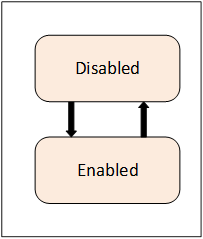
Figure 1 – Base Condition state model
A transition into the Disabled state results in a Condition Event however no subsequent Event Notifications are generated until the Condition returns to the Enabled state.
ISA 18.2 and IEC 62682, which are the basis for this information model, no longer support enabling and disabling of alarms. As a result, even though this feature is still supported for backward compatibility it is recommended that alarms never be disabled.
When a Condition enters the Enabled state, that transition and all subsequent transitions result in Condition Events being generated by the Server.
If Auditing is supported by a Server, the following Auditing related action shall be performed. The Server will generate AuditEvents for Enable and Disable operations (either through a Method call or some Server / vendor – specific means), rather than generating an AuditEvent Notification for each Condition instance being enabled or disabled. For more information, see the definition of AuditConditionEnableEventType in 5.10.2. AuditEvents are also generated for any other Operator action that results in changes to the Conditions.
AcknowledgeableConditions are sub-types of the base ConditionType. AcknowledgeableConditions expose states to indicate whether a Condition has to be acknowledged or confirmed.
An AckedState and a ConfirmedState extend the EnabledState defined by the Condition. The state model is illustrated in Figure 2. The enabled state is extended by adding the AckedState and (optionally) the ConfirmedState.
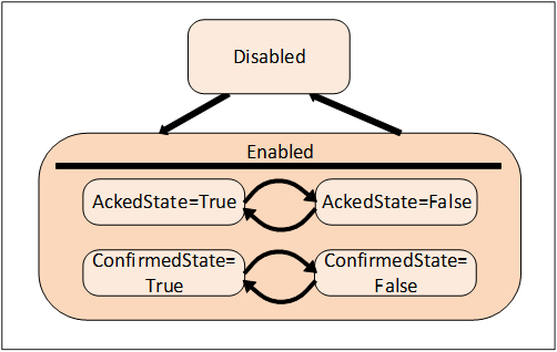
Figure 2 – AcknowledgeableConditions state model
Acknowledgment of the transition may come from the Client or may be due to some logic internal to the Server. For example, acknowledgment of a related Condition may result in this Condition becoming acknowledged, or the Condition may be set up to automatically Acknowledge itself when the acknowledgeable situation disappears.
Two Acknowledge state models are supported by this standard. Either of these state models can be extended to support more complex acknowledgement situations.
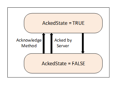
The basic Acknowledge state model is illustrated in Figure 3. This model defines an AckedState. The specific state changes that result in a change to the state depend on a Server’s implementation. For example, in typical Alarm models the change is limited to a transition to the Active state or transitions within the Active state. More complex models however can also allow for changes to the AckedState when the Condition transitions to an inactive state.
Figure 3 - Acknowledge State Model
A more complex state model which adds a confirmation to the basic Acknowledge is illustrated in Figure 4. The Confirmed Acknowledge model is typically used to differentiate between acknowledging the presence of a Condition and having done something to address the Condition. For example, an Operator receiving a motor high temperature Notification calls the Acknowledge Method to inform the Server that the high temperature has been observed. The Operator then takes some action such as lowering the load on the motor in order to reduce the temperature. The Operator then calls the Confirm Method to inform the Server that a corrective action has been taken.
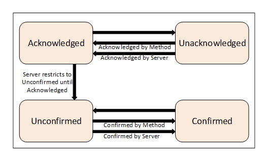
Figure 4 - Confirm acknowledge State model
The AcknowledgeableConditions model can also be used for a simple Condition that requires a confirmation. For example, a motor start event might need to be acknowledged by an operator, this event is not an alarm, just an action that needs to be acknowledged by the operator. It could also be an event that is generated for an operator change of a process input (grade of paper being made) that needs to be acknowledged. It is not something that requires an anwser like a question, for this there are DialogCondition. It is just an acknowledge that the operator observed the change.
Some systems require that previous states of a Condition are preserved for some time. A common use case is the acknowledgement process. In certain environments, it is required to acknowledge both the transition into Active state and the transition into an inactive state. Systems with strict safety rules sometimes require that every transition into Active state has to be acknowledged. In situations where state changes occur in short succession there can be multiple unacknowledged states and the Server maintains ConditionBranches for all previous unacknowledged states. These branches will be deleted after they have been acknowledged or if they reached their final state.
Multiple ConditionBranches can also be used for other use cases where snapshots of previous states of a Condition require additional actions.
When a Client subscribes for Events, the Notification of transitions will begin at the time of the Subscription. The currently existing state will not be reported. This means for example that Clients are not informed of currently Active Alarms until a new state change occurs.
Clients can obtain the current state of all Condition instances that are in an interesting state, by requesting a Refresh for a Subscription. It should be noted that Refresh is not a general replay capability since the Server is not required to maintain an Event history.
Clients request a Refresh by calling the ConditionRefresh Method. The Server will respond with a RefreshStartEventType Event. This Event is followed by the Retained Conditions. The Server may also send new Event Notifications interspersed with the Refresh related Event Notifications. After the Server is done with the Refresh, a RefreshEndEvent is issued marking the completion of the Refresh. Clients shall check for multiple Event Notifications for a ConditionBranch to avoid overwriting a new state delivered together with an older state from the Refresh process. If a ConditionBranch exists, then the current Condition shall be reported. This is True even if the only interesting item regarding the Condition is that ConditionBranches exist. This allows a Client to accurately represent the current Condition state.
A Client that wishes to display the current status of Alarms and Conditions (known as a “current Alarm display”) would use the following logic to process Refresh Event Notifications. The Client flags all Retained Conditions as suspect on reception of the Event of the RefreshStartEventType. The Client adds any new Events that are received during the Refresh without flagging them as suspect. The Client also removes the suspect flag from any Retained Conditions that are returned as part of the Refresh. When the Client receives a RefreshEndEvent, the Client removes any remaining suspect Events, since they no longer apply.
The following items should be noted with regard to ConditionRefresh:
· As described in 4.4 some systems require that previous states of a Condition are preserved for some time. Some Servers – in particular if they require acknowledgement of previous states – will maintain separate ConditionBranches for prior states that still need attention.
ConditionRefresh shall issue Event Notifications for all interesting states (current and previous) of a Condition instance and Clients can therefore receive more than one Event for a Condition instance with different BranchIds.
· Under some circumstances a Server may not be capable of ensuring the Client is fully in sync with the current state of Condition instances. For example, if the underlying system represented by the Server is reset or communications are lost for some period of time the Server may need to resynchronize itself with the underlying system. In these cases, the Server shall send an Event of the RefreshRequiredEventType to advise the Client that a Refresh may be necessary. A Client receiving this special Event should initiate a ConditionRefresh as noted in this clause.
· To ensure a Client is always informed, the three special EventTypes (RefreshEndEventType, RefreshStartEventType and RefreshRequiredEventType) ignore the Event content filtering associated with a Subscription and will always be delivered to the Client.
· ConditionRefresh applies to a Subscription. If multiple Event Notifiers are included in the same Subscription, all Event Notifiers are refreshed.
Comment, severity and quality are important elements of Conditions and any change to them will cause Event Notifications.
The Severity of a Condition is inherited from the base Event model defined in 10000-5. It indicates the urgency of the Condition and is also commonly called ‘priority’, especially in relation to Alarms in the ProcessConditionClassType.
A Comment is a user generated string that is to be associated with a certain state of a Condition.
Quality refers to the quality of the data value(s) upon which this Condition is based. Since a Condition is usually based on one or more Variables, the Condition inherits the quality of these Variables. E.g., if the process value is “Uncertain”, the “Level Alarm” Condition is also questionable. If more than one variable is represented by a given condition or if the condition is from an underlining system and no direct mapping to a variable is available, it is up to the application to determine what quality is displayed as part of the condition.
Dialogs are ConditionTypes used by a Server to request user input. They are typically used when a Server has entered some state that requires intervention by a Client. For example, a Server monitoring a paper machine indicates that a roll of paper has been wound and is ready for inspection. The Server would activate a Dialog Condition indicating to the user that an inspection is required. Once the inspection has taken place the user responds by informing the Server of an accepted or unaccepted inspection allowing the process to continue.
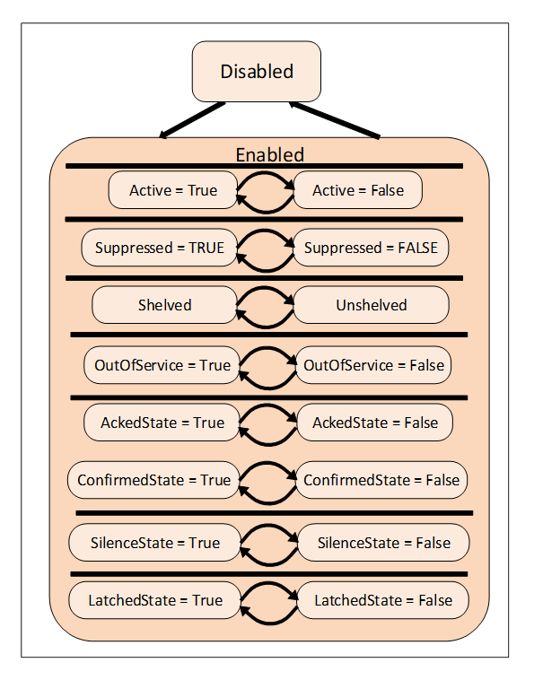
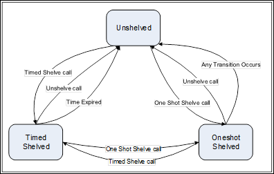
Alarms are specializations of AcknowledgeableConditions that add the concepts of an Active state and other states like Shelving state and Suppressed state to a Condition. The state model is illustrated in Figure 5. The complete model with all states is defined in 5.8.
Figure 5 – Alarm state machine model
An Alarm in the Active state indicates that the situation the Condition is representing currently exists. When an Alarm is an inactive state it is representing a situation that has returned to a normal state.
Some Alarm subtypes introduce sub-states of the Active state. For example, an Alarm representing a temperature may provide a high level state as well as a critically high state (see following Clause).
The shelving state can be set by an Operator via OPC UA Methods. The suppressed state is set internally by the Server due to system specific reasons. Alarm systems typically implement the suppress, out of service and shelve features to help keep Operators from being overwhelmed during Alarm “storms” by limiting the number of Alarms an Operator sees on a current Alarm display. This is accomplished by setting the SuppressedOrShelved flag on second order dependent Alarms and/or Alarms of less severity, leading the Operator to concentrate on the most critical issues.
The LatchedState is a state that is added to any alarm that requires additional processing, once it goes active it does not clear until it is explicitly reset, even if the value that triggered the alarm returns to normal. This might be an alarm that requires a physical inspection once it has occurred to ensure it is no longer in alarm, or a series of tests that might be required to ensure the alarm is no longer active or some other actions. Any AlarmType can become a latched alarm by the addition of this optional sub-state.
The shelved, out of service and suppressed states differ from the Disabled state in that Alarms are still fully functional and can be included in Subscription Notifications to a Client. A disabled Alarm is not processed in any manner, and is not supported as part of the active Alarm model defined in ISA 18.2.
Alarms follow a typical timeline that is illustrated in Figure 6. They have a number of delay times associated with them and a number of states that they might occupy. The goal of an alarming system is to inform Operators about conditions in a timely manner and allow the Operator to take some action before some consequences occur. The consequences may be economic (product is not usable and must be discard), may be physical (tank overflows), may safety (fire or explosion could occur) or any of a number of other possibilities. Typically, if no action is taken related to an alarm for some period of time the process will cross some threshold at which point consequences will start to occur. The OPC UA Alarm model describes these states, delays and actions.
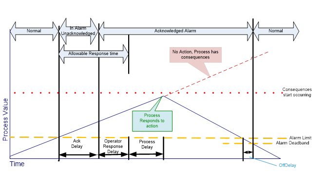
Figure 6 – Typical Alarm Timeline example
In some cases, it is desirable to further define the Active state of an Alarm by providing a sub-state machine for the Active State. For example, a multi-state level Alarm when in the Active state may be in one of the following sub-states: LowLow, Low, High or HighHigh. The state model is illustrated in Figure 7.
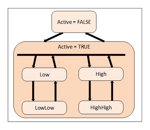
Figure 7 – Multiple active states example
With the multi-state Alarm model, state transitions among the sub-states of Active are allowed without causing a transition out of the Active state.
To accommodate different use cases both a (mutually) exclusive and a non-exclusive model are supported.
Exclusive means that the Alarm can only be in one sub-state at a time. If for example a temperature exceeds the HighHigh limit the associated exclusive level Alarm will be in the HighHigh sub-state and not in the High sub-state.
Some Alarm systems, however, allow multiple sub-states to exist in parallel. This is called non-exclusive. In the previous example where the temperature exceeds the HighHigh limit a non-exclusive level Alarm will be both in the High and the HighHigh sub-state.
Because Conditions always have a state (Enabled or Disabled) and possibly many sub-states it makes sense to have instances of Conditions present in the AddressSpace. If the Server exposes Condition instances they usually will appear in the AddressSpace as components of the Objects that “own” them. For example, a temperature transmitter that has a built-in high temperature Alarm would appear in the AddressSpace as an instance of some temperature transmitter Object with a HasComponent Reference to an instance of a LimitAlarmType.
The availability of instances allows Data Access Clients to monitor the current Condition state by subscribing to the Attribute values of Variable Nodes. The values of the nodes may not always correspond with the value that appear in Events, they may be more recent than what was in the Event.
While exposing Condition instances in the AddressSpace is not always possible, doing so allows for direct interaction (read, write and Method invocation) with a specific Condition instance. For example, if a Condition instance is not exposed, there is no way to invoke the Enable or Disable Method for the specific Condition instance.
The OPC UA Standards include provisions for auditing. Auditing is an important security and tracking concept. Audit records provide the “Who”, “When” and “What” information regarding user interactions with a system. These audit records are especially important when Alarm management is considered. Alarms are the typical instrument for providing information to a user that something needs the user’s attention. A record of how the user reacts to this information is required in many cases. Audit records are generated for all Method calls that affect the state of the system, for example, an Acknowledge Method call would generate an AuditConditionAcknowledgeEventType Event.
The standard AuditEventTypes defined in 10000-5 already include the fields required for Condition related audit records. To allow for filtering and grouping, this standard defines a number of sub-types of the AuditEventTypes but without adding new fields to them.
This standard describes the AuditEventType that each Method shall generate if Audit Events are supported by the Server. For example, the Disable Method has an AlwaysGeneratesEvent Reference to an AuditConditionEnableEventType. An Event of this type shall be generated for every invocation of the Method if audit events are supported. The audit Event describes the user interaction with the system, in some cases this interaction may affect more than one Condition or be related to more than one state.
In a system, alarms might be managed at different levels and by different applications. An alarm might be detected in an instrument, but the full alarm model for that alarm instance might be maintained in a higher level Server. This can cause issues in cases where the instrument is restarted or the UA Server that is acting as an alarm server is restarted. It is desirable that the state of alarms is maintained and that after any restart of either application all alarms recover their same state as before the restart. But it is acceptable if an alarm might require some management actions again following a restart. It is not acceptable that a device that is in alarm is no longer reported as being in alarm. For example, if the AlarmManager is restarted when it recovers it is able to detect that the device has an alarm, but it might not be able to recover that the alarm has a comment that had been entered as part of an alarm acknowledgement or even that is was acknowledged. The details of what states are expected to be recovered are provided in the individual object models.
The Alarm and Condition model extends the OPC UA base Event model by defining various Event Types based on the BaseEventType. All of the Event Types defined in this standard can be further extended to form domain or Server specific Alarm and Condition Types.
Instances of Alarm and Condition Types may be optionally exposed in the AddressSpace in order to allow direct access to the state of an Alarm or Condition. Instances not exposed in the AddressSpace still have a ConditionId (NodeId). This NodeId can be the target of references in the AddressSpace even though the target node does not exist in the AddressSpace. For example, an AlarmGroup might reference a number of Conditions that do not exist in the AddressSpace.
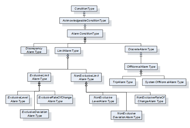
The following sub clauses define the OPC UA Alarm and Condition Types. Figure 8 informally describes the hierarchy of these Types. Subtypes of the LimitAlarmType and the DiscreteAlarmType are not shown.
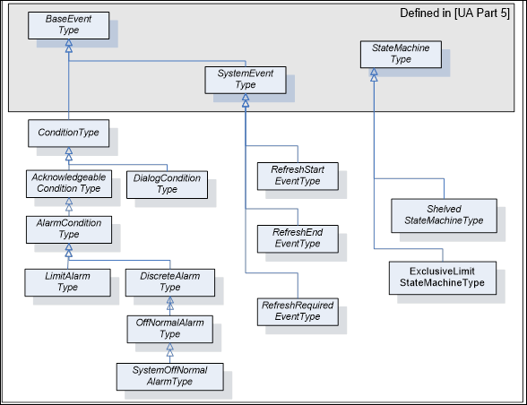
Figure 8 – ConditionType hierarchy
Most states defined in this standard are simple – i.e. they are either True or False. The TwoStateVariableType is introduced specifically for this use case. More complex states are modelled by using a StateMachineType defined in 10000-16.
The TwoStateVariableType is derived from the StateVariableType defined in 10000-16. and formally defined in Table 3.
Table 3 – TwoStateVariableType definition
|
Attribute |
Value |
||||
|
BrowseName |
TwoStateVariableType |
||||
|
DataType |
LocalizedText |
||||
|
ValueRank |
|||||
|
IsAbstract |
False |
||||
|
References |
NodeClass |
BrowseName |
DataType |
TypeDefinition |
Modelling |
|
Subtype of the StateVariableType defined in 10000-16. Note that a Reference to this subtype is not shown in the definition of the StateVariableType |
|||||
|
HasProperty |
Variable |
Id |
Boolean |
PropertyType |
Mandatory |
|
HasProperty |
Variable |
TransitionTime |
UtcTime |
PropertyType |
Optional |
|
HasProperty |
Variable |
EffectiveTransitionTime |
UtcTime |
PropertyType |
Optional |
|
HasProperty |
Variable |
TrueState |
LocalizedText |
PropertyType |
Optional |
|
HasProperty |
Variable |
FalseState |
LocalizedText |
PropertyType |
Optional |
|
|
|
|
|
|
|
|
ConformanceUnits |
|||||
|
A & C Basic |
|||||
The Value Attribute of an instance of TwoStateVariableType contains the current state as a human readable name. The EnabledState for example, might contain the name “Enabled” when True and “Disabled” when False.
Id is inherited from the StateVariableType and overridden to reflect the required DataType (Boolean). The value shall be the current state, i.e. either True or False.
TransitionTime specifies the time when the current state was entered.
EffectiveTransitionTime specifies the time when the current state or one of its sub states was entered. If, for example, a LevelAlarm is active and – while active – switches several times between High and HighHigh, then the TransitionTime stays at the point in time where the Alarm became active whereas the EffectiveTransitionTime changes with each shift of a sub state.
The optional Property EffectiveDisplayName from the StateVariableType is used if a state has sub states. It contains a human readable name for the current state after taking the state of any SubStateMachines in account. As an example, the EffectiveDisplayName of the EnabledState could contain “Active/HighHigh” to specify that the Condition is active and has exceeded the HighHigh limit.
Other optional Properties of the StateVariableType have no defined meaning for TwoStateVariableType.
TrueState and FalseState contain the localized string for the TwoStateVariableType value when its Id Property has the value True or False, respectively. Since the two Properties provide meta-data for the Type, Servers shall not allow these Properties to be selected in the Event filter for a MonitoredItem. The TrueState Property and FalseState Property shall only exist on InstanceDeclarations. See Figure 9 for an illustration. Clients can use the Read Service to get the values of the TrueState and FalseState Property.
A HasTrueSubState Reference is used to indicate that the True state has sub states.
A HasFalseSubState Reference is used to indicate that the False state has sub states.
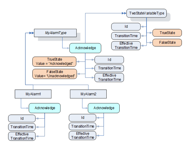
Figure 9 - TwoStateVariable Illustration
Various information elements of a Condition are not considered to be states. However, a change in their value is considered important and supposed to trigger an Event Notification. These information elements are called ConditionVariable.
ConditionVariables are represented by a ConditionVariableType, formally defined in Table 4.
Table 4 – ConditionVariableType definition
|
Attribute |
Value |
||||
|
BrowseName |
ConditionVariableType |
||||
|
DataType |
BaseDataType |
||||
|
ValueRank |
-2 (-2 = Any) |
||||
|
IsAbstract |
False |
||||
|
References |
NodeClass |
BrowseName |
DataType |
TypeDefinition |
Modelling |
|
Subtype of the BaseDataVariableType defined in 10000-5. |
|||||
|
HasProperty |
Variable |
SourceTimestamp |
UtcTime |
PropertyType |
Mandatory |
|
ConformanceUnits |
|||||
|
A & C Basic |
|||||
SourceTimestamp indicates the time of the last change of the Value of this ConditionVariable. It shall be the same time that would be returned from the Read Service inside the DataValue structure for the ConditionVariable Value Attribute.
This Clause defines ReferenceTypes that are needed beyond those already specified as part of 10000-3 and 10000-5. This includes extending TwoStateVariableType state machines with sub states and the addition of Alarm grouping.
The TwoStateVariableType References will only exist when sub states are available. For example, if a TwoStateVariableType machine is in a False State, then any sub states referenced from the True state will not be available. If an Event is generated while in the False state and information from the True state sub state is part of the data that is to be reported than this data would be reported as a NULL. With this approach, TwoStateVariableTypes can be extended with subordinate state machines in a similar fashion to the StateMachineType defined in 10000-16.
The HasTrueSubState ReferenceType is a concrete ReferenceType that can be used directly. It is a subtype of the NonHierarchicalReferences ReferenceType.
The semantics indicate that the sub state (the target Node) is a subordinate state of the True super state. If more than one state within a Condition is a sub state of the same super state (i.e. several HasTrueSubState References exist for the same super state) they are all treated as independent sub states. The representation in the AddressSpace is specified in Table 5.
The SourceNode of the Reference shall be an instance of a TwoStateVariableType and the TargetNode shall be either an instance of a TwoStateVariableType or an instance of a subtype of a StateMachineType.
It is not required to provide the HasTrueSubState Reference from super state to sub state, but it is required that the sub state provides the inverse Reference (IsTrueSubStateOf) to its super state.
Table 5 – HasTrueSubState ReferenceType
|
Attributes |
Value |
||
|
BrowseName |
HasTrueSubState |
||
|
InverseName |
IsTrueSubStateOf |
||
|
Symmetric |
False |
||
|
IsAbstract |
False |
||
|
References |
NodeClass |
BrowseName |
Comment |
|
|
|
|
|
|
ConformanceUnits |
|||
|
A & C Basic |
|||
The HasFalseSubState ReferenceType is a concrete ReferenceType that can be used directly. It is a subtype of the NonHierarchicalReferences ReferenceType.
The semantics indicate that the sub state (the target Node) is a subordinate state of the False super state. If more than one state within a Condition is a sub state of the same super state (i.e. several HasFalseSubState References exist for the same super state) they are all treated as independent sub states. The representation in the AddressSpace is specified in Table 6.
The SourceNode of the Reference shall be an instance of a TwoStateVariableType and the TargetNode shall be either an instance of a TwoStateVariableType or an instance of a subtype of a StateMachineType.
It is not required to provide the HasFalseSubState Reference from super state to sub state, but it is required that the sub state provides the inverse Reference (IsFalseSubStateOf) to its super state.
Table 6 – HasFalseSubState ReferenceType
|
Attributes |
Value |
||
|
BrowseName |
HasFalseSubState |
||
|
InverseName |
IsFalseSubStateOf |
||
|
Symmetric |
False |
||
|
IsAbstract |
False |
||
|
References |
NodeClass |
BrowseName |
Comment |
|
|
|
|
|
|
ConformanceUnits |
|||
|
A & C Basic |
|||
The HasAlarmSuppressionGroup ReferenceType is a concrete ReferenceType that can be used directly. It is a subtype of the HasComponent ReferenceType. The representation in the AddressSpace is specified in Table 7
This ReferenceType binds an AlarmSuppressionGroup to an Alarm.
The SourceNode of the Reference shall be an instance of an AlarmConditionType or sub type. The TargetNode shall be an instance of an AlarmGroupType.
Table 7 – HasAlarmSuppressionGroup ReferenceType
|
Attributes |
Value |
||
|
BrowseName |
HasAlarmSuppressionGroup |
||
|
InverseName |
IsAlarmSuppressionGroupOf |
||
|
Symmetric |
False |
||
|
IsAbstract |
False |
||
|
References |
NodeClass |
BrowseName |
Comment |
|
|
|
|
|
|
ConformanceUnits |
|||
|
A & C Suppression Group |
|||
The AlarmGroupMember ReferenceType is a concrete ReferenceType that can be used directly. It is a subtype of the Organizes Reference Type.
This ReferenceType is used to indicate the Alarm instances that are part of an Alarm Group. The representation in the AddressSpace is specified in Table 8
The SourceNode of the Reference shall be an instance of an AlarmGroupType or sub type of it. The TargetNode shall be an instance of an AlarmConditionType or a subtype of it.
Table 8 – AlarmGroupMember ReferenceType
|
Attributes |
Value |
|||
|
BrowseName |
AlarmGroupMember |
|||
|
InverseName |
MemberOfAlarmGroup |
|||
|
Symmetric |
False |
|||
|
IsAbstract |
False |
|||
|
References |
NodeClass |
BrowseName |
Comment |
|
|
|
|
|
|
|
|
ConformanceUnits |
||||
|
||||
|
A & C First in Group Alarm |
||||
The AlarmSuppressionGroupMember ReferenceType is a concrete ReferenceType that can be used directly. It is a subtype of the AlarmGroupMember ReferenceType.
This ReferenceType is used to indicate the Alarm instances or Boolean Variables that are part of an Alarm Group. The representation in the AddressSpace is specified in Table 9
The SourceNode of the Reference shall be an instance of an AlarmGroupType or sub type of it. The TargetNode shall be an instance of an AlarmConditionType or a subtype of it, or an instance of BaseDataVariableType that has a DataType of Boolean.
Table 9 – AlarmSuppressionGroupMember ReferenceType
|
Attributes |
Value |
|||
|
BrowseName |
AlarmSuppressionGroupMember |
|||
|
InverseName |
MemberOfAlarmSuppressionGroup |
|||
|
Symmetric |
False |
|||
|
IsAbstract |
False |
|||
|
References |
NodeClass |
BrowseName |
Comment |
|
|
|
|
|
|
|
|
ConformanceUnits |
||||
|
||||
|
|
||||
The Condition model extends the Event model by defining the ConditionType. The ConditionType introduces the concept of states differentiating it from the base Event model. Unlike the BaseEventType, Conditions are not transient. The ConditionType is further extended into Dialog and AcknowledgeableConditionType, each of which has their own sub-types.
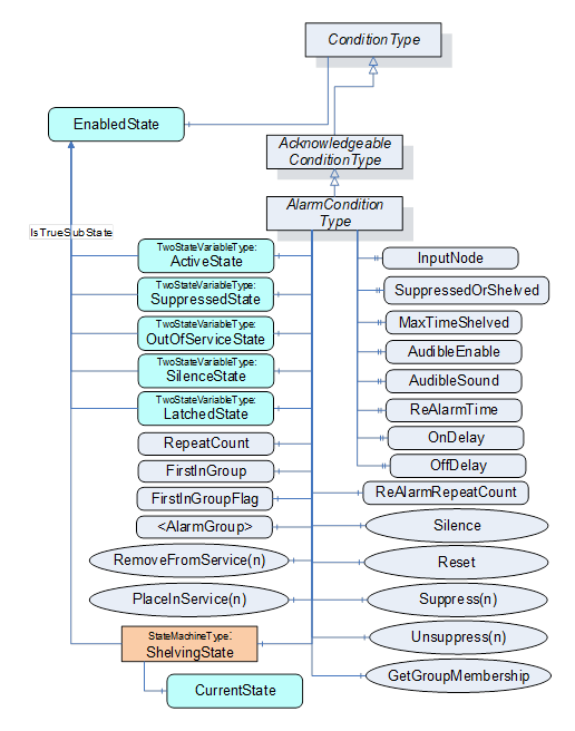
The Condition model is illustrated in Figure 10 and formally defined in the subsequent tables. It is worth noting that this figure, like all figures in this document, is not intended to be complete. Rather, the figures only illustrate information provided by the formal definitions.
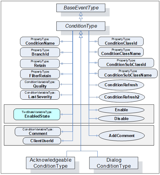
Figure 10 – Condition model
The ConditionType defines all general characteristics of a Condition. All other ConditionTypes derive from it. It is formally defined in Table 10 and Table 11. The False state of the EnabledState shall not be extended with a sub state machine.
Table 10 – ConditionType definition
|
Attribute |
Value |
||||
|
BrowseName |
ConditionType |
||||
|
IsAbstract |
True |
||||
|
References |
NodeClass |
BrowseName |
DataType |
TypeDefinition |
ModellingRule |
|
Subtype of the BaseEventType defined in 10000-5 |
|||||
|
HasSubtype |
ObjectType |
DialogConditionType |
Defined in Clause 5.6.2 |
||
|
HasSubtype |
ObjectType |
AcknowledgeableConditionType |
Defined in Clause 5.7.2 |
||
|
|
|
|
|
|
|
|
HasProperty |
Variable |
ConditionClassId |
NodeId |
PropertyType |
Mandatory |
|
HasProperty |
Variable |
ConditionClassName |
LocalizedText |
PropertyType |
Mandatory |
|
HasProperty |
Variable |
ConditionName |
String |
PropertyType |
Mandatory |
|
HasProperty |
Variable |
BranchId |
NodeId |
PropertyType |
Mandatory |
|
HasProperty |
Variable |
Retain |
Boolean |
PropertyType |
Mandatory |
|
HasProperty |
Variable |
SupportsFilteredRetain |
Boolean |
PropertyType |
|
|
HasComponent |
Variable |
EnabledState |
LocalizedText |
TwoStateVariableType |
Mandatory |
|
HasComponent |
Variable |
Quality |
StatusCode |
ConditionVariableType |
Mandatory |
|
HasComponent |
Variable |
LastSeverity |
UInt16 |
ConditionVariableType |
Mandatory |
|
HasComponent |
Variable |
Comment |
LocalizedText |
ConditionVariableType |
Mandatory |
|
HasProperty |
Variable |
ClientUserId |
String |
PropertyType |
Mandatory |
|
|
|
|
|
|
|
|
HasComponent |
Method |
Disable |
Defined in Clause 5.5.4 |
Mandatory |
|
|
HasComponent |
Method |
Enable |
Defined in Clause 5.5.5 |
Mandatory |
|
|
HasComponent |
Method |
AddComment |
Defined in Clause 5.5.6 |
Mandatory |
|
|
HasComponent |
Method |
ConditionRefresh |
Defined in Clause 5.5.7 |
|
|
|
HasComponent |
Method |
ConditionRefresh2 |
Defined in Clause 5.5.8 |
|
|
|
ConformanceUnits |
|||||
|
A & C Basic |
|||||
Table 11 – ConditionType Additional Subcomponents
|
BrowsePath |
References |
NodeClass |
BrowseName |
DataType |
TypeDefinition |
Others |
|
EnabledState |
HasProperty |
Variable |
TrueState |
LocalizedText |
PropertyType |
|
|
EnabledState |
HasProperty |
Variable |
FalseState |
LocalizedText |
PropertyType |
|
The empty “Others” column indicates that no ModellingRule applies.
The ConditionType inherits all Properties of the BaseEventType. Their semantic is defined in 10000-5. SourceNode Property identifies the ConditionSource. See 5.12 for more details. If the ConditionSource is not a Node in the AddressSpace, the NodeId is set to NULL. The SourceNode Property is the Node, which the Condition is associated with, it may be the same as the InputNode for an Alarm, but it may be a separate node. For example, a motor, which is a Variable with a Value that is an RPM, may be the ConditionSource for Conditions that are related to the motor as well as a temperature sensor associated with the motor. In the former the InputNode for the High RPM Alarm is the value of the Motor RPM, while in the later the InputNode of the High Alarm would be the value of the temperature sensor that is associated with the motor.
ConditionClassId, ConditionClassName, ConditionSubClassId and ConditionSubClassName originally defined in ConditionType are now defined in the BaseEventType (from which this type is derived). They are optional in the BaseEventType, but ConditionClassId, and ConditionClassName are Mandatory in ConditionType and thus listed (to update the modelling rule).
ConditionName identifies the Condition instance that the Event originated from. It can be used together with the SourceName in a user display to distinguish between different Condition instances. If a ConditionSource has only one instance of a ConditionType, and the Server has no instance name, the Server shall supply the name element of the BrowseName of the ConditionType.
BranchId is NULL for all Event Notifications that relate to the current state of the Condition instance. If BranchId is not NULL, it identifies a previous state of this Condition instance that still needs attention by an Operator. If the current ConditionBranch is transformed into a previous ConditionBranch then the Server needs to assign a non-NULL BranchId. An initial Event for the branch will generated with the values of the ConditionBranch and the new BranchId. The ConditionBranch can be updated many times before it is no longer needed. When the ConditionBranch no longer requires Operator input the final Event will have Retain set to False. The retain bit on the current Event is True, as long as any ConditionBranches require Operator input. See 4.2 for more information about the need for creating and maintaining previous ConditionBranches and Clause B.1 for an example using branches. The BranchId DataType is NodeId although the Server is not required to have ConditionBranches in the AddressSpace. The use of a NodeId allows the Server to use simple numeric identifiers, strings or arrays of bytes.
Retain when True describes a Condition (or ConditionBranch) as being in a state that is interesting for a Client wishing to synchronize its state with the Server’s state. The logic to determine how this flag is set is Server specific. Typically, all Active Alarms would have the Retain flag set; however, it is also possible for inactive Alarms to have their Retain flag set to True.
In normal processing when a Client receives an Event with the Retain flag set to False, the Client should consider this as a ConditionBranch that is no longer of interest, in the case of a “current Alarm display” the ConditionBranch would be removed from the display.
SupportsFilteredRetain Property is only provided on the ConditionType. When this Property is set to True on the Type, then the Server provides a Client specific Retain flag value taking into account any Client provided filter. When the property is False on the ConditionType then the Server does not provide a Client specific the value of the Retain flag. For example, if a Client applies a filter to exclude Alarms that are shelved, and the SupportsFilteredRetain is set to True, the Client receives an Alarm (it is not shelved, Retain is true). The Client (or another Client) shelves the Alarm. At this point the Alarm no longer passes the filter, but since the previous event was sent, this event is transmitted with Retain = False. For an example see B.1.4
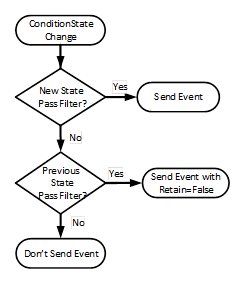
Figure 11 - SupportsFilteredRetain process
Figure 11 provides an illustration of the processing a Server shall follow for processing Retain flag when SupportsFilteredRetain flag is set to True.
EnabledState indicates whether the Condition is enabled. EnabledState/Id is True if enabled, False otherwise. EnabledState/TransitionTime defines when the EnabledState last changed. Recommended state names are described in A.1.
A Condition’s EnabledState effects the generation of Event Notifications and as such results in the following specific behaviour:
· When the Condition instance enters the Disabled state, the Retain Property of this Condition shall be set to False by the Server to indicate to the Client that the Condition instance is currently not of interest to Clients. This includes all ConditionBranches if any branches exist.
· When the Condition instance enters the enabled state, the Condition shall be evaluated and all of its Properties updated to reflect the current values. If this evaluation causes the Retain Property to transition to True for any ConditionBranch, then an Event Notification shall be generated for that ConditionBranch.
· The Server may choose to continue to test for a Condition instance while it is Disabled. However, no Event Notifications will be generated while the Condition instance is disabled.
· For any Condition that exists in the AddressSpace the Attributes and the following Variables will continue to have valid values even in the Disabled state; EventId, Event Type, Source Node, Source Name, Time, and EnabledState. Other Properties may no longer provide current valid values. All Variables that are no longer provided shall return a status of Bad_ConditionDisabled. The Event that reports the Disabled state should report the Properties as NULL or with a status of Bad_ConditionDisabled.
When enabled, changes to the following Variables shall cause a ConditionType Event Notification:
· Quality
· Severity (inherited from BaseEventType)
· Comment
This may not be the complete list. Subtypes of ConditionType may define additional Variables that trigger Event Notifications. In general, changes to Variables of the types TwoStateVariableType, ConditionVariableType, StateMachineType or any of their subtypes trigger Event Notifications and are not explicitly described in subtypes.
In the event of a restart of an AlarmManager, the AlarmManager shall recover the Enabled/Disabled states of all current conditions. If the system can not determine if the Condition is Enabled or Disabled, it shall be Enabled.
Quality reveals the status of process values or other resources that this Condition instance is based upon. If, for example, a process value is “Uncertain”, the associated “LevelAlarm” Condition is also questionable. Values for the Quality can be any of the OPC StatusCodes defined in 10000-8 as well as Good, Uncertain and Bad as defined in 10000-4. These StatusCodes are similar to but slightly more generic than the description of data quality in the various field bus specifications. It is the responsibility of the Server to map internal status information to these codes. A Server that supports no quality information shall return Good. This quality can also reflect the communication status associated with the system that this value or resource is based on and from which this Alarm was received. For communication errors to the underlying system, especially those that result in some unavailable Event fields, the quality shall be Bad_NoCommunication error.
Events are only generated for Conditions that have their Retain field set to True and for the initial transition of the Retain field from True to False.
LastSeverity provides the previous severity of the ConditionBranch. Initially this Variable contains a zero value; it will return a value only after a severity change. The new severity is supplied via the Severity Property, which is inherited from the BaseEventType.
Comment contains the last comment provided for a certain state (ConditionBranch) of a Condition. It may have been provided by an AddComment Method, some other Method or in some other manner. Any change in this field, shall trigger a new event to be generated. The initial value of this Variable is NULL, unless it is provided in some other manner.
ClientUserId is related to the Comment field and contains the identity of the user who inserted the most recent Comment. The logic to obtain the ClientUserId is defined in 10000-5.
The NodeId of the Condition instance is used as ConditionId. It is not explicitly modelled as a component of the ConditionType. However, it can be requested with the following SimpleAttributeOperand (see Table 12) in the SelectClause of the EventFilter: See 10000-4 for a detailed definition of the SelectClause in an Event Subscription.
Table 12 – ConditionId SimpleAttributeOperand Illustration
|
Name |
Type |
Description |
|
SimpleAttributeOperand |
|
|
|
typeId |
NodeId |
NodeId of the ConditionType Node |
|
browsePath[] |
QualifiedName |
empty |
|
attributeId |
IntegerId |
Id of the NodeId Attribute |
Conditions are Objects which have a state which changes over time. Each Condition instance has a ConditionId as an identifier which uniquely identifies it within the Server. This Condition (and it representative ConditionId) follows the same rules associated with Nodes (and their representative NodeIds) in the AddressSpace (see 10000-3). Therefore, once a Condition is created in a system that does not expose instances, any time that Condition is active it shall always have the same ConditionId. This allows higher level alarm management systems to operate on Conditions and to perform analysis of them.
A Condition instance may be an Object that appears in the Server Address Space. If this is the case the ConditionId shall be the NodeId for the Object.
The state of a Condition instance at any given time is the set values for the Variables that belong to the Condition instance. If one or more Variable values change the Server generates an Event with a unique EventId.
If a Client calls Refresh the Server will report the current state of a Condition instance by re-sending the last Event (i.e. the same EventId and Time is sent).
A ConditionBranch is a copy of the Condition instance state that can change independently of the current Condition instance state. Each Branch has an identifier called a BranchId which is unique among all active Branches for a Condition instance. Branches are typically not visible in the Address Space and this standard does not define a standard way to make them visible.
The Disable Method is used to change a Condition instance to the Disabled state. Normally, the NodeId of the object instance as the ObjectId is passed to the Call Service. However, some Servers do not expose Condition instances in the AddressSpace. Therefore, all Servers shall allow Clients to call the Disable Method by specifying ConditionId as the ObjectId. The Method cannot be called with an ObjectId of the ConditionType Node. Since Condition instances may not be defined in the AddressSpace, the MethodId that is passed in the Call Service shall be the NodeId of the Disable Method on the ConditionType.
Signature
Disable();
Method Result Codes in Table 13 (defined in Call Service)
Table 13 – Disable result codes
|
Result Code |
Description |
|
Bad_ConditionAlreadyDisabled |
See Table 137 for the description of this result code. |
Table 14 specifies the AddressSpace representation for the Disable Method.
Table 14 – Disable Method AddressSpace definition
|
Attribute |
Value |
||||
|
BrowseName |
Disable |
||||
|
References |
NodeClass |
BrowseName |
DataType |
TypeDefinition |
ModellingRule |
|
AlwaysGeneratesEvent |
ObjectType |
AuditConditionEnableEventType |
Defined in 5.10.2 |
||
|
ConformanceUnits |
|||||
|
A & C Enable |
|||||
If Auditing is supported, this Method shall generate an Event of AuditConditionEnableEventType for all invocations of the Method.
The Enable Method is used to change a Condition instance to the enabled state. Normally, the NodeId of the object instance as the ObjectId is passed to the Call Service. However, some Servers do not expose Condition instances in the AddressSpace. Therefore, all Servers shall allow Clients to call the Enable Method by specifying ConditionId as the ObjectId. The Method cannot be called with an ObjectId of the ConditionType Node. If the Condition instance is not exposed, then it may be difficult for a Client to determine the ConditionId for a disabled Condition. Since Condition instances may not be defined in the AddressSpace, the MethodId that is passed in the Call Service shall be the NodeId of the Enable Method on the ConditionType.
Signature
Enable();
Method result codes in Table 15 (defined in Call Service)
Table 15 – Enable result codes
|
Result Code |
Description |
|
Bad_ConditionAlreadyEnabled |
See Table 137 for the description of this result code. |
Table 16 specifies the AddressSpace representation for the Enable Method.
Table 16 – Enable Method AddressSpace definition
|
Attribute |
Value |
||||
|
BrowseName |
Enable |
||||
|
References |
NodeClass |
BrowseName |
DataType |
TypeDefinition |
ModellingRule |
|
AlwaysGeneratesEvent |
ObjectType |
AuditConditionEnableEventType |
Defined in 5.10.2 |
||
|
ConformanceUnits |
|||||
|
A & C Enable |
|||||
If Auditing is supported, this Method shall generate an Event of AuditConditionEnableEventType for all invocations of the Method.
The AddComment Method is used to apply a comment to a specific state of a Condition instance. Normally, the NodeId of the Object instance is passed as the ObjectId to the Call Service. However, some Servers do not expose Condition instances in the AddressSpace. Therefore, all Servers shall also allow Clients to call the AddComment Method by specifying ConditionId as the ObjectId. The Method cannot be called with an ObjectId of the ConditionType Node.
Signature
AddComment(
[in] ByteString EventId
[in] LocalizedText Comment
);
The parameters are defined in Table 17
Table 17 – AddComment arguments
|
Argument |
Description |
|
EventId |
EventId identifying a particular Event Notification where a state was reported for a Condition. |
|
Comment |
A localized text to be applied to the Condition. |
Method result codes in Table 18 (defined in Call Service)
Table 18 – AddComment result codes
|
Result Code |
Description |
|
Bad_MethodInvalid |
The MethodId provided does not correspond to the ObjectId provided. See 10000-4 for the general description of this result code. |
|
Bad_EventIdUnknown |
See Table 137 for the description of this result code. |
|
Bad_NodeIdInvalid |
Used to indicate that the specified ObjectId is not valid or that the Method was called on the ConditionType Node. See 10000-4 for the general description of this result code. |
Comments
Comments are added to Event occurrences identified via an EventId. EventIds where the related EventType is not a ConditionType (or subtype of it) and thus does not support Comments are rejected.
A ConditionEvent – where the Comment Variable contains this text – will be sent for the identified state. If a comment is added to a previous state (i.e. a state for which the Server has created a branch), the BranchId and all Condition values of this branch will be reported. If the comment field is NULL (both locale and text are empty) it will be ignored and any existing comments will remain unchanged. If the comment is to be reset, an empty text with a locale shall be provided.
Table 19 specifies the AddressSpace representation for the AddComment Method.
Table 19 – AddComment Method AddressSpace definition
|
Attribute |
Value |
||||
|
BrowseName |
AddComment |
||||
|
References |
NodeClass |
BrowseName |
DataType |
TypeDefinition |
ModellingRule |
|
HasProperty |
Variable |
InputArguments |
Argument[] |
PropertyType |
Mandatory |
|
AlwaysGeneratesEvent |
ObjectType |
AuditConditionCommentEventType |
Defined in 5.10.4 |
||
|
ConformanceUnits |
|||||
|
A & C Comment |
|||||
If Auditing is supported, this Method shall generate an Event of AuditConditionCommentEventType for all invocations of the Method.
ConditionRefresh allows a Client to request a Refresh of all Condition instances that currently are in an interesting state (they have the Retain flag set). This includes previous states of a Condition instance for which the Server maintains Branches. A Client would typically invoke this Method when it initially connects to a Server and following any situations, such as communication disruptions, in which it would require resynchronization with the Server. This Method is only available on the ConditionType. To invoke this Method, the call shall pass the well-known MethodId of the Method on the ConditionType and the ObjectId shall be the well-known NodeId of the ConditionType ObjectType.
Signature
ConditionRefresh(
[in] IntegerId SubscriptionId
);
The parameters are defined in Table 20
Table 20 – ConditionRefresh parameters
|
Argument |
Description |
|
SubscriptionId |
A valid Subscription Id of the Subscription to be refreshed. The Server shall verify that the SubscriptionId provided is part of the Session that is invoking the Method. |
Method result codes in Table 21 (defined in Call Service)
Table 21 – ConditionRefresh result codes
|
Result Code |
Description |
|
Bad_SubscriptionIdInvalid |
See 10000-4 for the description of this result code |
|
Bad_NothingToDo |
The ConditionRefresh Method was called on a SubscriptionId that has no event MonitoredItems. |
|
Bad_RefreshInProgress |
See Table 137 for the description of this result code |
|
Bad_UserAccessDenied |
The Method was not called in the context of the Session that owns the Subscription See 10000-4 for the general description of this result code. |
Comments
Sub clause 4.5 describes the concept, use cases and information flow in more detail.
The input argument provides a Subscription identifier indicating which Client Subscription shall be refreshed. If the Subscription is accepted the Server will react as follows:
1) The Server issues an event of RefreshStartEventType (defined in 5.11.2) marking the start of Refresh. A copy of the instance of RefreshStartEventType is queued into the Event stream for every Notifier MonitoredItem in the Subscription. Each of the Event copies shall contain the same EventId.
2) The Server issues Event Notifications of any Retained Conditions and Retained Branches of Conditions that meet the Subscriptions content filter criteria. Note that the EventId for such a refreshed Notification shall be identical to the one for the original Notification, the values of the other Properties are Server specific, in that some Servers may be able to replay the exact Events with all Properties/Variables maintaining the same values as originally sent, but other Servers might only be able to regenerate the Event. The regenerated Event might contain some updated Property/Variable values. For example, if the Alarm limits associated with a Variable were changed after the generation of the Event without generating a change in the Alarm state, the new limit might be reported. In another example, if the HighLimit was 100 and the Variable is 120. If the limit were changed to 90 no new Event would be generated since no change to the StateMachine, but the limit on a Refresh would indicate 90, when the original Event had indicated 100.
3) The Server may intersperse new Event Notifications that have not been previously issued to the Notifier along with those being sent as part of the Refresh request. Clients shall check for multiple Event Notifications for a ConditionBranch to avoid overwriting a new state delivered together with an older state from the Refresh process.
4) The Server issues an instance of RefreshEndEventType (defined in 5.11.3) to signal the end of the Refresh. A copy of the instance of RefreshEndEventType is queued into the Event stream for every Notifier MonitoredItem in the Subscription. Each of the Events copies shall contain the same EventId.
It is important to note that if multiple Event Notifiers are in a Subscription all Event Notifiers are processed. If a Client does not want all MonitoredItems refreshed, then the Client should place each MonitoredItem in a separate Subscription or call ConditionRefresh2 if the Server supports it.
If more than one Subscription is to be refreshed, then the standard call Service array processing can be used.
As mentioned above, ConditionRefresh shall also issue Event Notifications for prior states if they still need attention. In particular, this is True for Condition instances where previous states still need acknowledgement or confirmation.
Table 22 specifies the AddressSpace representation for the ConditionRefresh Method.
Table 22 – ConditionRefresh Method AddressSpace definition
|
Attribute |
Value |
||||
|
BrowseName |
ConditionRefresh |
||||
|
References |
NodeClass |
BrowseName |
DataType |
TypeDefinition |
ModellingRule |
|
HasProperty |
Variable |
InputArguments |
Argument[] |
PropertyType |
Mandatory |
|
AlwaysGeneratesEvent |
ObjectType |
RefreshStartEventType |
Defined in 5.11.2 |
||
|
AlwaysGeneratesEvent |
ObjectType |
RefreshEndEventType |
Defined in 5.11.3 |
||
|
ConformanceUnits |
|||||
|
A & C Refresh |
|||||
ConditionRefresh2 allows a Client to request a Refresh of all Condition instances that currently are in an interesting state (they have the Retain flag set) that are associated with the given Monitored item. In all other respects it functions as ConditionRefresh. A Client would typically invoke this Method when it initially connects to a Server and following any situations, such as communication disruptions where only a single MonitoredItem is to be resynchronized with the Server. This Method is only available on the ConditionType. To invoke this Method, the call shall pass the well-known MethodId of the Method on the ConditionType and the ObjectId shall be the well-known NodeId of the ConditionType ObjectType.
This Method is optional and as such Clients must be prepared to handle Servers which do not provide the Method. If the Method returns Bad_MethodInvalid, the Client shall revert to ConditionRefresh.
Signature
ConditionRefresh2(
[in] IntegerId SubscriptionId
[in] IntegerId MonitoredItemId
);
The parameters are defined in Table 23
Table 23 – ConditionRefresh2 parameters
|
Argument |
Description |
|
SubscriptionId |
The identifier of the Subscription containing the MonitoredItem to be refreshed. The Server shall verify that the SubscriptionId provided is part of the Session that is invoking the Method. |
|
MonitoredItemId |
The identifier of the MonitoredItem to be refreshed. The MonitoredItemId shall be in the provided Subscription. |
Method result codes in Table 24(defined in Call Service)
Table 24 – ConditionRefresh2 result codes
|
Result Code |
Description |
|
Bad_SubscriptionIdInvalid |
See 10000-4 for the description of this result code |
|
Bad_MonitoredItemIdInvalid |
See 10000-4 for the description of this result code |
|
Bad_RefreshInProgress |
See Table 137 for the description of this result code |
|
Bad_UserAccessDenied |
The Method was not called in the context of the Session that owns the Subscription See 10000-4 for the general description of this result code. |
|
Bad_MethodInvalid |
See 10000-4 for the description of this result code |
Comments
Sub clause 4.5 describes the concept, use cases and information flow in more detail.
The input argument provides a Subscription identifier and MonitoredItem identifier indicating which MonitoredItem in the selected Client Subscription shall be refreshed. If the Subscription and MonitoredItem is accepted the Server will react as follows:
1) The Server issues a RefreshStartEvent (defined in 5.11.2) marking the start of Refresh. The RefreshStartEvent is queued into the Event stream for the Notifier MonitoredItem in the Subscription.
2) The Server issues Event Notifications of any Retained Conditions and Retained Branches of Conditions that meet the Subscriptions content filter criteria. Note that the EventId for such a refreshed Notification shall be identical to the one for the original Notification, the values of the other Properties are Server specific, in that some Servers may be able to replay the exact Events with all Properties/Variables maintaining the same values as originally sent, but other Servers might only be able to regenerate the Event. The regenerated Event might contain some updated Property/Variable values. For example, if the Alarm limits associated with a Variable were changed after the generation of the Event without generating a change in the Alarm state, the new limit might be reported. In another example, if the HighLimit was 100 and the Variable is 120. If the limit were changed to 90 no new Event would be generated since no change to the StateMachine, but the limit on a Refresh would indicate 90, when the original Event had indicated 100.
3) The Server may intersperse new Event Notifications that have not been previously issued to the notifier along with those being sent as part of the Refresh request. Clients shall check for multiple Event Notifications for a ConditionBranch to avoid overwriting a new state delivered together with an older state from the Refresh process.
4) The Server issues a RefreshEndEvent (defined in 5.11.3) to signal the end of the Refresh. The RefreshEndEvent is queued into the Event stream for the Notifier MonitoredItem in the Subscription.
If more than one MonitoredItem or Subscription is to be refreshed, then the standard call Service array processing can be used.
As mentioned above, ConditionRefresh2 shall also issue Event Notifications for prior states if those states still need attention. In particular, this is True for Condition instances where previous states still need acknowledgement or confirmation.
Table 25 specifies the AddressSpace representation for the ConditionRefresh2 Method.
Table 25 – ConditionRefresh2 Method AddressSpace definition
|
Attribute |
Value |
||||
|
BrowseName |
ConditionRefresh2 |
||||
|
References |
NodeClass |
BrowseName |
DataType |
TypeDefinition |
ModellingRule |
|
HasProperty |
Variable |
InputArguments |
Argument[] |
PropertyType |
Mandatory |
|
AlwaysGeneratesEvent |
ObjectType |
RefreshStartEventType |
Defined in 5.11.2 |
||
|
AlwaysGeneratesEvent |
ObjectType |
RefreshEndEventType |
Defined in 5.11.3 |
||
|
ConformanceUnits |
|||||
|
A & C Refresh2 |
|||||
The Dialog Model is an extension of the Condition model used by a Server to request user input. It provides functionality similar to the standard Message dialogs found in most operating systems. The model can easily be customized by providing Server specific response options in the ResponseOptionSet and by adding additional functionality to derived Condition Types.
The DialogConditionType is used to represent Conditions as dialogs. It is illustrated in Figure 12 and formally defined in Table 26 and Table 27.
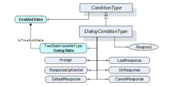
Figure 12 – DialogConditionType Overview
Table 26 – DialogConditionType definition
|
Attribute |
Value |
||||
|
BrowseName |
DialogConditionType |
||||
|
IsAbstract |
False |
||||
|
References |
NodeClass |
BrowseName |
DataType |
TypeDefinition |
Modelling |
|
Subtype of the ConditionType defined in clause 5.5.2 |
|||||
|
HasComponent |
Variable |
DialogState |
LocalizedText |
TwoStateVariableType |
Mandatory |
|
HasProperty |
Variable |
Prompt |
LocalizedText |
PropertyType |
Mandatory |
|
HasProperty |
Variable |
ResponseOptionSet |
LocalizedText [ ] |
PropertyType |
Mandatory |
|
HasProperty |
Variable |
DefaultResponse |
Int32 |
PropertyType |
Mandatory |
|
HasProperty |
Variable |
LastResponse |
Int32 |
PropertyType |
Mandatory |
|
HasProperty |
Variable |
OkResponse |
Int32 |
PropertyType |
Mandatory |
|
HasProperty |
Variable |
CancelResponse |
Int32 |
PropertyType |
Mandatory |
|
HasComponent |
Method |
Respond |
Defined in Clause 5.6.3. |
Mandatory |
|
|
HasComponent |
Method |
Respond2 |
Defined in Clause 5.6.4. |
Optional |
|
|
A & C Dialog |
|||||
Table 27 – DialogConditionType Additional Subcomponents
|
BrowsePath |
References |
NodeClass |
BrowseName |
DataType |
TypeDefinition |
Others |
|
DialogState |
HasProperty |
Variable |
TrueState |
LocalizedText |
PropertyType |
|
|
DialogState |
HasProperty |
Variable |
FalseState |
LocalizedText |
PropertyType |
|
The empty “Others” column indicates that no ModellingRule applies.
The DialogConditionType inherits all Properties of the ConditionType.
DialogState/Id when set to True indicates that the Dialog is active and waiting for a response. Recommended state names are described in A.2.
Prompt is a dialog prompt to be shown to the user.
ResponseOptionSet specifies the desired set of responses as array of LocalizedText. The index in this array is used for the corresponding fields like DefaultResponse, LastResponse and SelectedOption in the Respond Method. The recommended localized names for the common options are described in A.1.
Typical combinations of response options are
· OK
· OK, Cancel
· Yes, No, Cancel
· Abort, Retry, Ignore
· Retry, Cancel
· Yes, No
DefaultResponse identifies the response option that should be shown as default to the user. It is the index in the ResponseOptionSet array. If no response option is the default, the value of the Property is -1.
LastResponse contains the last response provided by a Client in the Respond Method. If no previous response exists, then the value of the Property is -1.
OkResponse provides the index of the OK option in the ResponseOptionSet array. This choice is the response that will allow the system to proceed with the operation described by the prompt. This allows a Client to identify the OK option if a special handling for this option is available. If no OK option is available, the value of this Property is -1.
CancelResponse provides the index of the response in the ResponseOptionSet array that will cause the Dialog to go into the inactive state without proceeding with the operation described by the prompt. This allows a Client to identify the Cancel option if a special handling for this option is available. If no Cancel option is available, the value of this Property is -1.
Respond is used to pass the selected response option and end the dialog. DialogState/Id will return to False.
Signature
Respond(
[in] Int32 SelectedResponse
);
The parameters are defined in Table 28
Table 28 – Respond parameters
|
Argument |
Description |
|
SelectedResponse |
Selected index of the ResponseOptionSet array. |
Method result codes in Table 29 (defined in Call Service)
Table 29 – Respond Result Codes
|
Result Code |
Description |
|
Bad_DialogNotActive |
See Table 137 for the description of this result code. |
|
Bad_DialogResponseInvalid |
See Table 137 for the description of this result code. |
Table 30 specifies the AddressSpace representation for the Respond Method.
Table 30 – Respond Method AddressSpace definition
|
Attribute |
Value |
||||
|
BrowseName |
Respond |
||||
|
References |
NodeClass |
BrowseName |
DataType |
TypeDefinition |
ModellingRule |
|
HasProperty |
Variable |
InputArguments |
Argument[] |
PropertyType |
Mandatory |
|
AlwaysGeneratesEvent |
ObjectType |
AuditConditionRespondEventType |
Defined in 5.10.5
|
||
|
ConformanceUnits |
|||||
|
A & C Dialog |
|||||
If Auditing is supported, this Method shall generate an Event of AuditConditionRespondEventType for all invocations of the Method.
Respond2 Method extends the respond method by adding a comment field. For other functionality see the Respond Method definition.
Signature
Respond2(
[in] Int32 SelectedResponse
[in] LocalizedText Comment
);
The parameters are defined in Table 31
Table 31 – Respond2 parameters
|
Argument |
Description |
|
SelectedResponse |
Selected index of the ResponseOptionSet array. |
|
Comment |
A localized text to be applied to the Dialog. |
If the Comment argument is NULL (both locale and text are empty) it will be ignored and any existing comments will remain unchanged. If the comment is to be reset, an empty text with a locale shall be provided.
Method result codes in Table 32 (defined in Call Service)
Table 32 – Respond2 Result Codes
|
Result Code |
Description |
|
Bad_DialogNotActive |
See Table 137 for the description of this result code. |
|
Bad_DialogResponseInvalid |
See Table 137 for the description of this result code. |
Table 33 specifies the AddressSpace representation for the Respond2 Method.
Table 33 – Respond2 Method AddressSpace definition
|
Attribute |
Value |
||||
|
BrowseName |
Respond2 |
||||
|
References |
NodeClass |
BrowseName |
DataType |
TypeDefinition |
ModellingRule |
|
HasProperty |
Variable |
InputArguments |
Argument[] |
PropertyType |
Mandatory |
|
AlwaysGeneratesEvent |
ObjectType |
AuditConditionRespondEventType |
Defined in 5.10.5
|
||
|
ConformanceUnits |
|||||
|
A & C Dialog2 |
|||||
If Auditing is supported, this Method shall generate an Event of AuditConditionRespondEventType for all invocations of the Method.
The Acknowledgeable Condition Model extends the Condition model. States for acknowledgement and confirmation are added to the Condition model.
AcknowledgeableConditions are represented by the AcknowledgeableConditionType which is a subtype of the ConditionType. The model is formally defined in the following sub clauses.
The AcknowledgeableConditionType extends the ConditionType by defining acknowledgement characteristics. The AcknowledgeableConditionType is illustrated in Figure 13 and formally defined in Table 34 and Table 35.
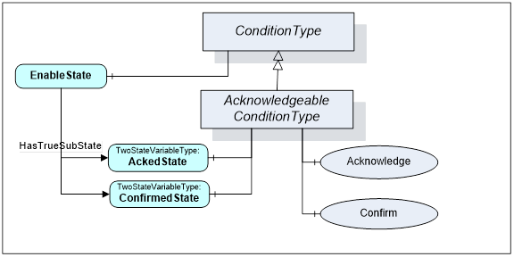
Figure 13 – AcknowledgeableConditionType overview
Table 34 – AcknowledgeableConditionType definition
|
Attribute |
Value |
||||
|
BrowseName |
AcknowledgeableConditionType |
||||
|
IsAbstract |
False |
||||
|
References |
NodeClass |
BrowseName |
DataType |
TypeDefinition |
ModellingRule |
|
Subtype of the ConditionType defined in clause 5.5.2. |
|||||
|
HasSubtype |
ObjectType |
AlarmConditionType |
Defined in Clause 5.8.2 |
||
|
|
|
|
|
|
|
|
HasComponent |
Variable |
AckedState |
LocalizedText |
TwoStateVariableType |
Mandatory |
|
HasComponent |
Variable |
ConfirmedState |
LocalizedText |
TwoStateVariableType |
Optional |
|
|
|
|
|
|
|
|
HasComponent |
Method |
Acknowledge |
Defined in Clause 5.7.3 |
Mandatory |
|
|
HasComponent |
Method |
Confirm |
Defined in Clause 5.7.4 |
Optional |
|
|
ConformanceUnits |
|||||
|
A & C Acknowledge |
|||||
Table 35 – AcknowledgeableConditionType Additional Subcomponents
|
BrowsePath |
References |
NodeClass |
BrowseName |
DataType |
TypeDefinition |
Others |
|
AckedState |
HasProperty |
Variable |
TrueState |
LocalizedText |
PropertyType |
|
|
AckedState |
HasProperty |
Variable |
FalseState |
LocalizedText |
PropertyType |
|
|
ConfirmedState |
HasProperty |
Variable |
TrueState |
LocalizedText |
PropertyType |
|
|
ConfirmedState |
HasProperty |
Variable |
FalseState |
LocalizedText |
PropertyType |
|
The empty “Others” column indicates that no ModellingRule applies.
The AcknowledgeableConditionType inherits all Properties of the ConditionType.
AckedState when False indicates that the Condition instance requires acknowledgement for the reported Condition state. When the Condition instance is acknowledged the AckedState is set to True. ConfirmedState indicates whether it requires confirmation. Recommended state names are described in A.1. The two states are sub-states of the True EnabledState. See 4.3 for more information about acknowledgement and confirmation models. The EventId used in the Event Notification is considered the identifier of this state and has to be used when calling the Methods for acknowledgement or confirmation.
A Server may require that previous states be acknowledged. If the acknowledgement of a previous state is still open and a new state also requires acknowledgement, the Server shall create a branch of the Condition instance as specified in 4.2. Clients are expected to keep track of all ConditionBranches where AckedState/Id is False to allow acknowledgement of those. See also 5.5.2 for more information about ConditionBranches and the examples in Clause B.1. The handling of the AckedState and branches also applies to the ConfirmedState.
In the event of a restart of an AlarmManager, the AlarmManager should recover the AckedState and ConfirmedState (if supported) of all current conditions. If the system can not determine if the condition is Acknowledged or Confirmed, they shall be set to false (not Acknowledged and not Confirmed).
The Acknowledge Method is used to acknowledge an Event Notification for a Condition instance state where AckedState is False. Normally, the NodeId of the object instance is passed as the ObjectId to the Call Service. However, some Servers do not expose Condition instances in the AddressSpace. Therefore, Servers shall allow Clients to call the Acknowledge Method by specifying ConditionId as the ObjectId. The Method cannot be called with an ObjectId of the AcknowledgeableConditionType Node.
Signature
Acknowledge(
[in] ByteString EventId
[in] LocalizedText Comment
);
The parameters are defined in Table 36
Table 36 – Acknowledge parameters
|
Argument |
Description |
|
EventId |
EventId identifying a particular Event Notification. Only Event Notifications where AckedState/Id was False can be acknowledged. |
|
Comment |
A localized text to be applied to the Condition. |
Method result codes in Table 37 (defined in Call Service)
Table 37 – Acknowledge result codes
|
Result Code |
Description |
|
Bad_ConditionBranchAlreadyAcked |
See Table 137 for the description of this result code. |
|
Bad_MethodInvalid |
The MethodId is not the well-known method of the AcknowledgeableConditionType or MethodId does not refer to a Method for the specified Object or ConditionId. |
|
Bad_EventIdUnknown |
See Table 137 for the description of this result code. |
|
Bad_NodeIdInvalid |
Used to indicate that the specified ObjectId is not valid or that the Method was called on the AcknowledgeableConditionType Node. See 10000-4 for the general description of this result code. |
Comments
A Server is responsible to ensure that each Event has a unique EventId. This allows Clients to identify and acknowledge a particular Event Notification.
The EventId identifies a specific Event Notification where a state to be acknowledged was reported. Acknowledgement and the optional comment will be applied to the state identified with the EventId. If the comment field is NULL (both locale and text are empty) it will be ignored and any existing comments will remain unchanged. If the comment is to be reset, an empty text with a locale shall be provided.
A valid EventId will result in an Event Notification where AckedState/Id is set to True and the Comment Property contains the text of the optional comment argument. If a previous state is acknowledged, the BranchId and all Condition values of this branch will be reported. Table 38 specifies the AddressSpace representation for the Acknowledge Method.
Table 38 – Acknowledge Method AddressSpace definition
|
Attribute |
Value |
||||
|
BrowseName |
Acknowledge |
||||
|
References |
NodeClass |
BrowseName |
DataType |
TypeDefinition |
ModellingRule |
|
HasProperty |
Variable |
InputArguments |
Argument[] |
PropertyType |
Mandatory |
|
AlwaysGeneratesEvent |
ObjectType |
AuditConditionAcknowledge EventType |
Defined in 5.10.5 |
||
|
ConformanceUnits |
|||||
|
A & C Acknowledge |
|||||
If Auditing is supported, this Method shall generate an Event of AuditConditionAcknowledgeEventType for all invocations of the Method.
The Confirm Method is used to confirm an Event Notifications for a Condition instance state where ConfirmedState is False. Normally, the NodeId of the object instance is passed as the ObjectId to the Call Service. However, some Servers do not expose Condition instances in the AddressSpace. Therefore, Servers shall allow Clients to call the Confirm Method by specifying ConditionId as the ObjectId. The Method cannot be called with an ObjectId of the AcknowledgeableConditionType Node.
Signature
Confirm(
[in] ByteString EventId
[in] LocalizedText Comment
);
The parameters are defined in Table 39
Table 39 – Confirm Method parameters
|
Argument |
Description |
|
EventId |
EventId identifying a particular Event Notification. Only Event Notifications where the Id property of the ConfirmedState is False can be confirmed. |
|
Comment |
A localized text to be applied to the Conditions. |
Method result codes in Table 40 (defined in Call Service)
Table 40 – Confirm result codes
|
Result Code |
Description |
|
Bad_ConditionBranchAlreadyConfirmed |
See Table 137 for the description of this result code. |
|
Bad_MethodInvalid |
The method id does not refer to a method for the specified object or ConditionId. See 10000-4 for the general description of this result code. |
|
Bad_EventIdUnknown |
See Table 137 for the description of this result code. |
|
Bad_NodeIdInvalid |
Used to indicate that the specified ObjectId is not valid or that the Method was called on the AcknowledgeableConditionType Node. See 10000-4 for the general description of this result code. |
Comments
A Server is responsible to ensure that each Event has a unique EventId. This allows Clients to identify and confirm a particular Event Notification.
The EventId identifies a specific Event Notification where a state to be confirmed was reported. A Comment can be provided which will be applied to the state identified with the EventId. If the comment field is NULL (both locale and text are empty) it will be ignored and any existing comments will remain unchanged. If the comment is to be reset, an empty text with a locale shall be provided.
A valid EventId will result in an Event Notification where ConfirmedState/Id is set to True and the Comment Property contains the text of the optional comment argument. If a previous state is confirmed, the BranchId and all Condition values of this branch will be reported. A Client can confirm only events that have a ConfirmedState/Id set to False. The logic for setting ConfirmedState/Id to False is Server specific and may even be event or condition specific.
Table 41 specifies the AddressSpace representation for the Confirm Method.
Table 41 – Confirm Method AddressSpace definition
|
Attribute |
Value |
||||
|
BrowseName |
Confirm |
||||
|
References |
NodeClass |
BrowseName |
DataType |
TypeDefinition |
ModellingRule |
|
HasProperty |
Variable |
InputArguments |
Argument[] |
PropertyType |
Mandatory |
|
AlwaysGeneratesEvent |
ObjectType |
AuditConditionConfirmEventType |
Defined in 5.10.7
|
||
|
ConformanceUnits |
|||||
|
A & C Confirm |
|||||
If Auditing is supported, this Method shall generate an Event of AuditConditionConfirmEventType for all invocations of the Method.
Figure 14 informally describes the AlarmConditionType, its sub-types and where it is in the hierarchy of Event Types.
Figure 14 – AlarmConditionType Hierarchy Model
The AlarmConditionType extends the AcknowledgeableConditionType by introducing an ActiveState, SuppressedState and ShelvingState. It also adds the ability to set a delay time, re-alarm time, Alarm groups and audible Alarm settings. The Alarm model is illustrated in Figure 15. This illustration is not intended to be a complete definition. It is formally defined in Table 42 and Table 43.
Figure 15 – Alarm Model
Table 42 – AlarmConditionType definition
|
Attribute |
Value |
||||
|
BrowseName |
AlarmConditionType |
||||
|
IsAbstract |
False |
||||
|
References |
Node Class |
BrowseName |
DataType |
TypeDefinition |
Modelling Rule |
|
Subtype of the AcknowledgeableConditionType defined in clause 5.7.2 |
|||||
|
HasComponent |
Variable |
ActiveState |
LocalizedText |
TwoStateVariableType |
Mandatory |
|
HasProperty |
Variable |
InputNode |
NodeId |
PropertyType |
Mandatory |
|
HasComponent |
Variable |
SuppressedState |
LocalizedText |
TwoStateVariableType |
Optional |
|
HasComponent |
Variable |
OutOfServiceState |
LocalizedText |
TwoStateVariableType |
Optional |
|
HasComponent |
Object |
ShelvingState |
|
ShelvedStateMachineType |
Optional |
|
HasProperty |
Variable |
SuppressedOrShelved |
Boolean |
PropertyType |
Mandatory |
|
HasProperty |
Variable |
MaxTimeShelved |
Duration |
PropertyType |
Optional |
|
|
|
|
|
|
|
|
HasProperty |
Variable |
AudibleEnabled |
Boolean |
PropertyType |
Optional |
|
HasComponent |
Variable |
AudibleSound |
AudioDataType |
AudioVariableType |
Optional |
|
HasComponent |
Variable |
SilenceState |
LocalizedText |
TwoStateVariableType |
Optional |
|
|
|
|
|
|
|
|
HasProperty |
Variable |
OnDelay |
Duration |
PropertyType |
Optional |
|
HasProperty |
Variable |
OffDelay |
Duration |
PropertyType |
Optional |
|
|
|
|
|
|
|
|
HasComponent |
Variable |
FirstInGroupFlag |
Boolean |
BaseDataVariableType |
Optional |
|
HasComponent |
Object |
FirstInGroup |
|
AlarmGroupType |
Optional |
|
HasComponent |
Variable |
LatchedState |
LocalizedText |
TwoStateVariableType |
Optional |
|
HasAlarmSuppressionGroup |
Object |
<AlarmGroup> |
|
AlarmGroupType |
OptionalPlaceholder |
|
HasProperty |
Variable |
ReAlarmTime |
Duration |
PropertyType |
Optional |
|
HasComponent |
Variable |
ReAlarmRepeatCount |
Int16 |
BaseDataVariableType |
Optional |
|
|
|
|
|
|
|
|
HasComponent |
Method |
Reset |
Defined in 5.8.5 |
Optional |
|
|
HasComponent |
Method |
Reset2 |
Defined in 5.8.65.8.5 |
Optional |
|
|
HasComponent |
Method |
Silence |
Defined in 5.8.7 |
Optional |
|
|
HasComponent |
Method |
Suppress |
Defined in 5.8.8 |
Optional |
|
|
HasComponent |
Method |
Suppress2 |
Defined in 5.8.9 |
Optional |
|
|
HasComponent |
Method |
Unsuppress |
Defined in 5.8.10 |
Optional |
|
|
HasComponent |
Method |
Unsuppress2 |
Defined in 5.8.11 |
Optional |
|
|
HasComponent |
Method |
RemoveFromService |
Defined in 5.8.12 |
Optional |
|
|
HasComponent |
Method |
RemoveFromService2 |
Defined in 5.8.13 |
Optional |
|
|
HasComponent |
Method |
PlaceInService |
Defined in 5.8.14 |
Optional |
|
|
HasComponent |
Method |
PlaceInService2 |
Defined in 5.8.15 |
Optional |
|
|
HasComponent |
Method |
GetGroupMemberships |
Defined in 5.8.16 |
Optional |
|
|
|
|
|
|
|
|
|
HasSubtype |
ObjectType |
DiscreteAlarmType |
|
|
|
|
HasSubtype |
ObjectType |
LimitAlarmType |
|
|
|
|
HasSubtype |
ObjectType |
DiscrepancyAlarmType |
|
|
|
|
|
|||||
|
ConformanceUnits |
|||||
|
A & C Alarm |
|||||
Table 43 – AlarmConditionType Additional Subcomponents
|
BrowsePath |
References |
NodeClass |
BrowseName |
DataType |
TypeDefinition |
Others |
|
ActiveState |
HasProperty |
Variable |
TrueState |
LocalizedText |
PropertyType |
|
|
ActiveState |
HasProperty |
Variable |
FalseState |
LocalizedText |
PropertyType |
|
|
SuppressedState |
HasProperty |
Variable |
TrueState |
LocalizedText |
PropertyType |
|
|
SuppressedState |
HasProperty |
Variable |
FalseState |
LocalizedText |
PropertyType |
|
|
OutOfServiceState |
HasProperty |
Variable |
TrueState |
LocalizedText |
PropertyType |
|
|
OutOfServiceState |
HasProperty |
Variable |
FalseState |
LocalizedText |
PropertyType |
|
|
SilenceState |
HasProperty |
Variable |
TrueState |
LocalizedText |
PropertyType |
|
|
SilenceState |
HasProperty |
Variable |
FalseState |
LocalizedText |
PropertyType |
|
|
LatchedState |
HasProperty |
Variable |
TrueState |
LocalizedText |
PropertyType |
|
|
LatchedState |
HasProperty |
Variable |
FalseState |
LocalizedText |
PropertyType |
|
The empty “Others” column indicates that no ModellingRule applies.
The AlarmConditionType inherits all Properties of the AcknowledgeableConditionType. The following states are sub-states of the True EnabledState.
ActiveState/Id when set to True indicates that the situation the Condition is representing currently exists. When a Condition instance is in the inactive state (ActiveState/Id when set to False) it is representing a situation that has returned to a normal state. The transitions of Conditions to the inactive and Active states are triggered by Server specific actions. Subtypes of the AlarmConditionType specified later in this document will have sub-state models that further define the Active state. Recommended state names are described inA.1. In the event of a restart of an AlarmManager, the AlarmManager shall recover the ActiveState.
The InputNode Property provides the NodeId of the Variable the Value of which is used as primary input in the calculation of the Alarm state. If this Variable is not in the AddressSpace, a NULL NodeId shall be provided. In some systems, an Alarm may be calculated based on multiple Variables Values; it is up to the system to determine which Variable’s NodeId is used.
SuppressedState, OutOfServiceState and ShelvingState together allow the suppression of Alarms on display systems. These three suppressions are generally used by different personnel or systems at a plant, i.e. automatic systems, maintenance personnel and Operators.
SuppressedState is used internally by a Server to automatically suppress Alarms due to system specific reasons. For example, a system may be configured to suppress Alarms that are associated with machinery that is in a state such as shutdown. For example, a low level Alarm for a tank that is currently not in use might be suppressed. Recommended state names are described in A.1. In the event of a restart of an AlarmManager, the AlarmManager should recover the SuppressedState. If the system cannot determine if the alarm is Suppressed, the state shall be set to false (not Suppressed).
OutOfServiceState is used by maintenance personnel to suppress Alarms due to a maintenance issue. For example, if an instrument is taken out of service for maintenance or is removed temporarily while it is being replaced or serviced the item would have the OutOfServiceState set. Recommended state names are described in A.1. In the event of a restart of an AlarmManager, the AlarmManager should recover the OutOfServiceState. If the system cannot determine if the alarm is OutOfService, the state shall be set to false (not OutOfService).
ShelvingState suggests whether an Alarm shall (temporarily) be prevented from being displayed to the user. It is quite often used by Operators to block nuisance Alarms. The ShelvingState is defined in 5.8.17.
When an Alarm has any or all of the SuppressedState, OutOfServiceState or ShelvingState set to True, the SuppressedOrShelved property shall be set True and this Alarm is then typically not displayed by the Client. State transitions associated with the Alarm do occur, but they are not typically displayed by the Clients as long as the Alarm remains in any of the SuppressedState, OutOfServiceState or Shelved state.
The optional Property MaxTimeShelved is used to set the maximum time that an Alarm Condition may be shelved. The value is expressed as duration. Systems can use this Property to prevent permanent Shelving of an Alarm. If this Property is present, it will be an upper limit on the duration passed into a TimedShelve Method call. If a value that exceeds the value of this Property is passed to the TimedShelve Method, then a Bad_ShelvingTimeOutOfRange error code is returned on the call. If this Property is present, it will also be enforced for the OneShotShelved state, in that an Alarm Condition will transition to the Unshelved state from the OneShotShelved state if the duration specified in this Property expires following a OneShotShelve operation without a change of any of the other items associated with the Condition.
The optional Property AudibleEnabled is a Boolean that indicates if the current state of this Alarm includes an audible Alarm.
The optional Property AudibleSound contains the sound file that is to be played if an audible Alarm is to be generated. This file would be play/generated as long as the Alarm is active and unacknowledged, unless the silence StateMachine is included, in which case it may also be silenced by this StateMachine.
The SilenceState is used to suppress the generation of audible Alarms. Typically, it is used when an Operator silences all Alarms on a screen, but needs to acknowledge the Alarms individually. Silencing an Alarm shall silence the Alarm on all systems (screens) that it is being reported on. Not all Clients will make use of this StateMachine, but it allows multiple Clients to synchronize audible Alarm states. Acknowledging an Alarm shall automatically silence an Alarm. In the event of a restart of an AlarmManager, the AlarmManager should recover the SilenceState. If the system cannot determine if the Alarm is silenced, it shall set the SilenceState, based on the AcknowledgeState. If it is Acknowledged, it is silenced, If it has not been Acknowledged, it shall not be silenced.
The OnDelay and OffDelay Properties can be used to eliminate nuisance Alarms. The OnDelay is used to avoid unnecessary Alarms when a signal temporarily overshoots its setpoint, thus preventing the Alarm from being triggered until the signal remains in the Alarm state continuously for a specified length of time (OnDelay time). The OffDelay is used to reduce chattering Alarms by locking the Alarm indication for a certain holding period after the condition has returned to normal. I.e., the Alarm shall stay active for the OffDelay time and shall not regenerate if it returns to active in that period. If the Alarm remains in the inactive zone for OffDelay it will then become inactive.
The optional variable FirstInGroupFlag is used together with the FirstInGroup object. The FirstInGroup Object is an instance of an AlarmGroupType that groups a number of related Alarms. The FirstInGroupFlag is set on the Alarm instance that was the first Alarm to trigger in a FirstInGroup. If this variable is present, then the FirstInGroup shall also be present. These two nodes allow an alarming system to determine which Alarm in the list was the trigger. It is commonly used in situations where Alarms are interrelated and usually multiple Alarms occur. For example, vibration sensors in a turbine, usually all sensors trigger if any one triggers, but what is important for an Operator is the first sensor that triggered.
The LatchedState Object, if present, indicates that this Alarm supports being latched. The Alarm will remain with a retain bit of True until it is no longer active, is acknowledged, is confirmed (if ConfirmedState is provided) and is reset. The Reset Method, if called while active has no effect on the Alarm and is ignored and an error of Bad_InvalidState is return on the call. The Object indicates the current state, latched or not latched. Recommended state names are described in A.1. If this Object is provided the Reset Method must also be provided. In the event of a restart of an AlarmManager, the AlarmManager shall recover the LatchedState.
An Alarm instance may contain HasAlarmSuppressionGroup reference(s) to instance(s) of AlarmGroupType (or subtype of it). Each instance is an AlarmSuppressionGroup. When an AlarmSuppressionGroup goes active, the Server shall set the SuppressedState of the Alarm containing the HasAlarmSuppressionGroup reference to True. When all of referenced AlarmSuppressionGroups are no longer active, then the Server shall set SuppressedState to False. A single AlarmSuppressionGroup can manage multiple Alarms. AlarmSuppressionGroups are used to control Alarm floods and to help manage Alarms.
ReAlarmTime if present sets a time that is used to bring an Alarm back to the top of an Alarm list. If an Alarm has not returned to normal within the provided time (from when it last was alarmed), the Server will generate a new Alarm for it (as if it just went into alarm). If it has been silenced it shall return to an un-silenced state, if it has been acknowledged it shall return to unacknowledged. The Alarm active time is set to the time of the re-alarm.
ReAlarmRepeatCount if present counts the number times an Alarm was re-alarmed. Some smart alarming system would use this count to raise the priority or otherwise generate additional or different annunciations for the given Alarm. The count is reset when an Alarm returns to normal.
Silence Method can be used to silence an instance of an Alarm. It is defined in 5.8.7.
Suppress and Suppress2 Method can be used to suppress an instance of an Alarm. Most Alarm suppression occurs via advanced alarming, but this method allows additional access to suppress a particular Alarm instance. Additional details are provided in the definition in 5.8.8 and 5.8.9
Unsuppress and Unsuppress2 Method can be used to remove an instance of an Alarm from SuppressedState. Additional details are provided in the definition in 5.8.10 and 5.8.11.
PlaceInService and PlaceInService2 Method can be used to remove an instance of an Alarm from OutOfServiceState. It is defined in 5.8.14 and 5.8.15.
RemoveFromService and RemoveFromService2 Method can be used to place an instance of an Alarm in OutOfServiceState. It is defined in 5.8.12 and 5.8.13.
Reset Method is used to clear a latched Alarm. It is defined in 5.8.5. If this Object is provided the LatchedState Object shall also be provided.
More details about the Alarm Model and the various states can be found in Sub clause 4.8. and in Annex E.
The AlarmGroupType provides a simple manner of grouping Alarms. This grouping can be used for Alarm suppression or for identifying related Alarms. The actual usage of the AlarmGroupType is specified where it is used.
Table 44 – AlarmGroupType definition
|
Attribute |
Value |
||||
|
BrowseName |
AlarmGroupType |
||||
|
IsAbstract |
False |
||||
|
References |
NodeClass |
BrowseName |
DataType |
TypeDefinition |
Modelling |
|
Subtype of the FolderType defined in 10000-5 |
|||||
|
AlarmGroupMember |
Object |
<AlarmConditionInstance> |
|
AlarmConditionType |
OptionalPlaceholder |
|
ConformanceUnits |
|||||
|
A & C First in Group Alarm |
|||||
|
A & C Suppression Group |
|||||
The instance of an AlarmGroupType should be given a name and description that describes the purpose of the Alarm group.
The AlarmGroupType instance will contain a list of instances of AlarmConditionType or sub type of AlarmConditionType referenced by AlarmGroupMember references. At least one Alarm must be present in an instance of an AlarmGroupType.
This is a subtype of AlarmGroupType that can be used to suppress other alarms. This subtype of AlarmGroup extends the AlarmGroupType to allow the addition of Variables that have a Boolean DataType. The Variable can be thought of as representing the Id of the ActiveState of an Alarm, i.e. when any of the included Variables have a value of true the AlarmSuppressionGroup is active.
Table 45 – AlarmSuppressionGroupType definition
|
Attribute |
Value |
||||
|
BrowseName |
AlarmSuppressionGroupType |
||||
|
IsAbstract |
False |
||||
|
References |
NodeClass |
BrowseName |
DataType |
TypeDefinition |
Modelling |
|
Subtype of the AlarmGroupType |
|||||
|
AlarmSuppressionGroupMember |
Variable |
<DigitalVariable> |
Boolean |
BaseDataVariableType |
OptionalPlaceholder |
|
ConformanceUnits |
|||||
|
A & C Suppression Group |
|||||
The instance of an AlarmSuppressionGroupType should be given a name and description that describes the purpose of the Alarm group.
The AlarmSuppressionGroupType instance will contain a list of instances of AlarmConditionType or sub type of AlarmConditionType or BaseDataVaribleType with a DataType of Boolean referenced by AlarmSuppressionGroupMember references. At least one Node must be present in an instance of an AlarmGroupType.
The Reset Method is used reset a latched Alarm instance. It is only available on an instance of an AlarmConditionType that exposes the LatchedState. Normally, the NodeId of the Object instance is passed as the ObjectId to the Call Service. However, some Servers do not expose Condition instances in the AddressSpace. Therefore, Servers shall allow Clients to call the Reset Method by specifying ConditionId as the ObjectId. The Method cannot be called with an ObjectId of the AlarmConditionType Node.
Signature
Reset();
This method has no arguments.
Method result codes in Table 46 (defined in Call service)
Table 46 – Reset result codes
|
Result Code |
Description |
|
Bad_MethodInvalid |
The MethodId provided does not correspond to the ObjectId provided. See 10000-4 for the general description of this result code. |
|
Bad_NodeIdInvalid |
Used to indicate that the specified ObjectId is not valid or that the Method was called on the AlarmConditionType Node. See 10000-4 for the general description of this result code. |
|
Bad_InvalidState |
The Alarm instance was not latched or is still active or still requires acknowledgement / confirmation. For an Alarm Instance to be reset it must have been in Alarm, and returned to normal and have been acknowledged/confirmed prior to being reset. |
Table 47 specifies the AddressSpace representation for the Reset Method.
Table 47 – Reset Method AddressSpace definition
|
Attribute |
Value |
||||
|
BrowseName |
Reset |
||||
|
References |
NodeClass |
BrowseName |
DataType |
TypeDefinition |
ModellingRule |
|
|
|
|
|
|
|
|
AlwaysGeneratesEvent |
ObjectType |
AuditConditionResetEventType |
Defined in 5.10.11 |
||
|
|
|
|
|
||
|
ConformanceUnits |
|||||
|
A & C Latched State |
|||||
If Auditing is supported, this Method shall generate an Event of AuditConditionResetEventType for all invocations of the Method.
The Reset2 Method extends the Reset Method, by adding an optional Comment. For other functionality see the Reset Method definition.
Signature
Reset2(
[in] LocalizedText Comment
);
The parameters are defined in Table 48.
Table 48 – Reset2 Method parameters
|
Argument |
Description |
|
Comment |
A localized text to be applied to the Condition. |
If the Comment argument is NULL (both locale and text are empty) it will be ignored and any existing comments will remain unchanged. If the comment is to be reset, an empty text with a locale shall be provided.
Method result codes in Table 49 (defined in Call service)
Table 49 – Reset2 result codes
|
Result Code |
Description |
|
Bad_MethodInvalid |
The MethodId provided does not correspond to the ObjectId provided. See 10000-4 for the general description of this result code. |
|
Bad_NodeIdInvalid |
Used to indicate that the specified ObjectId is not valid or that the Method was called on the AlarmConditionType Node. See 10000-4 for the general description of this result code. |
|
Bad_InvalidState |
The Alarm instance was not latched or is still active or still requires acknowledgement / confirmation. For an Alarm Instance to be reset it must have been in Alarm, and returned to normal and have been acknowledged/confirmed prior to being reset. |
Table 50 specifies the AddressSpace representation for the Reset2 Method.
Table 50 – Reset2 Method AddressSpace definition
|
Attribute |
Value |
||||
|
BrowseName |
Reset2 |
||||
|
References |
NodeClass |
BrowseName |
DataType |
TypeDefinition |
ModellingRule |
|
HasProperty |
Variable |
InputArguments |
Argument[] |
PropertyType |
Mandatory |
|
AlwaysGeneratesEvent |
ObjectType |
AuditConditionResetEventType |
Defined in 5.10.11 |
||
|
ConformanceUnits |
|||||
|
A & C Latched State |
|||||
If Auditing is supported, this Method shall generate an Event of AuditConditionResetEventType for all invocations of the Method.
The Silence Method is used silence a specific Alarm instance. It is only available on an instance of an AlarmConditionType that also exposes the SilenceState. Normally, the NodeId of the Object instance is passed as the ObjectId to the Call Service. However, some Servers do not expose Condition instances in the AddressSpace. Therefore, Servers shall allow Clients to call the Silence Method by specifying ConditionId as the ObjectId. The Method cannot be called with an ObjectId of the AlarmConditionType Node.
Signature
Silence();
This method has no arguments.
Method result codes in Table 51 (defined in Call service)
Table 51 – Silence result codes
|
Result Code |
Description |
|
Bad_MethodInvalid |
The MethodId provided does not correspond to the ObjectId provided. See 10000-4 for the general description of this result code. |
|
Bad_NodeIdInvalid |
Used to indicate that the specified ObjectId is not valid or that the Method was called on the AlarmConditionType Node. See 10000-4 for the general description of this result code. |
Comments
If the instance is not currently in an audible state, the command is ignored.
Table 52 specifies the AddressSpace representation for the Silence Method.
Table 52 – Silence Method AddressSpace definition
|
Attribute |
Value |
||||
|
BrowseName |
Silence |
||||
|
References |
NodeClass |
BrowseName |
DataType |
TypeDefinition |
ModellingRule |
|
AlwaysGeneratesEvent |
ObjectType |
AuditConditionSilenceEventType |
Defined in 5.10.10 |
||
|
ConformanceUnits |
|||||
|
A & C Silencing |
|||||
If Auditing is supported, this Method shall generate an Event of AuditConditionSilenceEventType for all invocations of the Method.
The Suppress Method is used to suppress a specific Alarm instance. It is only available on an instance of an AlarmConditionType that also exposes the SuppressedState. This Method can be used to change the SuppressedState of an Alarm and overwrite any suppression caused by an associated AlarmSuppressionGroup. This Method works in parallel with any suppression triggered by an AlarmSuppressionGroup, in that if the Method is used to suppress an Alarm, an AlarmSuppressionGroup might clear the suppression.
Normally, the NodeId of the object instance is passed as the ObjectId to the Call Service. However, some Servers do not expose Condition instances in the AddressSpace. Therefore, Servers shall allow Clients to call the Suppress Method by specifying ConditionId as the ObjectId. The Method cannot be called with an ObjectId of the AlarmConditionType Node.
Signature
Suppress();
Method Result Codes in Table 53 (defined in Call Service)
Table 53 – Suppress result codes
|
Result Code |
Description |
|
Bad_MethodInvalid |
The MethodId provided does not correspond to the ObjectId provided. See 10000-4 for the general description of this result code. |
|
Bad_NodeIdInvalid |
Used to indicate that the specified ObjectId is not valid or that the Method was called on the AlarmConditionType Node. See 10000-4 for the general description of this result code. |
Comments
Suppress Method applies to an Alarm instance, even if it is not currently active.
Table 54 specifies the AddressSpace representation for the Suppress Method.
Table 54 – Suppress Method AddressSpace definition
|
Attribute |
Value |
||||
|
BrowseName |
Suppress |
||||
|
References |
NodeClass |
BrowseName |
DataType |
TypeDefinition |
ModellingRule |
|
|
|
|
|
|
|
|
AlwaysGeneratesEvent |
ObjectType |
AuditConditionSuppressionEventType |
Defined in 5.10.4 |
||
|
ConformanceUnits |
|||||
|
A & C Suppression by Operator |
|||||
If Auditing is supported, this Method shall generate an Event of AuditConditionSuppressionEventType for all invocations of the Method.
The Suppress2 Method extends the Suppress Method, by adding an optional Comment. For other functionality see the Suppress Method definition.
Signature
Suppress2(
[in] LocalizedText Comment
);
The parameters are defined in Table 55
Table 55 – Suppress2 Method parameters
|
Argument |
Description |
|
Comment |
A localized text to be applied to the Condition. |
If the Comment argument is NULL (both locale and text are empty) it will be ignored and any existing comments will remain unchanged. If the comment is to be reset, an empty text with a locale shall be provided.
Table 56 specifies the AddressSpace representation for the Suppress2 Method.
Table 56 – Suppress2 Method AddressSpace definition
|
Attribute |
Value |
||||
|
BrowseName |
Suppress2 |
||||
|
References |
NodeClass |
BrowseName |
DataType |
TypeDefinition |
ModellingRule |
|
HasProperty |
Variable |
InputArguments |
Argument[] |
PropertyType |
Mandatory |
|
AlwaysGeneratesEvent |
ObjectType |
AuditConditionSuppressionEventType |
Defined in 5.10.4
|
||
|
ConformanceUnits |
|||||
|
A & C Suppression2 by Operator |
|||||
If Auditing is supported, this Method shall generate an Event of AuditConditionSuppressionEventType for all invocations of the Method.
The Unsuppress Method is used to clear the SuppressedState of a specific Alarm instance. It is only available on an instance of an AlarmConditionType that also exposes the SuppressedState. This Method can be used to overwrite any suppression cause by an associated AlarmSuppressionGroup. This Method works in parallel with any suppression triggered by an AlarmSuppressionGroup, in that if the Method is used to clear the SuppressedState of an Alarm, any change in an AlarmSuppressionGroup might again suppress the Alarm.
Normally, the NodeId of the ObjectInstance is passed as the ObjectId to the Call Service. However, some Servers do not expose Condition instances in the AddressSpace. Therefore, Servers shall allow Clients to call the Unsuppress Method by specifying ConditionId as the ObjectId. The Method cannot be called with an ObjectId of the AlarmConditionType Node.
Signature
Unsuppress();
Method Result Codes in Table 57 (defined in Call Service).
Table 57 – Unsuppress result codes
|
Result Code |
Description |
|
Bad_MethodInvalid |
The MethodId provided does not correspond to the ObjectId provided. See 10000-4 for the general description of this result code. |
|
Bad_NodeIdInvalid |
Used to indicate that the specified ObjectId is not valid or that the Method was called on the AlarmConditionType Node. See 10000-4 for the general description of this result code. |
Comments
Unsuppress Method applies to an Alarm instance, even if it is not currently active.
Table 58 specifies the AddressSpace representation for the Suppress Method.
Table 58 – Unsuppress Method AddressSpace definition
|
Attribute |
Value |
||||
|
BrowseName |
Unsuppress |
||||
|
References |
NodeClass |
BrowseName |
DataType |
TypeDefinition |
ModellingRule |
|
|
|
|
|
|
|
|
AlwaysGeneratesEvent |
ObjectType |
AuditConditionSuppressionEventType |
Defined in 5.10.4 |
||
|
ConformanceUnits |
|||||
|
A & C Suppression by Operator |
|||||
If Auditing is supported, this Method shall generate and event of AuditConditionSuppressionEventType for all invocations of the Method.
The Unsuppress2 Method extends the Suppress Method, by adding an optional Comment. For other functionality see the Unsuppress Method definition.
Signature
Unsuppress2(
[in] LocalizedText Comment
);
The parameters are defined in Table 59.
Table 59 – Unsuppress2 Method parameters
|
Argument |
Description |
|
Comment |
A localized text to be applied to the Condition. |
If the Comment argument is NULL (both locale and text are empty) it will be ignored and any existing comments will remain unchanged. If the comment is to be reset, an empty text with a locale shall be provided.
Unsuppress2 Method applies to an Alarm instance, even if it is not currently active.
Table 60 specifies the AddressSpace representation for the Unsuppress2 Method.
Table 60 – Unsuppress2 Method AddressSpace definition
|
Attribute |
Value |
||||
|
BrowseName |
Unsuppress2 |
||||
|
References |
NodeClass |
BrowseName |
DataType |
TypeDefinition |
ModellingRule |
|
HasProperty |
Variable |
InputArguments |
Argument[] |
PropertyType |
Mandatory |
|
AlwaysGeneratesEvent |
ObjectType |
AuditConditionSuppressionEventType |
Defined in 5.10.4 |
||
|
ConformanceUnits |
|||||
|
A & C Suppression2 by Operator |
|||||
If Auditing is supported, this Method shall generate an Event of AuditConditionSuppressionEventType for all invocations of the Method.
The RemoveFromService Method is used to suppress a specific Alarm instance. It is only available on an instance of an AlarmConditionType that also exposes the OutOfServiceState. Normally, the NodeId of the object instance is passed as the ObjectId to the Call Service. However, some Servers do not expose Condition instances in the AddressSpace. Therefore, Servers shall allow Clients to call the RemoveFromService Method by specifying ConditionId as the ObjectId. The Method cannot be called with an ObjectId of the AlarmConditionType Node.
Signature
RemoveFromService();
Method result codes in Table 61 (defined in Call Service).
Table 61 – RemoveFromService result codes
|
Result Code |
Description |
|
Bad_MethodInvalid |
The MethodId provided does not correspond to the ObjectId provided. See 10000-4 for the general description of this result code. |
|
Bad_NodeIdInvalid |
Used to indicate that the specified ObjectId is not valid or that the Method was called on the AlarmConditionType Node. See 10000-4 for the general description of this result code. |
Comments
Instances that do not expose the OutOfService State shall reject RemoveFromService calls. RemoveFromService Method applies to an Alarm instance, even if it is not currently in the Active State.
Table 62 specifies the AddressSpace representation for the RemoveFromService Method.
Table 62 – RemoveFromService Method AddressSpace definition
|
Attribute |
Value |
||||
|
BrowseName |
RemoveFromService |
||||
|
References |
NodeClass |
BrowseName |
DataType |
TypeDefinition |
ModellingRule |
|
AlwaysGeneratesEvent |
ObjectType |
AuditConditionOutOfServiceEventType |
Defined in 5.10.12 |
||
|
A & C OutOfService |
|||||
If Auditing is supported, this Method shall generate an Event of AuditConditionOutOfServiceEventType for all invocations of the Method.
The RemoveFromService2 Method extends the RemoveFromService Method, by adding an optional Comment. For other functionality see the RemoveFromService Method definition.
Signature
RemoveFromService2(
[in] LocalizedText Comment
);
The parameters are defined in Table 63
Table 63 – RemoveFromService2 Method parameters
|
Argument |
Description |
|
Comment |
A localized text to be applied to the Condition. |
If the Comment argument is NULL (both locale and text are empty) it will be ignored and any existing comments will remain unchanged. If the comment is to be reset, an empty text with a locale shall be provided.
Method result codes in Table 64 (defined in Call Service)
Table 64 – RemoveFromService2 result codes
|
Result Code |
Description |
|
Bad_MethodInvalid |
The MethodId provided does not correspond to the ObjectId provided. See 10000-4 for the general description of this result code. |
|
Bad_NodeIdInvalid |
Used to indicate that the specified ObjectId is not valid or that the Method was called on the AlarmConditionType Node. See 10000-4 for the general description of this result code. |
Comments
Instances that do not expose the OutOfService State shall reject RemoveFromService2 calls. RemoveFromService2 Method applies to an Alarm instance, even if it is not currently in the Active State.
Table 65 specifies the AddressSpace representation for the RemoveFromService2 Method.
Table 65 – RemoveFromService2 Method AddressSpace definition
|
Attribute |
Value |
||||
|
BrowseName |
RemoveFromService2 |
||||
|
References |
NodeClass |
BrowseName |
DataType |
TypeDefinition |
ModellingRule |
|
HasProperty |
Variable |
InputArguments |
Argument[] |
PropertyType |
Mandatory |
|
AlwaysGeneratesEvent |
ObjectType |
AuditConditionOutOfServiceEventType |
Defined in 5.10.12 |
||
|
ConformanceUnits |
|||||
|
A & C OutOfService2 |
|||||
If Auditing is supported, this Method shall generate an Event of AuditConditionOutOfServiceEventType for all invocations of the Method.
The PlaceInService Method is used to set the OutOfServiceState to False of a specific Alarm instance. It is only available on an instance of an AlarmConditionType that also exposes the OutOfServiceState. Normally, the NodeId of the ObjectInstance is passed as the ObjectId to the Call Service. However, some Servers do not expose Condition instances in the AddressSpace. Therefore, Servers shall allow Clients to call the PlaceInService Method by specifying ConditionId as the ObjectId. The Method cannot be called with an ObjectId of the AlarmConditionType Node.
Signature
PlaceInService();
Method result codes in Table 66 (defined in Call Service).
Table 66 – PlaceInService result codes
|
Result Code |
Description |
|
Bad_MethodInvalid |
The MethodId provided does not correspond to the ObjectId provided. See 10000-4 for the general description of this result code. |
|
Bad_NodeIdInvalid |
Used to indicate that the specified ObjectId is not valid or that the Method was called on the AlarmConditionType Node. See 10000-4 for the general description of this result code. |
Comments
The PlaceInService Method applies to an Alarm instance, even if it is not currently in the Active State.
Table 67 specifies the AddressSpace representation for the PlaceInService Method.
Table 67 – PlaceInService Method AddressSpace definition
|
Attribute |
Value |
||||
|
BrowseName |
PlaceInService |
||||
|
References |
NodeClass |
BrowseName |
DataType |
TypeDefinition |
ModellingRule |
|
|
|
|
|
|
|
|
AlwaysGeneratesEvent |
ObjectType |
AuditConditionOutOfServiceEventType |
Defined in 5.10.12 |
||
|
A & C OutOfService |
|||||
If Auditing is supported, this Method shall generate an Event of AuditConditionOutOfServiceEventType for all invocations of the Method.
The PlaceInService2 Method extends the PlaceInService Method, by adding an optional Comment. For other functionality see the PlaceInService Method definition.
Signature
PlaceInService2(
[in] LocalizedText Comment
);
The parameters are defined in Table 68.
Table 68 – PlaceInService2 Method parameters
|
Argument |
Description |
|
Comment |
A localized text to be applied to the Condition. |
If the Comment argument is NULL (both locale and text are empty) it will be ignored and any existing comments will remain unchanged. If the comment is to be reset, an empty text with a locale shall be provided.
Method result codes in Table 69 (defined in Call Service)
Table 69 – PlaceInService2 result codes
|
Result Code |
Description |
|
Bad_MethodInvalid |
The MethodId provided does not correspond to the ObjectId provided. See 10000-4 for the general description of this result code. |
|
Bad_NodeIdInvalid |
Used to indicate that the specified ObjectId is not valid or that the Method was called on the AlarmConditionType Node. See 10000-4 for the general description of this result code. |
Comments
The PlaceInService2 Method applies to an Alarm instance, even if it is not currently in the Active State.
Table 70 specifies the AddressSpace representation for the PlaceInService2 Method.
Table 70 – PlaceInService2 Method AddressSpace definition
|
Attribute |
Value |
||||
|
BrowseName |
PlaceInService2 |
||||
|
References |
NodeClass |
BrowseName |
DataType |
TypeDefinition |
ModellingRule |
|
HasProperty |
Variable |
InputArguments |
Argument[] |
PropertyType |
Mandatory |
|
AlwaysGeneratesEvent |
ObjectType |
AuditConditionOutOfServiceEventType |
Defined in 5.10.12 |
||
|
ConformanceUnits |
|||||
|
A & C OutOfService2 |
|||||
If Auditing is supported, this Method shall generate an Event of AuditConditionOutOfServiceEventType for all invocations of the Method.
The GetGroupMemberships Method is used to find the list of AlarmGroups that this alarm is in.
Signature
GetGroupMemberships(
[out] NodeId[] Group
);
Method result codes in Table 71 (defined in Call Service)
Table 71 – GetGroupMemberships result codes
|
Result Code |
Description |
|
Bad_MethodInvalid |
The MethodId provided does not correspond to the ObjectId provided. See 10000-4 for the general description of this result code. |
|
Bad_NodeIdInvalid |
Used to indicate that the specified ObjectId is not valid or that the Method was called on the AlarmConditionType Node. See 10000-4 for the general description of this result code. |
Comments
The GetGroupMemberships Method applies to an Alarm instance, even if it is not currently in the Active State.
Table 72 specifies the AddressSpace representation for the GetGroupMemberships Method.
Table 72 – GetGroupMemberships Method AddressSpace definition
|
Attribute |
Value |
||||
|
BrowseName |
GetGroupMemberships |
||||
|
References |
NodeClass |
BrowseName |
DataType |
TypeDefinition |
ModellingRule |
|
HasProperty |
Variable |
OutputArguments |
Argument[] |
PropertyType |
Mandatory |
|
|
|
|
|
||
|
ConformanceUnits |
|||||
|
A & C GetGroupMemberships |
|||||
The ShelvedStateMachineType defines a sub-state machine that represents an advanced Alarm filtering model. This model is illustrated in Figure 17.
The state model supports two types of Shelving: OneShotShelving and TimedShelving. They are illustrated in Figure 16. The illustration includes the allowed transitions between the various sub-states. Shelving is an Operator initiated activity.
In OneShotShelving, a user requests that an Alarm be Shelved for its current Active state or if not Active its next Active state. This type of Shelving is typically used when an Alarm is continually occurring on a boundary (i.e. a Condition is jumping between High Alarm and HighHigh Alarm, always in the Active state). The OneShotShelving will automatically clear when an Alarm returns to an inactive state. Another use for this type of Shelving is for a plant area that is shutdown i.e. a long running Alarm such as a low level Alarm for a tank that is not in use. When the tank starts operation again the Shelving state will automatically clear.
In TimedShelving, a user specifies that an Alarm be shelved for a fixed time period. This type of Shelving is quite often used to block nuisance Alarms. For example, an Alarm that occurs more than 10 times in a minute may get shelved for a few minutes. The Alarm is shelved for the time period, no matter how many transitions the Alarm has between Active state and Inactive state.
In all states, the Unshelve can be called to cause a transition to the Unshelve state; this includes Un-shelving an Alarm that is in the TimedShelve state before the time has expired and the OneShotShelve state without a transition to an inactive state. In the event of a restart of an AlarmManager, the AlarmManager should recover the ShelvedStateMachine. If the system cannot determine if the state of the ShelvedStateMachine for a given alarm instance, the ShelvedStateMachine shall be set to Unshelved.
All but two transitions are caused by Method calls as illustrated in Figure 16. The “Time Expired” transition is simply a system generated transition that occurs when the time value defined as part of the “Timed Shelved Call” has expired. The “Any Transition Occurs” transition is also a system generated transition; this transition is generated when the Condition goes to an inactive state.
Figure 16 – Shelve state transitions
The ShelvedStateMachineType includes a hierarchy of sub-states. It supports all transitions between Unshelved, OneShotShelved and TimedShelved.
The state machine is illustrated in Figure 17 and formally defined in Table 73.
Figure 17 – ShelvedStateMachineType model
Table 73 – ShelvedStateMachineType definition
|
Attribute |
Value |
|||||
|
BrowseName |
ShelvedStateMachineType |
|||||
|
IsAbstract |
False |
|||||
|
References |
NodeClass |
BrowseName |
DataType |
TypeDefinition |
ModellingRule |
|
|
Subtype of the FiniteStateMachineType defined in 10000-16 |
|
|||||
|
|
|
|
|
|
|
|
|
HasProperty |
Variable |
UnshelveTime |
Duration |
PropertyType |
Mandatory |
|
|
|
|
|
|
|
|
|
|
HasComponent |
Object |
Unshelved |
|
StateType |
|
|
|
HasComponent |
Object |
TimedShelved |
|
StateType |
|
|
|
HasComponent |
Object |
OneShotShelved |
|
StateType |
|
|
|
|
|
|
|
|
|
|
|
HasComponent |
Object |
UnshelvedToTimedShelved |
|
TransitionType |
|
|
|
HasComponent |
Object |
TimedShelvedToUnshelved |
|
TransitionType |
|
|
|
HasComponent |
Object |
TimedShelvedToOneShotShelved |
|
TransitionType |
|
|
|
HasComponent |
Object |
UnshelvedToOneShotShelved |
|
TransitionType |
|
|
|
HasComponent |
Object |
OneShotShelvedToUnshelved |
|
TransitionType |
|
|
|
HasComponent |
Object |
OneShotShelvedToTimedShelved |
|
TransitionType |
|
|
|
|
|
|
|
|
|
|
|
HasComponent |
Method |
TimedShelve |
Defined in Clause 5.8.17.4 |
Mandatory |
||
|
HasComponent |
Method |
OneShotShelve |
Defined in Clause 5.8.17.6 |
Mandatory |
||
|
HasComponent |
Method |
Unshelve |
Defined in Clause 5.8.17.2 |
Mandatory |
||
|
HasComponent |
Method |
TimedShelve2 |
Defined in Clause 5.8.17.5 |
Optional |
||
|
HasComponent |
Method |
OneShotShelve2 |
Defined in Clause 5.8.17.7 |
Optional |
||
|
HasComponent |
Method |
Unshelve2 |
Defined in Clause 5.8.17.3 |
Optional |
||
|
|
|
|
|
|
||
|
ConformanceUnits |
||||||
|
A & C Shelving |
||||||
UnshelveTime specifies the remaining time in milliseconds until the Alarm automatically transitions into the Un-shelved state. For the TimedShelved state this time is initialised with the ShelvingTime argument of the TimedShelve Method call. For the OneShotShelved state the UnshelveTime will be initialized to the Value of MaxTimeShelved Property if it is present otherwise it is initialized to the maximum Duration.
This FiniteStateMachine supports three Active states; Unshelved, TimedShelved and OneShotShelved. It also supports six transitions. The states and transitions are described in Table 74. This FiniteStateMachine also supports three Methods; TimedShelve, OneShotShelve and Unshelve.
Table 74 – ShelvedStateMachineType Additional References
|
SourceBrowsePath |
References |
IsForward |
TargetBrowsePath |
|
UnshelvedToTimedShelved |
FromState |
True |
Unshelved |
|
ToState |
True |
TimedShelved |
|
|
HasEffect |
True |
AlarmConditionType |
|
|
HasCause |
True |
TimedShelve |
|
|
HasCause |
True |
TimedShelve2 |
|
|
UnshelvedToOneShotShelved |
FromState |
True |
Unshelved |
|
ToState |
True |
OneShotShelved |
|
|
HasEffect |
True |
AlarmConditionType |
|
|
HasCause |
True |
OneShotShelve |
|
|
HasCause |
True |
OneShotShelve2 |
|
|
TimedShelvedToUnshelved |
FromState |
True |
TimedShelved |
|
ToState |
True |
Unshelved |
|
|
HasEffect |
True |
AlarmConditionType |
|
|
TimedShelvedToOneShotShelved |
FromState |
True |
TimedShelved |
|
ToState |
True |
OneShotShelved |
|
|
HasEffect |
True |
AlarmConditionType |
|
|
HasCause |
True |
OneShotShelve |
|
|
HasCause |
True |
OneShotShelve2 |
|
|
OneShotShelvedToUnshelved |
FromState |
True |
OneShotShelved |
|
ToState |
True |
Unshelved |
|
|
HasEffect |
True |
AlarmConditionType |
|
|
OneShotShelvedToTimedShelved |
FromState |
True |
OneShotShelved |
|
ToState |
True |
TimedShelved |
|
|
HasEffect |
True |
AlarmConditionType |
|
|
HasCause |
True |
TimedShelve |
|
|
HasCause |
True |
TimedShelve2 |
The component Variables of the ShelvedStateMachineType have additional Attributes defined in Table 75.
Table 75 – ShelvedStateMachineType Attribute values for child Nodes
|
BrowsePath |
Value Attribute |
||
|
1 |
||
|
2 |
||
|
3 |
||
|
12 |
||
|
21 |
||
|
23 |
||
|
13 |
||
|
31 |
||
|
32 |
The Unshelve Method sets the instance of AlarmConditionType to the Unshelved state. Normally, the MethodId found in the Shelving child of the Condition instance and the NodeId of the Shelving object as the ObjectId are passed to the Call Service. However, some Servers do not expose Condition instances in the AddressSpace. Therefore, all Servers shall also allow Clients to call the Unshelve Method by specifying ConditionId as the ObjectId where the ConditionId is the Condition that has Shelving child. The Method cannot be called with an ObjectId of the ShelvedStateMachineType Node.
Signature
Unshelve();
Method Result Codes in Table 76 (defined in Call Service)
Table 76 – Unshelve result codes
|
Result Code |
Description |
|
Bad_ConditionNotShelved |
See Table 137 for the description of this result code. |
Table 77 specifies the AddressSpace representation for the Unshelve Method.
Table 77 – Unshelve Method AddressSpace definition
|
Attribute |
Value |
||||
|
BrowseName |
Unshelve |
||||
|
References |
NodeClass |
BrowseName |
DataType |
TypeDefinition |
ModellingRule |
|
AlwaysGeneratesEvent |
ObjectType |
AuditConditionShelvingEventType |
Defined in 5.10.7 |
||
|
ConformanceUnits |
|||||
|
A & C Shelving |
|||||
If Auditing is supported, this Method shall generate an Event of AuditConditionShelvingEventType for all invocations of the Method.
The Unshelve2 Method extends the Unshelve Method, by adding an optional Comment. For other functionality see the Unshelve Method definition.
Signature
Unshelve2(
[in] LocalizedText Comment
);
The parameters are defined in Table 78
Table 78 – Unshelve2 Method parameters
|
Argument |
Description |
|
Comment |
A localized text to be applied to the Conditions. |
If the Comment argument is NULL (both locale and text are empty) it will be ignored and any existing comments will remain unchanged. If the comment is to be reset, an empty text with a locale shall be provided.
Method Result Codes in Table 79 (defined in Call Service)
Table 79 – Unshelve2 result codes
|
Result Code |
Description |
|
Bad_ConditionNotShelved |
See Table 137 for the description of this result code. |
Table 80 specifies the AddressSpace representation for the Unshelve2 Method.
Table 80 – Unshelve2 Method AddressSpace definition
|
Attribute |
Value |
||||
|
BrowseName |
Unshelve2 |
||||
|
References |
NodeClass |
BrowseName |
DataType |
TypeDefinition |
ModellingRule |
|
HasProperty |
Variable |
InputArguments |
Argument[] |
PropertyType |
Mandatory |
|
AlwaysGeneratesEvent |
ObjectType |
AuditConditionShelvingEventType |
Defined in 5.10.7 |
||
|
ConformanceUnits |
|||||
|
A & C Shelving2 |
|||||
If Auditing is supported, this Method shall generate an Event of AuditConditionShelvingEventType for all invocations of the Method.
The TimedShelve Method sets the instance of AlarmConditionType to the TimedShelved state (parameters are defined in Table 81 and result codes are described in Table 82). Normally, the MethodId found in the Shelving child of the Condition instance and the NodeId of the Shelving object as the ObjectId are passed to the Call Service. However, some Servers do not expose Condition instances in the AddressSpace. Therefore, all Servers shall also allow Clients to call the TimedShelve Method by specifying ConditionId as the ObjectId where the ConditionId is the Condition that has the Shelving child. The Method cannot be called with an ObjectId of the ShelvedStateMachineType Node.
This Method can be called on any ConditionId, even if it is not active. The timer will start on Method invocation. The Alarm may go active and inactive multiple times during this Duration, but it will remain shelved for the Duration, unless it is changed to a different Shelving State.
Signature
TimedShelve(
[in] Duration ShelvingTime
);
The parameters are defined in Table 81
Table 81 – TimedShelve parameters
|
Argument |
Description |
|
ShelvingTime |
Specifies a fixed time for which the Alarm is to be shelved. The Server may refuse the provided duration. If a MaxTimeShelved Property exist on the Alarm than the Shelving time shall be less than or equal to the value of this Property. |
Method Result Codes (defined in Call Service)
Table 82 – TimedShelve result codes
|
Result Code |
Description |
|
Bad_ConditionAlreadyShelved |
See Table 137 for the description of this result code. The Alarm is already in TimedShelved state and the system does not allow a reset of the shelved timer. |
|
Bad_ShelvingTimeOutOfRange |
See Table 137 for the description of this result code. |
Comments
Shelving for some time is quite often used to block nuisance Alarms. For example, an Alarm that occurs more than 10 times in a minute may get shelved for a few minutes.
In some systems the length of time covered by this duration may be limited and the Server may generate an error refusing the provided duration. This limit may be exposed as the MaxTimeShelved Property.
Table 83 specifies the AddressSpace representation for the TimedShelve Method.
Table 83 – TimedShelve Method AddressSpace definition
|
Attribute |
Value |
||||
|
BrowseName |
TimedShelve |
||||
|
References |
NodeClass |
BrowseName |
DataType |
TypeDefinition |
ModellingRule |
|
HasProperty |
Variable |
InputArguments |
Argument[] |
PropertyType |
Mandatory |
|
AlwaysGeneratesEvent |
ObjectType |
AuditConditionShelvingEventType |
Defined in 5.10.7 |
||
|
ConformanceUnits |
|||||
|
A & C Shelving |
|||||
If Auditing is supported, this Method shall generate an Event of AuditConditionShelvingEventType for all invocations of the Method.
The TimedShelve Method extends the TimedShelve Method, by adding an optional Comment. For other functionality see the TimedShelve Method definition.
Signature
TimedShelve2(
[in] Duration ShelvingTime
[in] LocalizedText Comment
);
The parameters are defined in Table 84.
Table 84 – TimedShelve2 parameters
|
Argument |
Description |
|
ShelvingTime |
Specifies a fixed time for which the Alarm is to be shelved. The Server may refuse the provided duration. If a MaxTimeShelved Property exist on the Alarm than the Shelving time shall be less than or equal to the value of this Property. |
|
Comment |
A localized text to be applied to the Condition. |
Method Result Codes in Table 85 (defined in Call Service)
Table 85 – TimedShelve2 result codes
|
Result Code |
Description |
|
Bad_ConditionAlreadyShelved |
See Table 137 for the description of this result code. The Alarm is already in TimedShelved state and the system does not allow a reset of the shelved timer. |
|
Bad_ShelvingTimeOutOfRange |
See Table 137 for the description of this result code. |
Table 86 specifies the AddressSpace representation for the TimedShelve2 Method.
Table 86 – TimedShelve2 Method AddressSpace definition
|
Attribute |
Value |
||||
|
BrowseName |
TimedShelve2 |
||||
|
References |
NodeClass |
BrowseName |
DataType |
TypeDefinition |
ModellingRule |
|
HasProperty |
Variable |
InputArguments |
Argument[] |
PropertyType |
Mandatory |
|
AlwaysGeneratesEvent |
ObjectType |
AuditConditionShelvingEventType |
Defined in 5.10.7 |
||
|
ConformanceUnits |
|||||
|
A & C Shelving2 |
|||||
If Auditing is supported, this Method shall generate an Event of AuditConditionShelvingEventType for all invocations of the Method.
The OneShotShelve Method sets the instance of AlarmConditionType to the OneShotShelved state. Normally, the MethodId found in the Shelving child of the Condition instance and the NodeId of the Shelving object as the ObjectId are passed to the Call Service. However, some Servers do not expose Condition instances in the AddressSpace. Therefore, all Servers shall also allow Clients to call the OneShotShelve Method by specifying ConditionId as the ObjectId where the ConditionId is the Condition that has the Shelving child. The Method cannot be called with an ObjectId of the ShelvedStateMachineType Node. This Method can be called on any ConditionId, even if it is not active.
Signature
OneShotShelve( );
Method Result Codes are defined in Table 87 (status code field is defined in Call Service)
Table 87 – OneShotShelve result codes
|
Result Code |
Description |
|
Bad_ConditionAlreadyShelved |
See Table 137 for the description of this result code. The Alarm is already in OneShotShelved state. |
Table 88 specifies the AddressSpace representation for the OneShotShelve Method.
Table 88 – OneShotShelve Method AddressSpace definition
|
Attribute |
Value |
||||
|
BrowseName |
OneShotShelve |
||||
|
References |
NodeClass |
BrowseName |
DataType |
TypeDefinition |
ModellingRule |
|
AlwaysGeneratesEvent |
ObjectType |
AuditConditionShelvingEventType |
Defined in 5.10.7 |
||
|
ConformanceUnits |
|||||
|
A & C Shelving |
|||||
If Auditing is supported, this Method shall generate an Event of AuditConditionShelvingEventType for all invocations of the Method.
The OneShotShelve2 Method
Signature
OneShotShelve2(
[in] LocalizedText Comment
);
The parameters are defined in Table 89.
Table 89 – OneShotShelve2 Method parameters
|
Argument |
Description |
|
Comment |
A localized text to be applied to the Conditions. |
If the Comment argument is NULL (both locale and text are empty) it will be ignored and any existing comments will remain unchanged. If the comment is to be reset, an empty text with a locale shall be provided.
Method Result Codes are defined in Table 90 (status code field is defined in Call Service)
Table 90 – OneShotShelve2 result codes
|
Result Code |
Description |
|
Bad_ConditionAlreadyShelved |
See Table 137 for the description of this result code. The Alarm is already in OneShotShelved state. |
Table 91 specifies the AddressSpace representation for the OneShotShelve2 Method.
Table 91 – OneShotShelve2 Method AddressSpace definition
|
Attribute |
Value |
||||
|
BrowseName |
OneShotShelve2 |
||||
|
References |
NodeClass |
BrowseName |
DataType |
TypeDefinition |
ModellingRule |
|
HasProperty |
Variable |
InputArguments |
Argument[] |
PropertyType |
Mandatory |
|
AlwaysGeneratesEvent |
ObjectType |
AuditConditionShelvingEventType |
Defined in 5.10.7 |
||
|
ConformanceUnits |
|||||
|
A & C Shelving2 |
|||||
If Auditing is supported, this Method shall generate an Event of AuditConditionShelvingEventType for all invocations of the Method.
Alarms can be modelled with multiple exclusive sub-states and assigned limits or they may be modelled with nonexclusive limits that can be used to group multiple states together.
The LimitAlarmType is used to provide a base Type for AlarmConditionTypes with multiple limits. The LimitAlarmType is illustrated in Figure 18.
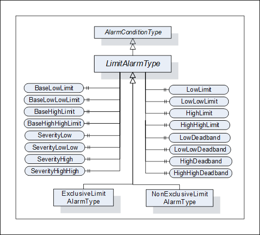
Figure 18 – LimitAlarmType
The LimitAlarmType is formally defined in Table 92.
Table 92 – LimitAlarmType definition
|
Attribute |
Value |
||||
|
BrowseName |
LimitAlarmType |
||||
|
IsAbstract |
False |
||||
|
References |
NodeClass |
BrowseName |
DataType |
TypeDefinition |
Modelling |
|
Subtype of the AlarmConditionType defined in clause 5.8.2. |
|||||
|
HasSubtype |
ObjectType |
ExclusiveLimitAlarmType |
Defined in Clause 5.8.19.3 |
||
|
HasSubtype |
ObjectType |
NonExclusiveLimitAlarmType |
Defined in Clause 5.8.20 |
||
|
HasProperty |
Variable |
HighHighLimit |
Double |
PropertyType |
Optional |
|
HasProperty |
Variable |
HighLimit |
Double |
PropertyType |
Optional |
|
HasProperty |
Variable |
LowLimit |
Double |
PropertyType |
Optional |
|
HasProperty |
Variable |
LowLowLimit |
Double |
PropertyType |
Optional |
|
HasProperty |
Variable |
BaseHighHighLimit |
Double |
PropertyType |
Optional |
|
HasProperty |
Variable |
BaseHighLimit |
Double |
PropertyType |
Optional |
|
HasProperty |
Variable |
BaseLowLimit |
Double |
PropertyType |
Optional |
|
HasProperty |
Variable |
BaseLowLowLimit |
Double |
PropertyType |
Optional |
|
HasProperty |
Variable |
SeverityHighHigh |
UInt16 |
PropertyType |
Optional |
|
HasProperty |
Variable |
SeverityHigh |
UInt16 |
PropertyType |
Optional |
|
HasProperty |
Variable |
SeverityLow |
UInt16 |
PropertyType |
Optional |
|
HasProperty |
Variable |
SeverityLowLow |
UInt16 |
PropertyType |
Optional |
|
HasProperty |
Variable |
HighHighDeadband |
Double |
PropertyType |
Optional |
|
HasProperty |
Variable |
HighDeadband |
Double |
PropertyType |
Optional |
|
HasProperty |
Variable |
LowDeadband |
Double |
PropertyType |
Optional |
|
HasProperty |
Variable |
LowLowDeadband |
Double |
PropertyType |
Optional |
|
ConformanceUnits |
|||||
|
A & C Exclusive Limit |
|||||
|
A & C Non-Exclusive Limit |
|||||
Four optional limits are defined that configure the states of the derived limit Alarm Types. These Properties shall be set for any Alarm limits that are exposed by the derived limit Alarm types. These Properties are listed as optional but at least one is required. For cases where an underlying system cannot provide the actual value of a limit, the limit Property shall still be provided, but will have its AccessLevel set to not readable. It is assumed that the limits are described using the same Engineering Unit that is assigned to the variable that is the source of the Alarm. For Rate of change limit Alarms, it is assumed this rate is units per second unless otherwise specified. The limits shall follow the following inequality HighHigh > High > Low > LowLow. If Deadband properties are provided then:
· HighHighLimit - HighHighDeadband > HighLimit
· HighLimit – HighDeadband > LowLimit
· LowLimit + LowDeadband < HighLimit
· LowLowLimit + LowLowDeadband < LowLimit
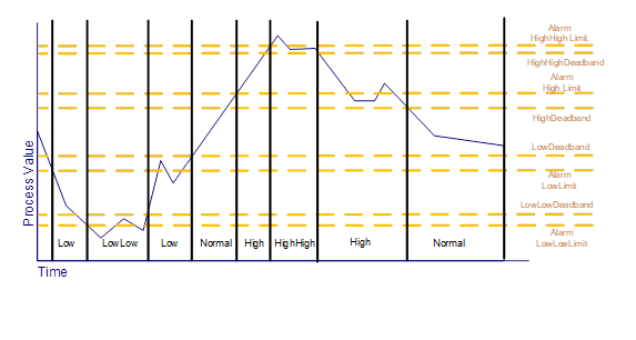
Four optional base limits are defined that are used for AdaptiveAlarming. They contain the configured Alarm limit. If a Server supports AdaptiveAlarming for Alarm limits, the corresponding base Alarm limit shall be provided for any limits that are exposed by the derived limit Alarm types. The value of this property is the value of the limit to which an AdaptiveAlarm can be reset if any algorithmic changes need to be discarded.
The Alarm limits listed may cause an Alarm to be generated when a value equals the limit or it may generate the Alarm when the limit is exceeded, (i.e. the Value is above the limit for HighLimit and below the limit for LowLimit). The exact behaviour when the value is equal to the limit is Server specific.
· if any element of the array exceeds the limit an Alarm is generated,
· if all elements exceed the limit an Alarm is generated,
· the limits may also be an array, in which case if any array limit is exceeded by the corresponding source array element, an Alarm is generated.
The four optional severity Properties, if defined, provided the severity for each of the limits.
The four optional deadband Properties, if they are defined, are used to delay the return to normal until the value is within the limit by the value of the deadband. For example, if a Value exceeds a HighLimit of 20, and there is a HighDeadband define of 1, the value will remain in alarm until the Value drops below 19. An Alarm deadband can be used to limit Alarms in a system where values may bounce or have some noise (i.e. the value is jumping up and down by 0.2). They keep the Alarm from being reactivated until it has dropped enough to not retrigger by noise.
In the event of a restart of an AlarmManager, the AlarmManager shall recover the LimitAlarm state, this also applies to all subtypes.
This clause describes the state machine and the base Alarm Type behaviour for AlarmConditionTypes with multiple mutually exclusive limits.
The ExclusiveLimitStateMachineType defines the state machine used by AlarmConditionTypes that handle multiple mutually exclusive limits. It is illustrated in Figure 19.
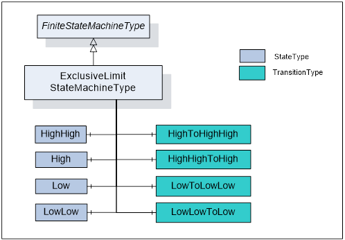
Figure 19 – ExclusiveLimitStateMachineType
It is created by extending the FiniteStateMachineType. It is formally defined in Table 93 and the state transitions are described in Table 94.
Table 93 – ExclusiveLimitStateMachineType definition
|
Attribute |
Value |
||||
|
BrowseName |
ExclusiveLimitStateMachineType |
||||
|
IsAbstract |
False |
||||
|
References |
NodeClass |
BrowseName |
DataType |
TypeDefinition |
ModellingRule |
|
Subtype of the FiniteStateMachineType |
|||||
|
HasComponent |
Object |
HighHigh |
|
StateType |
|
|
HasComponent |
Object |
High |
|
StateType |
|
|
HasComponent |
Object |
Low |
|
StateType |
|
|
HasComponent |
Object |
LowLow |
|
StateType |
|
|
HasComponent |
Object |
LowToLowLow |
|
TransitionType |
|
|
HasComponent |
Object |
LowLowToLow |
|
TransitionType |
|
|
HasComponent |
Object |
HighToHighHigh |
|
TransitionType |
|
|
HasComponent |
Object |
HighHighToHigh |
|
TransitionType |
|
|
ConformanceUnits |
|||||
|
A & C Exclusive Limit |
|||||
Table 94 – ExclusiveLimitStateMachineType Additional References
|
SourceBrowsePath |
References |
IsForward |
TargetBrowsePath |
|
HighHighToHigh |
FromState |
True |
HighHigh |
|
ToState |
True |
High |
|
|
HasEffect |
True |
AlarmConditionType |
|
|
HighToHighHigh |
FromState |
True |
High |
|
ToState |
True |
HighHigh |
|
|
HasEffect |
True |
AlarmConditionType |
|
|
LowLowToLow |
FromState |
True |
LowLow |
|
ToState |
True |
Low |
|
|
HasEffect |
True |
AlarmConditionType |
|
|
LowToLowLow |
FromState |
True |
Low |
|
ToState |
True |
LowLow |
|
|
HasEffect |
True |
AlarmConditionType |
‘
The component Variables of the ExclusiveLimitStateMachineType have additional Attributes defined in Table 95.
Table 95 – ExclusiveLimitStateMachineType Attribute values for child Nodes
|
BrowsePath |
Value Attribute |
||
|
1 |
||
|
2 |
||
|
3 |
||
|
4 |
||
|
34 |
||
|
43 |
||
|
21 |
||
|
12 |
The ExclusiveLimitStateMachineType defines the sub state machine that represents the actual level of a multilevel Alarm when it is in the Active state. The sub state machine defined here includes High, Low, HighHigh and LowLow states. This model also includes in its transition state a series of transition to and from a parent state, the inactive state. This state machine as it is defined shall be used as a sub state machine for a state machine which has an Active state. This Active state could be part of a “level” Alarm or “deviation” Alarm or any other Alarm state machine.
The LowLow, Low, High, HighHigh are typical for many industries. Vendors can introduce sub-state models that include additional limits; they may also omit limits in an instance. If a model omits states or transitions in the StateMachine, it is recommended that they provide the optional Property AvailableStates and/or AvailableTransitions (see 10000-16).
The ExclusiveLimitAlarmType is used to specify the common behaviour for Alarm Types with multiple mutually exclusive limits. The ExclusiveLimitAlarmType is illustrated in Figure 20.
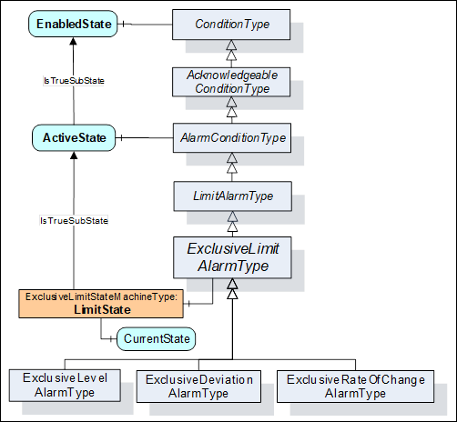
Figure 20 – ExclusiveLimitAlarmType
The ExclusiveLimitAlarmType is formally defined in Table 96.
Table 96 – ExclusiveLimitAlarmType definition
|
Attribute |
Value |
||||
|
BrowseName |
ExclusiveLimitAlarmType |
||||
|
IsAbstract |
False |
||||
|
References |
NodeClass |
BrowseName |
DataType |
TypeDefinition |
Modelling |
|
Subtype of the LimitAlarmType defined in clause 5.8.18. |
|||||
|
HasSubtype |
ObjectType |
ExclusiveLevelAlarmType |
Defined in Clause 5.8.21.3 |
||
|
HasSubtype |
ObjectType |
ExclusiveDeviationAlarmType |
Defined in Clause 5.8.22.3 |
||
|
HasSubtype |
ObjectType |
ExclusiveRateOfChangeAlarmType |
Defined in Clause 5.8.23.3 |
||
|
HasComponent |
Object |
LimitState |
|
ExclusiveLimitStateMachineType |
Mandatory |
|
ConformanceUnits |
|||||
|
A & C Exclusive Limit |
|||||
The LimitState is a sub state of the ActiveState and has an IsTrueSubStateOf reference to the ActiveState. The LimitState represents the actual limit that is violated in an instance of ExclusiveLimitAlarmType. When the ActiveState of the AlarmConditionType is inactive the LimitState shall not be available and shall return NULL on read. Any Events that subscribe for fields from the LimitState when the ActiveState is inactive shall return a NULL for these unavailable fields.
The NonExclusiveLimitAlarmType is used to specify the common behaviour for Alarm Types with multiple non-exclusive limits. The NonExclusiveLimitAlarmType is illustrated in Figure 21.
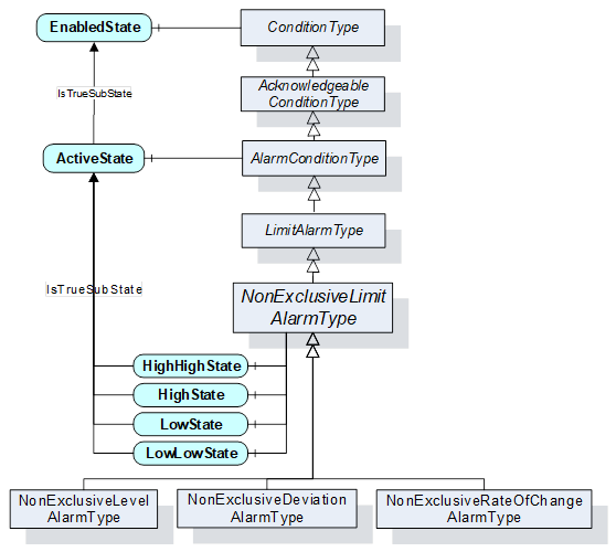
Figure 21 – NonExclusiveLimitAlarmType
The NonExclusiveLimitAlarmType is formally defined in Table 97 and Table 98.
Table 97 – NonExclusiveLimitAlarmType definition
|
Attribute |
Value |
||||
|
BrowseName |
NonExclusiveLimitAlarmType |
||||
|
IsAbstract |
False |
||||
|
References |
NodeClass |
BrowseName |
DataType |
TypeDefinition |
Modelling |
|
Subtype of the LimitAlarmType defined in clause 5.8.18. |
|||||
|
HasSubtype |
ObjectType |
NonExclusiveLevelAlarmType |
Defined in Clause 5.8.21.2 |
||
|
HasSubtype |
ObjectType |
NonExclusiveDeviationAlarmType |
Defined in Clause 5.8.22.2 |
||
|
HasSubtype |
ObjectType |
NonExclusiveRateOfChangeAlarmType |
Defined in Clause 5.8.23.2 |
||
|
HasComponent |
Variable |
HighHighState |
LocalizedText |
TwoStateVariableType |
Optional |
|
HasComponent |
Variable |
HighState |
LocalizedText |
TwoStateVariableType |
Optional |
|
HasComponent |
Variable |
LowState |
LocalizedText |
TwoStateVariableType |
Optional |
|
HasComponent |
Variable |
LowLowState |
LocalizedText |
TwoStateVariableType |
Optional |
|
|
|||||
|
ConformanceUnits |
|||||
|
A & C Non-Exclusive Limit |
|||||
Table 98 – NonExclusiveLimitAlarmType Additional Subcomponents
|
BrowsePath |
References |
NodeClass |
BrowseName |
DataType |
TypeDefinition |
Others |
|
HighHighState |
HasProperty |
Variable |
TrueState |
LocalizedText |
PropertyType |
|
|
HighHighState |
HasProperty |
Variable |
FalseState |
LocalizedText |
PropertyType |
|
|
HighState |
HasProperty |
Variable |
TrueState |
LocalizedText |
PropertyType |
|
|
HighState |
HasProperty |
Variable |
FalseState |
LocalizedText |
PropertyType |
|
|
LowState |
HasProperty |
Variable |
TrueState |
LocalizedText |
PropertyType |
|
|
LowState |
HasProperty |
Variable |
FalseState |
LocalizedText |
PropertyType |
|
|
LowLowState |
HasProperty |
Variable |
TrueState |
LocalizedText |
PropertyType |
|
|
LowLowState |
HasProperty |
Variable |
FalseState |
LocalizedText |
PropertyType |
|
The empty “Others” column indicates that no ModellingRule applies.
HighHighState, HighState, LowState, and LowLowState represent the non-exclusive states. As an example, it is possible that both HighState and HighHighState are in their True state. Vendors may choose to support any subset of these states. Recommended state names are described in A.1.
Four optional limits are defined that configure these states. At least the HighState or the LowState shall be provided even though all states are optional. It is implied by the definition of a HighState and a LowState, that these groupings are mutually exclusive. A value cannot exceed both a HighState value and a LowState value simultaneously.
A level Alarm is commonly used to report when a limit is exceeded. It typically relates to an instrument – e.g. a temperature meter. The level Alarm becomes active when the observed value is above a high limit or below a low limit.
The NonExclusiveLevelAlarmType is a special level Alarm utilized with one or more non-exclusive states. If for example both the High and HighHigh states need to be maintained as active at the same time then an instance of NonExclusiveLevelAlarmType should be used.
The NonExclusiveLevelAlarmType is based on the NonExclusiveLimitAlarmType. It is formally defined in Table 99.
Table 99 – NonExclusiveLevelAlarmType definition
|
Attribute |
Value |
||||
|
BrowseName |
NonExclusiveLevelAlarmType |
||||
|
IsAbstract |
False |
||||
|
References |
NodeClass |
BrowseName |
DataType |
TypeDefinition |
ModellingRule |
|
Subtype of the NonExclusiveLimitAlarmType defined in clause 5.8.20. |
|||||
|
|
|
|
|
|
|
|
ConformanceUnits |
|||||
|
A & C Non-Exclusive Level |
|||||
No additional Properties to the NonExclusiveLimitAlarmType are defined.
The ExclusiveLevelAlarmType is a special level Alarm utilized with multiple mutually exclusive limits. It is formally defined in Table 100.
Table 100 – ExclusiveLevelAlarmType definition
|
Attribute |
Value |
||||
|
BrowseName |
ExclusiveLevelAlarmType |
||||
|
IsAbstract |
False |
||||
|
References |
NodeClass |
BrowseName |
DataType |
TypeDefinition |
ModellingRule |
|
Inherits the Properties of the ExclusiveLimitAlarmType defined in clause 5.8.19.3. |
|||||
|
|
|
|
|
|
|
|
ConformanceUnits |
|||||
|
A & C Exclusive Level |
|||||
No additional Properties to the ExclusiveLimitAlarmType are defined.
A deviation Alarm is commonly used to report an excess deviation between a desired set point level of a process value and an actual measurement of that value. The deviation Alarm becomes active when the deviation exceeds or drops below a defined limit.
For example, if a set point had a value of 10, a high deviation Alarm limit of 2 and a low deviation Alarm limit of -1 then the low sub state is entered if the process value drops below 9; the high sub state is entered if the process value raises above 12. If the set point were changed to 11 then the new deviation values would be 10 and 13 respectively. The set point can be fixed by a configuration, adjusted by an Operator or it can be adjusted by an algorithm, the actual functionality exposed by the set point is application specific. The deviation Alarm can also be used to report a problem between a redundant data source where the difference between the primary source and the secondary source exceeds the included limit. In this case, the SetpointNode would point to the secondary source.
The LowLimit and LowLowLimit shall be negative, indicating a number below the target value and the HighLimit and HighHighLimit shall be positive, indicating a number above the target value. If provided, the limits shall not be zero and shall follow these rules:
· HighHighLimit > HighLimit
· LowLimit > LowLowLimit.
For example, if the LowLimit is -2 then a LowLowLimit of -1 would not be allowed, but a LowLowLimit of -3 would be allowed.
The NonExclusiveDeviationAlarmType is a special level Alarm utilized with one or more non-exclusive states. If for example both the High and HighHigh states need to be maintained as active at the same time then an instance of NonExclusiveDeviationAlarmType should be used.
The NonExclusiveDeviationAlarmType is based on the NonExclusiveLimitAlarmType. It is formally defined in Table 101.
Table 101 – NonExclusiveDeviationAlarmType definition
|
Attribute |
Value |
||||
|
BrowseName |
NonExclusiveDeviationAlarmType |
||||
|
IsAbstract |
False |
||||
|
References |
NodeClass |
BrowseName |
DataType |
TypeDefinition |
ModellingRule |
|
Subtype of the NonExclusiveLimitAlarmType defined in clause 5.8.20. |
|||||
|
HasProperty |
Variable |
SetpointNode |
NodeId |
PropertyType |
Mandatory |
|
HasProperty |
Variable |
BaseSetpointNode |
NodeId |
PropertyType |
Optional |
|
|
|||||
|
ConformanceUnits |
|||||
|
A & C Non-Exclusive Deviation |
|||||
The SetpointNode Property provides the NodeId of the set point used in the deviation calculation. In cases where the Alarm is generated by an underlying system and if the Variable is not in the AddressSpace, a NULL NodeId shall be provided.
The BaseSetpointNode Property provides the NodeId of the original or base setpoint. The value of this node is the value of the setpoint to which an AdaptiveAlarm can be reset if any algorithmic changes need to be discarded. The value of this node usually contains the originally configured set point.
The ExclusiveDeviationAlarmType is utilized with multiple mutually exclusive limits. It is formally defined in Table 102.
Table 102 – ExclusiveDeviationAlarmType definition
|
Attribute |
Value |
||||
|
BrowseName |
ExclusiveDeviationAlarmType |
||||
|
IsAbstract |
False |
||||
|
References |
NodeClass |
BrowseName |
DataType |
TypeDefinition |
Modelling Rule |
|
Inherits the Properties of the ExclusiveLimitAlarmType defined in clause 5.8.19.3. |
|||||
|
HasProperty |
Variable |
SetpointNode |
NodeId |
PropertyType |
Mandatory |
|
HasProperty |
Variable |
BaseSetpointNode |
NodeId |
PropertyType |
Optional |
|
|
|||||
|
ConformanceUnits |
|||||
|
A & C Exclusive Deviation |
|||||
The SetpointNode Property provides the NodeId of the set point used in the Deviation calculation. If this Variable is not in the AddressSpace, a NULL NodeId shall be provided.
The BaseSetpointNode Property provides the NodeId of the original or base setpoint. The value of this node is the value of the set point to which an AdaptiveAlarm can be reset if any algorithmic changes need to be discarded. The value of this node usually contains the originally configured set point.
A Rate of Change Alarm is commonly used to report an unusual change or lack of change in a measured value related to the speed at which the value has changed. The Rate of Change Alarm becomes active when the rate at which the value changes exceeds or drops below a defined limit.
A Rate of Change is measured in some time unit, such as seconds or minutes and some unit of measure such as percent or meter. For example, a tank may have a High limit for the Rate of Change of its level (measured in meters) which would be 4 meters per minute. If the tank level changes at a rate that is greater than 4 meters per minute then the High sub state is entered.
The NonExclusiveRateOfChangeAlarmType is a special level Alarm utilized with one or more non-exclusive states. If for example both the High and HighHigh states need to be maintained as active at the same time this AlarmConditionType should be used
The NonExclusiveRateOfChangeAlarmType is based on the NonExclusiveLimitAlarmType. It is formally defined in Table 103.
Table 103 – NonExclusiveRateOfChangeAlarmType definition
|
Attribute |
Value |
||||
|
BrowseName |
NonExclusiveRateOfChangeAlarmType |
||||
|
IsAbstract |
False |
||||
|
References |
NodeClass |
BrowseName |
DataType |
TypeDefinition |
ModellingRule |
|
Subtype of the NonExclusiveLimitAlarmType defined in clause 5.8.20. |
|||||
|
HasProperty |
Variable |
EngineeringUnits |
EUInformation |
PropertyType |
Optional |
|
|
|||||
|
ConformanceUnits |
|||||
|
A & C Non-Exclusive RateOfChange |
|||||
EngineeringUnits provides the engineering units associated with the limits values. If this is not provided the assumed Engineering Unit is the same as the EU associated with the parent variable per second e.g. if parent is meters, this unit is meters/second.
ExclusiveRateOfChangeAlarmType is utilized with multiple mutually exclusive limits. It is formally defined in Table 104.
Table 104 – ExclusiveRateOfChangeAlarmType definition
|
Attribute |
Value |
||||
|
BrowseName |
ExclusiveRateOfChangeAlarmType |
||||
|
IsAbstract |
False |
||||
|
References |
NodeClass |
BrowseName |
DataType |
TypeDefinition |
ModellingRule |
|
Inherits the Properties of the ExclusiveLimitAlarmType defined in clause 5.8.19.3. |
|||||
|
HasProperty |
Variable |
EngineeringUnits |
EUInformation |
PropertyType |
Optional |
|
|
|||||
|
ConformanceUnits |
|||||
|
A & C Exclusive RateOfChange |
|||||
EngineeringUnits provides the engineering units associated with the limits values. If this is not provided the assumed Engineering Unit is the same as the EU associated with the parent variable per second e.g. if parent is meters, this unit is meters/second.
The DiscreteAlarmType is used to classify Types into Alarm Conditions where the input for the Alarm may take on only a certain number of possible values (e.g. True/False, running/stopped/terminating). The DiscreteAlarmType with sub types defined in this standard is illustrated in Figure 22. It is formally defined in Table 105.
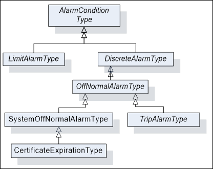
Figure 22 – DiscreteAlarmType Hierarchy
Table 105 – DiscreteAlarmType definition
|
Attribute |
Value |
||||
|
BrowseName |
DiscreteAlarmType |
||||
|
IsAbstract |
False |
||||
|
References |
NodeClass |
BrowseName |
DataType |
TypeDefinition |
Modelling |
|
Subtype of the AlarmConditionType defined in clause 5.8.2. |
|||||
|
HasSubtype |
ObjectType |
OffNormalAlarmType |
Defined in Clause 5.8.22 |
||
|
ConformanceUnits |
|||||
|
A & C Discrete |
|||||
The OffNormalAlarmType is a specialization of the DiscreteAlarmType intended to represent a discrete Condition that is considered to be not normal. It is formally defined in Table 106. This sub type is usually used to indicate that a discrete value is in an Alarm state, it is active as long as a non-normal value is present.
Table 106 – OffNormalAlarmType definition
|
Attribute |
Value |
|||||
|
BrowseName |
OffNormalAlarmType |
|||||
|
IsAbstract |
False |
|||||
|
References |
NodeClass |
BrowseName |
DataType |
TypeDefinition |
ModellingRule |
|
|
Subtype of the DiscreteAlarmType defined in clause 5.8.24.1 |
||||||
|
HasSubtype |
ObjectType |
TripAlarmType |
Defined in Clause 5.8.24.4 |
|||
|
HasSubtype |
ObjectType |
SystemOffNormalAlarmType |
Defined in Clause 5.8.24.3 |
|||
|
|
|
|
|
|||
|
HasProperty |
Variable |
NormalState |
NodeId |
PropertyType |
Mandatory |
|
|
ConformanceUnits |
||||||
|
A & C OffNormal |
||||||
The NormalState Property is a Property that points to a Variable which has a value that corresponds to one of the possible values of the Variable pointed to by the InputNode Property where the NormalState Property Variable value is the value that is considered to be the normal state of the Variable pointed to by the InputNode Property. When the value of the Variable referenced by the InputNode Property is not equal to the value of the NormalState Property the Alarm is Active. If this Variable is not in the AddressSpace, a NULL NodeId shall be provided.
This Condition is used by a Server to indicate that an underlying system that is providing Alarm information is having a communication problem and that the Server may have invalid or incomplete Condition state in the Subscription. Its representation in the AddressSpace is formally defined in Table 107.
Table 107 – SystemOffNormalAlarmType definition
|
Attribute |
Value |
||||
|
BrowseName |
SystemOffNormalAlarmType |
||||
|
IsAbstract |
False |
||||
|
References |
NodeClass |
BrowseName |
DataType |
TypeDefinition |
ModellingRule |
|
HasSubtype |
ObjectType |
CertificateExpirationAlarmType |
Defined in Clause 5.8.24.7 |
||
|
Subtype of the OffNormalAlarmType, i.e. it has HasProperty References to the same Nodes. |
|||||
|
ConformanceUnits |
|||||
|
A & C SystemOffNormal |
|||||
The TripAlarmType is a specialization of the OffNormalAlarmType intended to represent an equipment trip Condition. The Alarm becomes active when the monitored piece of equipment experiences some abnormal fault such as a motor shutting down due to an overload condition. It is formally defined in Table 108. This Type is mainly used for categorization.
Table 108 – TripAlarmType definition
|
Attribute |
Value |
||||
|
BrowseName |
TripAlarmType |
||||
|
IsAbstract |
False |
||||
|
References |
NodeClass |
BrowseName |
DataType |
TypeDefinition |
Modelling |
|
Subtype of the OffNormalAlarmType defined in clause 5.8.24.2. |
|||||
|
|
|
|
|
||
|
A & C Trip |
|||||
The InstrumentDiagnosticAlarmType is a specialization of the OffNormalAlarmType intended to represent a fault in a field device. The Alarm becomes active when the monitored device experiences a fault such as a sensor failure. It is formally defined in Table 108. This Type is mainly used for categorization.
Table 109 – InstrumentDiagnosticAlarmType definition
|
Attribute |
Value |
||||
|
BrowseName |
InstrumentDiagnosticAlarmType |
||||
|
IsAbstract |
False |
||||
|
References |
NodeClass |
BrowseName |
DataType |
TypeDefinition |
Modelling |
|
Subtype of the OffNormalAlarmType defined in clause 5.8.24.2. |
|||||
|
|
|
|
|
||
|
ConformanceUnits |
|||||
|
A & C InstrumentDiagnostic |
|||||
The SystemDiagnosticAlarmType is a specialization of the OffNormalAlarmType intended to represent a fault in a system or sub-system. The Alarm becomes active when the monitored system experiences a fault. It is formally defined in Table 108. This Type is mainly used for categorization.
Table 110 – SystemDiagnosticAlarmType definition
|
Attribute |
Value |
||||
|
BrowseName |
SystemDiagnosticAlarmType |
||||
|
IsAbstract |
False |
||||
|
References |
NodeClass |
BrowseName |
DataType |
TypeDefinition |
Modelling |
|
Subtype of the OffNormalAlarmType defined in clause 5.8.24.2. |
|||||
|
|
|
|
|
||
|
ConformanceUnits |
|||||
|
A & C SystemDiagnostic |
|||||
This SystemOffNormalAlarmType is raised by the Server when the Server’s Certificate is within the ExpirationLimit of expiration. This Alarm automatically returns to normal when the certificate is updated.
Table 111 – CertificateExpirationAlarmType definition
|
Attribute |
Value |
||||
|
BrowseName |
CertificateExpirationAlarmType |
||||
|
IsAbstract |
False |
||||
|
References |
NodeClass |
BrowseName |
DataType |
TypeDefinition |
ModellingRule |
|
Subtype of the SystemOffNormalAlarmType defined in clause 5.8.24.3 |
|||||
|
HasProperty |
Variable |
ExpirationDate |
DateTime |
PropertyType |
Mandatory |
|
HasProperty |
Variable |
ExpirationLimit |
Duration |
PropertyType |
Optional |
|
HasProperty |
Variable |
CertificateType |
NodeId |
PropertyType |
Mandatory |
|
HasProperty |
Variable |
Certificate |
ByteString |
PropertyType |
Mandatory |
|
ConformanceUnits |
|||||
|
A & C CertificateExpiration |
|||||
ExpirationDate is the date and time this certificate will expire.
ExpirationLimit is the time interval before the ExpirationDate at which this Alarm will trigger. This shall be a positive number. If the property is not provided, a default of 2 weeks shall be used.
CertificateType – See Part 12 for definition of CertificateType.
Certificate is the certificate that is about to expire.
The DiscrepancyAlarmType is commonly used to report an action that did not occur within an expected time range.
The DiscrepancyAlarmType is based on the AlarmConditionType. It is formally defined in Table 112.
Table 112 – DiscrepancyAlarmType definition
|
Attribute |
Value |
||||
|
BrowseName |
DiscrepancyAlarmType |
||||
|
IsAbstract |
False |
||||
|
References |
Node Class |
BrowseName |
DataType |
TypeDefinition |
ModellingRule |
|
Subtype of the AlarmConditionType defined in 5.8.2. |
|||||
|
HasProperty |
Variable |
TargetValueNode |
NodeId |
PropertyType |
Mandatory |
|
HasProperty |
Variable |
ExpectedTime |
Duration |
PropertyType |
Mandatory |
|
HasProperty |
Variable |
Tolerance |
Double |
PropertyType |
Optional |
|
ConformanceUnits |
|||||
|
A & C Discrepancy |
|||||
The TargetValueNode Property provides the NodeId of the Variable that is used for the target value.
The ExpectedTime Property provides the Duration within which the value pointed to by the InputNode shall equal the value specified by the TargetValueNode (or be within the Tolerance range, if specified).
The Tolerance Property is a value that can be added to or subtracted from the TargetValueNode’s value, providing a range that the value can be in without generating the Alarm.
A DiscrepancyAlarmType can be used to indicate a motor has not responded to a start request within a given time, or that a process value has not reached a given value after a setpoint change within a given time interval.
The DiscrepancyAlarmType shall return to normal when the value has reached the target value.
Conditions are used in specific application domains like Maintenance, System or Process. The ConditionClass hierarchy is used to specify domains and is orthogonal to the ConditionType hierarchy. The ConditionClassId Property of the ConditionType is used to assign a Condition to a ConditionClass. Clients can use this Property to filter out essential classes. OPC UA defines the base ObjectType for all ConditionClasses and a set of common classes used across many industries. Figure 23 informally describes the hierarchy of ConditionClass Types defined in this standard.
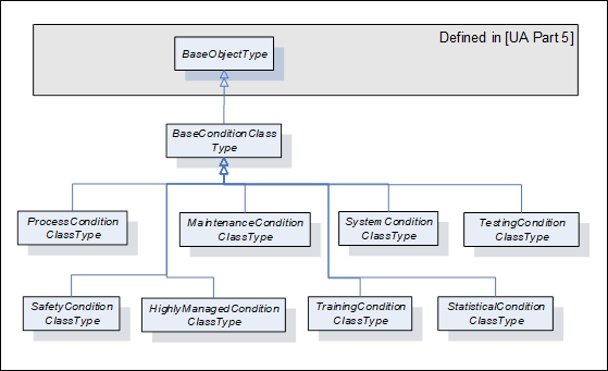
Figure 23 – ConditionClass type hierarchy
ConditionClasses are not representations of Objects in the underlying system and, therefore, only exist as Type Nodes in the Address Space.
BaseConditionClassType is used as class whenever a Condition cannot be assigned to a more concrete class. Servers should use a more specific ConditionClass, if possible. All ConditionClass Types derive from BaseConditionClassType. It is formally defined in Table 113.
Table 113 – BaseConditionClassType definition
|
Attribute |
Value |
||||
|
BrowseName |
BaseConditionClassType |
||||
|
IsAbstract |
True |
||||
|
References |
NodeClass |
BrowseName |
DataType |
TypeDefinition |
ModellingRule |
|
Subtype of the BaseObjectType defined in 10000-5. |
|||||
|
|
|
|
|
||
|
ConformanceUnits |
|||||
|
A & C ConditionClasses |
|||||
The ProcessConditionClassType is used to classify Conditions related to the process itself. Examples of a process would be a control system in a boiler or the instrumentation associated with a chemical plant or paper machine. The ProcessConditionClassType is formally defined in Table 114.
Table 114 – ProcessConditionClassType definition
|
Attribute |
Value |
||||
|
BrowseName |
ProcessConditionClassType |
||||
|
IsAbstract |
True |
||||
|
References |
NodeClass |
BrowseName |
DataType |
TypeDefinition |
Modelling |
|
Subtype of the BaseConditionClassType defined in clause 5.9.2. |
|||||
|
|
|
|
|
||
|
ConformanceUnits |
|||||
|
A & C ConditionClasses |
|||||
The MaintenanceConditionClassType is used to classify Conditions related to maintenance. Examples of maintenance would be Asset Management systems or conditions, which occur in process control systems, which are related to calibration of equipment. The MaintenanceConditionClassType is formally defined in Table 115. No further definition is provided here. It is expected that other standards groups will define domain-specific sub-types.
Table 115 – MaintenanceConditionClassType definition
|
Attribute |
Value |
||||
|
BrowseName |
MaintenanceConditionClassType |
||||
|
IsAbstract |
True |
||||
|
References |
NodeClass |
BrowseName |
DataType |
TypeDefinition |
ModellingRule |
|
Subtype of the BaseConditionClassType defined in clause 5.9.2. |
|||||
|
|
|
|
|
||
|
ConformanceUnits |
|||||
|
A & C ConditionClasses |
|||||
The SystemConditionClassType is used to classify Conditions related to the System. It is formally defined in Table 116. System Conditions occur in the controlling or monitoring system process. Examples of System related items could include available disk space on a computer, Archive media availability, network loading issues or a controller error. It is expected that other standards groups or vendors will define domain-specific sub-types.
Table 116 – SystemConditionClassType definition
|
Attribute |
Value |
||||
|
BrowseName |
SystemConditionClassType |
||||
|
IsAbstract |
True |
||||
|
References |
NodeClass |
BrowseName |
DataType |
TypeDefinition |
ModellingRule |
|
Subtype of the BaseConditionClassType defined in clause 5.9.2. |
|||||
|
|
|
|
|
||
|
A & C ConditionClasses |
|||||
The SafetyConditionClassType is used to classify Conditions related to safety. It is formally defined in Table 117.
Safety Conditions occur in the controlling or monitoring system process. Examples of safety related items could include, emergency shutdown systems or fire suppression systems.
Table 117 – SafetyConditionClassType definition
|
Attribute |
Value |
||||
|
BrowseName |
SafetyConditionClassType |
||||
|
IsAbstract |
True |
||||
|
References |
NodeClass |
BrowseName |
DataType |
TypeDefinition |
ModellingRule |
|
Subtype of the BaseConditionClassType defined in clause 5.9.2. |
|||||
|
|
|
|
|
||
|
ConformanceUnits |
|||||
|
A & C ConditionClasses |
|||||
In Alarm systems some Alarms may be classified as highly managed Alarms. This class of Alarm requires special handling that varies according to the individual requirements. It might require individual acknowledgement or not allow suppression or any of a number of other special behaviours. The HighlyManagedAlarmConditionClassType is used to classify Conditions as highly managed Alarms. It is formally defined in Table 118.
Table 118 – HighlyManagedAlarmConditionClassType definition
|
Attribute |
Value |
||||
|
BrowseName |
HighlyManagedAlarmConditionClassType |
||||
|
IsAbstract |
True |
||||
|
References |
NodeClass |
BrowseName |
DataType |
TypeDefinition |
ModellingRule |
|
Subtype of the BaseConditionClassType defined in clause 5.9.2. |
|||||
|
|
|
|
|
||
|
ConformanceUnits |
|||||
|
A & C ConditionClasses |
|||||
The TrainingConditionClassType is used to classify Conditions related to training system or training exercises. It is formally defined in Table 119. These Conditions typically occur in a training system or are generated as part of a simulation for a training exercise. Training Conditions might be process or system conditions. It is expected that other standards groups or vendors will define domain-specific sub-types.
Table 119 – TrainingConditionClassType definition
|
Attribute |
Value |
||||
|
BrowseName |
TrainingConditionClassType |
||||
|
IsAbstract |
True |
||||
|
References |
NodeClass |
BrowseName |
DataType |
TypeDefinition |
ModellingRule |
|
Subtype of the BaseConditionClassType defined in clause. |
|||||
|
|
|
|
|
||
|
ConformanceUnits |
|||||
|
A & C ConditionClasses |
|||||
The StatisticalConditionClassType is used to classify Conditions related that are based on statistical calculations. It is formally defined in Table 120. These Conditions are generated as part of a statistical analysis. They might be any of an Alarm number of types.
Table 120 – StatisticalConditionClassType definition
|
Attribute |
Value |
||||
|
BrowseName |
StatisticalConditionClassType |
||||
|
IsAbstract |
True |
||||
|
References |
NodeClass |
BrowseName |
DataType |
TypeDefinition |
ModellingRule |
|
Subtype of the BaseConditionClassType defined in clause. |
|||||
|
|
|
|
|
||
|
ConformanceUnits |
|||||
|
A & C ConditionClasses |
|||||
The TestingConditionClassType is used to classify Conditions related to testing of an Alarm system or Alarm function. It is formally defined in Table 121. Testing Conditions might include a condition to test an alarm annunciation such as a horn or other panel. It might also be used to temporarily reclassify a Condition to check response times or suppression logic. It is expected that other standards groups or vendors will define domain-specific sub-types.
Table 121 – TestingConditionClassType definition
|
Attribute |
Value |
||||
|
BrowseName |
TestingConditionClassType |
||||
|
IsAbstract |
True |
||||
|
References |
NodeClass |
BrowseName |
DataType |
TypeDefinition |
ModellingRule |
|
Subtype of the BaseConditionClassType defined in clause 5.9.2. |
|||||
|
|
|
|
|
||
|
ConformanceUnits |
|||||
|
A & C ConditionClasses |
|||||
If Auditing is supported by a Server, Events of AuditConditionEventType shall be generated. Following are the sub-types of AuditUpdateMethodEventType that will be generated in response to the Methods defined in this document. They are illustrated in Figure 24.
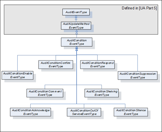
Figure 24 – AuditEvent hierarchy
AuditConditionEventTypes are normally used in response to a Method call. However, these Events shall also be notified if the functionality of such a Method is performed by some other Server-specific means. In this case, the SourceName Property shall contain a proper description of this internal means and the other Properties should be filled in as described for the given EventType.
This EventType is used to subsume all AuditConditionEventTypes. It is formally defined in Table 122.
Table 122 – AuditConditionEventType definition
|
Attribute |
Value |
|||||
|
BrowseName |
AuditConditionEventType |
|||||
|
IsAbstract |
False |
|||||
|
References |
NodeClass |
BrowseName |
DataType |
TypeDefinition |
ModellingRule |
|
|
Subtype of the AuditUpdateMethodEventType defined in 10000-5 |
||||||
|
ConformanceUnits |
||||||
|
A & C Auditing |
||||||
AuditConditionEventTypes inherit all Properties of the AuditUpdateMethodEventType defined in 10000-5. Unless a subtype overrides the definition, the inherited Properties of the Condition will be used as defined.
· The inherited Property SourceNode shall be filled with the ConditionId.
· The SourceName shall be “Method/” and the name of the Service that generated the Event (e.g. Disable, Enable, Acknowledge, etc.).
This EventType can be further customized to reflect particular Condition related actions.
This EventType is used to indicate a change in the enabled state of a Condition instance. It is formally defined in Table 123.
Table 123 – AuditConditionEnableEventType definition
|
Attribute |
Value |
|||||
|
BrowseName |
AuditConditionEnableEventType |
|||||
|
IsAbstract |
False |
|||||
|
References |
NodeClass |
BrowseName |
DataType |
TypeDefinition |
ModellingRule |
|
|
Subtype of the AuditConditionEventType defined in 5.10.2 that is, inheriting the InstanceDeclarations of that Node. |
||||||
|
ConformanceUnits |
||||||
|
A & C Auditing |
||||||
The SourceName shall indicate Method/Enable or Method/Disable. If the audit Event is not the result of a Method call, but due to an internal action of the Server, the SourceName shall reflect Enable or Disable, it may be preceded by an appropriate description such as “Internal/Enable” or “Remote/Enable”.
This EventType is used to report an AddComment action. It is formally defined in Table 124.
Table 124 – AuditConditionCommentEventType definition
|
Attribute |
Value |
|||||
|
BrowseName |
AuditConditionCommentEventType |
|||||
|
IsAbstract |
False |
|||||
|
References |
NodeClass |
BrowseName |
DataType |
TypeDefinition |
ModellingRule |
|
|
HasProperty |
Variable |
ConditionEventId |
ByteString |
PropertyType |
Mandatory |
|
|
HasProperty |
Variable |
Comment |
LocalizedText |
PropertyType |
Mandatory |
|
|
Subtype of the AuditConditionEventType defined in 5.10.2 that is, inheriting the InstanceDeclarations of that Node. |
||||||
|
ConformanceUnits |
||||||
|
A & C Auditing |
||||||
The ConditionEventId field shall contain the id of the event for which the comment was added.
The Comment contains the actual comment that was added.
This EventType is used to report a Respond action (see 5.6). It is formally defined in Table 125.
Table 125 – AuditConditionRespondEventType definition
|
Attribute |
Value |
|||||
|
BrowseName |
AuditConditionRespondEventType |
|||||
|
IsAbstract |
False |
|||||
|
References |
NodeClass |
BrowseName |
DataType |
TypeDefinition |
ModellingRule |
|
|
HasProperty |
Variable |
SelectedResponse |
UInt32 |
PropertyType |
Mandatory |
|
|
|
|
|
|
|
|
|
|
Subtype of the AuditConditionEventType defined in 5.10.2 that is, inheriting the InstanceDeclarations of that Node. |
||||||
|
ConformanceUnits |
||||||
|
A & C Dialog Auditing |
||||||
The SelectedResponse field shall contain the response that was selected.
This EventType is used to indicate acknowledgement or confirmation of one or more Conditions. It is formally defined in Table 126.
Table 126 – AuditConditionAcknowledgeEventType definition
|
Attribute |
Value |
|||||
|
BrowseName |
AuditConditionAcknowledgeEventType |
|||||
|
IsAbstract |
False |
|||||
|
References |
NodeClass |
BrowseName |
DataType |
TypeDefinition |
ModellingRule |
|
|
HasProperty |
Variable |
ConditionEventId |
ByteString |
PropertyType |
Mandatory |
|
|
HasProperty |
Variable |
Comment |
LocalizedText |
PropertyType |
Mandatory |
|
|
Subtype of the AuditConditionEventType defined in 5.10.2 that is, inheriting the InstanceDeclarations of that Node. |
||||||
|
ConformanceUnits |
||||||
|
A & C Acknowledge Auditing |
||||||
The ConditionEventId field shall contain the id of the Event that was acknowledged.
The Comment contains the actual comment that was added, it may be a blank comment or a NULL.
This EventType is used to report a Confirm action. It is formally defined in Table 127.
Table 127 – AuditConditionConfirmEventType definition
|
Attribute |
Value |
|||||
|
BrowseName |
AuditConditionConfirmEventType |
|||||
|
IsAbstract |
False |
|||||
|
References |
NodeClass |
BrowseName |
DataType |
TypeDefinition |
ModellingRule |
|
|
HasProperty |
Variable |
ConditionEventId |
ByteString |
PropertyType |
Mandatory |
|
|
HasProperty |
Variable |
Comment |
LocalizedText |
PropertyType |
Mandatory |
|
|
Subtype of the AuditConditionEventType defined in 5.10.2 that is, inheriting the InstanceDeclarations of that Node. |
||||||
|
ConformanceUnits |
||||||
|
A & C Confirm Auditing |
||||||
The ConditionEventId field shall contain the id of the Event that was confirmed.
The Comment contains the actual comment that was added, it may be a blank comment or a NULL.
This EventType is used to indicate a change to the Shelving state of a Condition instance. It is formally defined in Table 128.
Table 128 – AuditConditionShelvingEventType definition
|
Attribute |
Value |
|||||
|
BrowseName |
AuditConditionShelvingEventType |
|||||
|
IsAbstract |
False |
|||||
|
References |
NodeClass |
BrowseName |
DataType |
TypeDefinition |
ModellingRule |
|
|
HasProperty |
Variable |
ShelvingTime |
Duration |
PropertyType |
Optional |
|
|
|
|
|
|
|
|
|
|
Subtype of the AuditConditionEventType defined in 5.10.2 that is, inheriting the InstanceDeclarations of that Node. |
||||||
|
ConformanceUnits |
||||||
|
A & C Shelving Auditing |
||||||
If the Method indicates a TimedShelve operation, the ShelvingTime field shall contain duration for which the Alarm is to be shelved. For other Shelving Methods, this parameter may be omitted or NULL.
This EventType is used to indicate a change to the Suppression state of a Condition instance. It is formally defined in Table 129.
Table 129 – AuditConditionSuppressionEventType definition
|
Attribute |
Value |
|||||
|
BrowseName |
AuditConditionSuppressionEventType |
|||||
|
IsAbstract |
False |
|||||
|
References |
NodeClass |
BrowseName |
DataType |
TypeDefinition |
ModellingRule |
|
|
Subtype of the AuditConditionEventType defined in 5.10.2 that is, inheriting the InstanceDeclarations of that Node. |
||||||
|
ConformanceUnits |
||||||
|
A & C Suppression Auditing |
||||||
This Event indicates an Alarm suppression operation. An audit Event of this type shall be generated, if audit events are supported for any suppression action, including automatic system based suppression.
This EventType is used to indicate a change to the Silence state of a Condition instance. It is formally defined in Table 130.
Table 130 – AuditConditionSilenceEventType definition
|
Attribute |
Value |
|||||
|
BrowseName |
AuditConditionSilenceEventType |
|||||
|
IsAbstract |
False |
|||||
|
References |
NodeClass |
BrowseName |
DataType |
TypeDefinition |
ModellingRule |
|
|
Subtype of the AuditConditionEventType defined in 5.10.2 that is, inheriting the InstanceDeclarations of that Node. |
||||||
|
ConformanceUnits |
||||||
|
A & C Silencing Auditing |
||||||
This event indicates that an Alarm was silenced, but not acknowledged. An audit event of this type shall be generated, if Audit events are supported for any silence action, including automatic system based silence.
This EventType is used to indicate a change to the Latched state of a Condition instance. It is formally defined in Table 130.
Table 131 – AuditConditionResetEventType definition
|
Attribute |
Value |
|||||
|
BrowseName |
AuditConditionResetEventType |
|||||
|
IsAbstract |
False |
|||||
|
References |
NodeClass |
BrowseName |
DataType |
TypeDefinition |
ModellingRule |
|
|
Subtype of the AuditConditionEventType defined in 5.10.2 that is, inheriting the InstanceDeclarations of that Node. |
||||||
|
ConformanceUnits |
||||||
|
A & C Latching Auditing |
||||||
This event indicates that an Alarm was reset. An audit event of this type shall be generated, if Audit events are supported for any Alarm action.
This EventType is used to indicate a change to the OutOfService State of a Condition instance. It is formally defined in Table 132.
Table 132 – AuditConditionOutOfServiceEventType definition
|
Attribute |
Value |
|||||
|
BrowseName |
AuditConditionOutOfServiceEventType |
|||||
|
IsAbstract |
False |
|||||
|
References |
NodeClass |
BrowseName |
DataType |
TypeDefinition |
ModellingRule |
|
|
Subtype of the AuditConditionEventType defined in 5.10.2 that is, inheriting the InstanceDeclarations of that Node. |
||||||
|
ConformanceUnits |
||||||
|
A & C OutOfService Auditing |
||||||
An audit Event of this type shall be generated if audit Events are supported.
Following are sub-types of SystemEventType that will be generated in response to a Refresh Methods call. They are illustrated in Figure 25.
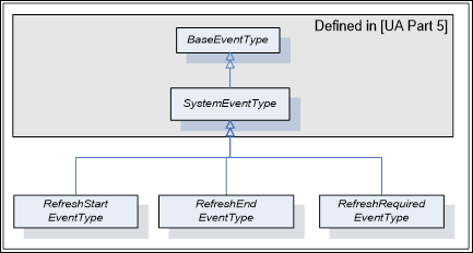
Figure 25 – Refresh Related Event Hierarchy
This EventType is used by a Server to mark the beginning of a Refresh Notification cycle. Its representation in the AddressSpace is formally defined in Table 133.
Table 133 – RefreshStartEventType definition
|
Attribute |
Value |
||||
|
BrowseName |
RefreshStartEventType |
||||
|
IsAbstract |
True |
||||
|
References |
NodeClass |
BrowseName |
DataType |
TypeDefinition |
ModellingRule |
|
|
|
|
|
||
|
Subtype of the SystemEventType defined in 10000-5, i.e. it has HasProperty References to the same Nodes. |
|||||
|
ConformanceUnits |
|||||
|
A & C Refresh |
|||||
|
A & C Refresh2 |
|||||
This EventType is used by a Server to mark the end of a Refresh Notification cycle. Its representation in the AddressSpace is formally defined in Table 134.
Table 134 – RefreshEndEventType definition
|
Attribute |
Value |
||||
|
BrowseName |
RefreshEndEventType |
||||
|
IsAbstract |
True |
||||
|
References |
NodeClass |
BrowseName |
DataType |
TypeDefinition |
ModellingRule |
|
|
|
|
|
||
|
Subtype of the SystemEventType defined in 10000-5, i.e. it has HasProperty References to the same Nodes. |
|||||
|
ConformanceUnits |
|||||
|
A & C Refresh |
|||||
|
A & C Refresh2 |
|||||
This EventType is used by a Server to indicate that a significant change has occurred in the Server or in the subsystem below the Server that may or does invalidate the Condition state of a Subscription. Its representation in the AddressSpace is formally defined in Table 135.
Table 135 – RefreshRequiredEventType definition
|
Attribute |
Value |
||||
|
BrowseName |
RefreshRequiredEventType |
||||
|
IsAbstract |
True |
||||
|
References |
NodeClass |
BrowseName |
DataType |
TypeDefinition |
ModellingRule |
|
|
|
|
|
||
|
Subtype of the SystemEventType defined in 10000-5, i.e. it has HasProperty References to the same Nodes. |
|||||
|
ConformanceUnits |
|||||
|
A & C Refresh |
|||||
|
A & C Refresh2 |
|||||
When a Server detects an Event queue overflow, it shall track if any Condition Events have been lost, if any Condition Events were lost, it shall issue a RefreshRequiredEventType Event to the Client after the Event queue is no longer in an overflow state.
The HasCondition ReferenceType is a concrete ReferenceType and can be used directly. It is a subtype of NonHierarchicalReferences. The representation in the AddressSpace is specified in Table 136.
The semantic of this ReferenceType is to specify the relationship between a ConditionSource and its Conditions. Each ConditionSource shall be the target of a HasEventSource Reference or a sub type of HasEventSource. The AddressSpace organisation that shall be provided for Clients to detect Conditions and ConditionSources is defined in Clause 6. Various examples for the use of this ReferenceType can be found in B.2.
HasCondition References can be used in the Type definition of an Object or a Variable. In this case, the SourceNode of this ReferenceType shall be an ObjectType or VariableType Node or one of their InstanceDeclaration Nodes. The TargetNode shall be a Condition instance declaration or a ConditionType. The following rules for instantiation apply:
· All HasCondition References used in a Type shall exist in instances of these Types as well.
· If the TargetNode in the Type definition is a ConditionType, the same TargetNode will be referenced on the instance.
HasCondition References may be used solely in the instance space when they are not available in Type definitions. In this case the SourceNode of this ReferenceType shall be an Object, Variable or Method Node. The TargetNode shall be a Condition instance or a ConditionType.
Table 136 – HasCondition ReferenceType Definition
|
Attributes |
Value |
||
|
BrowseName |
HasCondition |
||
|
InverseName |
IsConditionOf |
||
|
Symmetric |
False |
||
|
IsAbstract |
False |
||
|
References |
NodeClass |
BrowseName |
Comment |
|
|
|
|
|
|
ConformanceUnits |
|||
|
A & C Basic |
|||
Table 137 defines the StatusCodes defined for Alarm & Conditions.
Table 137 – Alarm & Condition result codes
|
Symbolic Id |
Description |
|
Bad_ConditionAlreadyEnabled |
The addressed Condition is already enabled. |
|
Bad_ConditionAlreadyDisabled |
The addressed Condition is already disabled. |
|
Bad_ConditionAlreadyShelved |
The Alarm is already in a shelved state. |
|
Bad_ConditionBranchAlreadyAcked |
The EventId does not refer to a state that needs acknowledgement. |
|
Bad_ConditionBranchAlreadyConfirmed |
The EventId does not refer to a state that needs confirmation. |
|
Bad_ConditionNotShelved |
The Alarm is not in the requested shelved state. |
|
Bad_DialogNotActive |
The DialogConditionType instance is not in Active state. |
|
Bad_DialogResponseInvalid |
The selected option is not a valid index in the ResponseOptionSet array. |
|
Bad_EventIdUnknown |
The specified EventId is not known to the Server. |
|
Bad_RefreshInProgress |
A ConditionRefresh operation is already in progress. |
|
Bad_ShelvingTimeOutOfRange |
The provided Shelving time is outside the range allowed by the Server for Shelving |
This section describes behaviour that is expected from an OPC UA Server that is implementing the A & C Information Model. In particular this section describes specific behaviours that apply to various aspect of the A & C Information Model.
In some implementation of an OPC UA A & C Server, the Alarms and Condition are provided by an underlying system. The expected behaviour of an A & C Server when it is encountering communication problems with the underlying system is:
· If communication fails to the underlying system,
– For any Event field related information that is exposed in the address space, the Value/StatusCode obtained when reading the Event fields that are associated with the communication failure shall have a value of NULL and a StatusCode of Bad_CommunicationError.
– For Subscriptions that contain Conditions for which the failure applies, the effected Conditions generate an Event, if the Retain field is set to True. These Events shall have their Event fields that are associated with the communication failure contain a StatusCode of Bad_CommunicationError for the value.
– A Condition of the SystemOffNormalAlarmType shall be used to report the communication failure to Alarm Clients. The NormalState field shall contain the NodeId of the Variable that indicates the status of the underlying system.
· For start-up of an A & C Server that is obtaining A & C information from an already running underlying system:
– If a value is unavailable for an Event field that is being reported due to a start-up of the UA Server (i.e. the information is just not available for the Event) the Event field shall contain a StatusCode set to Bad_WaitingForInitialData for the value.
– If the Time field is normally provided by the underlying system and is unavailable, the Time shall be reported as a StatusCode with a value of Bad_WaitingForInitialData.
In an OPC UA Server that is implementing the A & C Information Model and that is configured to be a redundant OPC UA Server the following behaviour is expected:
· The EventId is used to uniquely identify an Event. For an Event that is in each of the redundant Servers, it shall be identical. This applies to all standard Events, Alarms and Conditions. This may be accomplished by sharing of information between redundant Server (such as actual Events) or it may be accomplished by providing a strict EventId generating algorithm that will generate an identical EventId for each Event
· It is expected that for cold or warm failovers of redundant Servers, Subscription for Events shall require a Refresh operation. The Client shall initiate this Refresh operation.
· It is expected that for hot failovers of redundant Servers, Subscriptions for Events may require a Refresh operation. The Server shall issue a RefreshRequiredEventType Event if it is required.
· For transparent redundancy, a Server shall not require any action be performed by a Client.
The AddressSpace organisation described in this Clause allows Clients to detect Conditions and ConditionSources. An additional hierarchy of Object Nodes that are notifiers may be established to define one or more areas; the Client can subscribe to specific areas to limit the Event Notifications sent by the Server. Additional examples can be found in Clause B.2.
HasNotifier and HasEventSource References are used to expose the hierarchical organization of Event notifying Objects and ConditionSources. An Event notifying Object represents typically an area of Operator responsibility. The definition of such an area configuration is outside the scope of this standard. If areas are available, they shall be linked together and with the included ConditionSources using the HasNotifier and the HasEventSource Reference Types. The Server Object shall be the root of this hierarchy.
Figure 26 shows such a hierarchy. Note that HasNotifier is a sub-type of HasEventSource. I.e. the target Node of a HasNotifier Reference (an Event notifying Object) may also be a ConditionSource. The HasEventSource Reference is used if the target Node is a ConditionSource but cannot be used as Event notifier. See 10000-3 for the formal definition of these Reference Types.
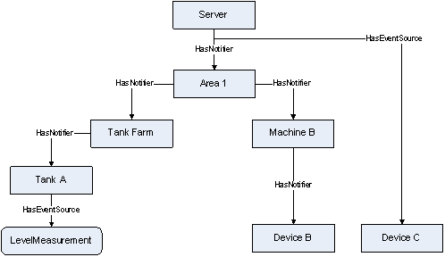
Figure 26 – Typical HasNotifier Hierarchy
HasCondition is used to reference Conditions. The Reference is from a ConditionSource to a Condition instance or – if no instance is exposed by the Server – to the ConditionType.
Clients can locate Conditions by first browsing for ConditionSources following HasEventSource References (including sub-types like the HasNotifier Reference) and then browsing for HasCondition References from all target Nodes of the discovered References.
Figure 27 shows the application of the HasCondition Reference in a HasNotifier hierarchy. The Variable LevelMeasurement and the Object “Device B” Reference Condition instances. The Object “Tank A” References a ConditionType (MySystemAlarmType) indicating that a Condition exists but is not exposed in the AddressSpace.
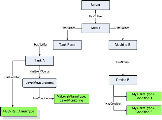
Figure 27 – Use of HasCondition in a HasNotifier hierarchy
Figure 28 shows the use of the HasCondition Reference and the HasEventSource Reference in an InstanceDeclaration. They are used to indicate what References and Conditions are available on the instance of the ObjectType.
The use of the HasEventSource Reference in the context of InstanceDeclarations and TypeDefinition Nodes has no effect for Event generation.
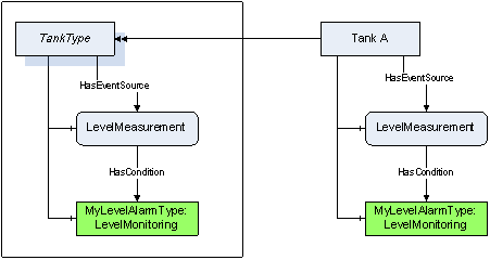
Figure 28 – Use of HasCondition in an InstanceDeclaration
Use of HasCondition in a VariableType is a special use case since Variables (and VariableTypes) may not have Conditions as components. Figure 29 provides an example of this use case. Note that there is no component relationship for the “LevelMonitoring” Alarm. It is Server-specific whether and where they assign a HasComponent Reference.
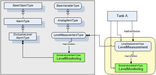
Figure 29 – Use of HasCondition in a VariableType
The state of alarms is affected by the state of the process, equipment, system or plant. For example, when a tank is taken out of service, the level alarms associated with the tank would be no longer used, until the tank is returned to service. This section describes ReferenceTypes that can be used by a StateMachine to indicate that a specific Effect on Alarms caused by the transition of a StateMachine. StateMachines that describe the state of a process, system or equipment can vary, but an example StateMachine is provided in Annex F.
The HasEffectDisable ReferenceType is a concrete ReferenceType and can be used directly. It is a subtype of HasEffect.
The semantic of this ReferenceType is to point form a Transition to an Alarm that will be disabled.
· If the Reference is to an Object then all Alarms in the HasNotifier hierarchy below that Object are disabled,
· If the target is an AlarmType then all instances of that AlarmType in the HasNotifier hierarchy below the Object containing the StateMachine are disabled,
· If the target is an Alarm instance then the given Alarm instance is disabled.
The SourceNode of this ReferenceType shall be an Object of the ObjectType TransitionType or one of its subtypes. The TargetNode can be of an Object or AlarmType.
The representation of the HasEffectDisable ReferenceType in the AddressSpace is specified in Table 138
Table 138 – HasEffectDisable ReferenceType
|
Attributes |
Value |
||
|
BrowseName |
HasEffectDisable |
||
|
InverseName |
MayBeDisabledBy |
||
|
Symmetric |
False |
||
|
IsAbstract |
False |
||
|
References |
NodeClass |
BrowseName |
Comment |
|
|
|
|
|
|
ConformanceUnits |
|||
|
A & C StateMachine Trigger |
|||
The HasEffectEnable ReferenceType is a concrete ReferenceType and can be used directly. It is a subtype of HasEffect.
The semantic of this ReferenceType is to point form a Transition to an Alarm that will be enabled.
· If the Reference is to an Object then all Alarms in the HasNotifier hierarchy below that Object are enabled,
· If the target is an AlarmType then all instances of that AlarmType in the HasNotifier hierarchy below the Object containing the StateMachine are enabled
· If the target is an Alarm instance then the given Alarm instance is enabled.
The SourceNode of this ReferenceType shall be an Object of the ObjectType TransitionType or one of its subtypes. The TargetNode can be of any NodeClass.
The representation of the HasEffectEnable ReferenceType in the AddressSpace is specified in Table 139
Table 139 – HasEffectEnable ReferenceType
|
Attributes |
Value |
||
|
BrowseName |
HasEffectEnable |
||
|
InverseName |
MayBeEnabledBy |
||
|
Symmetric |
False |
||
|
IsAbstract |
False |
||
|
References |
NodeClass |
BrowseName |
Comment |
|
|
|
|
|
|
ConformanceUnits |
|||
|
A & C Statemachine Trigger |
|||
The HasEffectSuppressed ReferenceType is a concrete ReferenceType and can be used directly. It is a subtype of HasEffect.
The semantic of this ReferenceType is to point form a Transition to an Alarm that will be suppressed.
· If the reference is to an Object then all Alarms in the EventNotifier hierarchy below that Object are suppressed,
· If the target is an AlarmType then all instance of that AlarmType in the HasNotifier hierarchy below the Object containing the StateMachine are suppressed,
· If the target is an Alarm instance then the given Alarm instance is suppressed.
The SourceNode of this ReferenceType shall be an Object of the ObjectType TransitionType or one of its subtypes. The TargetNode can be of any NodeClass.
The representation of the HasEffectSuppressed ReferenceType in the AddressSpace is specified in Table 140
Table 140 – HasEffectSuppressed ReferenceType
|
Attributes |
Value |
||
|
BrowseName |
HasEffectSuppressed |
||
|
InverseName |
MayBeSuppressedBy |
||
|
Symmetric |
False |
||
|
IsAbstract |
False |
||
|
References |
NodeClass |
BrowseName |
Comment |
|
|
|
|
|
|
ConformanceUnits |
|||
|
A & C Statemachine Suppression Trigger |
|||
The HasEffectUnsuppressed ReferenceType is a concrete ReferenceType and can be used directly. It is a subtype of HasEffect.
The semantic of this ReferenceType is to point form a Transition to an Alarm that will no longer be suppressed.
· If the Reference is to an Object then all Alarms in the HasNotifier hierarchy below that Object are removed from being suppressed,
· If the target is an AlarmType then all instance of that AlarmType are no longer suppressed below the Object containing the StateMachine,
· if the target is an Alarm instance then the given Alarm instance is no longer suppressed. No errors are logged if the Alarm was not suppressed.
The SourceNode of this ReferenceType shall be an Object of the ObjectType TransitionType or one of its subtypes. The TargetNode can be of any NodeClass.
The representation of the HasEffectUnsuppressed ReferenceType in the AddressSpace is specified in Table 141.
Table 141 – HasEffectUnsuppressed ReferenceType
|
Attributes |
Value |
||
|
BrowseName |
HasEffectUnsuppressed |
||
|
InverseName |
MayBeUnsuppressedBy |
||
|
Symmetric |
False |
||
|
IsAbstract |
False |
||
|
References |
NodeClass |
BrowseName |
Comment |
|
|
|
|
|
|
ConformanceUnits |
|||
|
A & C Statemachine Suppression Trigger |
|||
In a system an Object might have multiple Alarms associated with it. These Alarms might be directly Referenced by an Object or they might have no direct References from the Object to the Alarm. Alarms might also be related to Objects that are nested under the Object. When the Object is represented in a graphic in a plant, it is often important to be able to see if there is an active Alarm associated with it. This indication could just be a flashing value or flashing image or a change in color of the image.
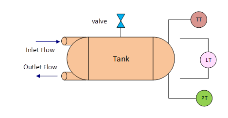
Figure 30 - AlarmSummary equipment example
For example if there is a tank (illustrated in Figure 30). The tank might have a level meter, a temperature gauge and a pressure gauge. It might also have a flow meter on both an inlet and an outlet. The tank might also have a pressure release valve. The information model that might result from this equipment is illustrated in Figure 31
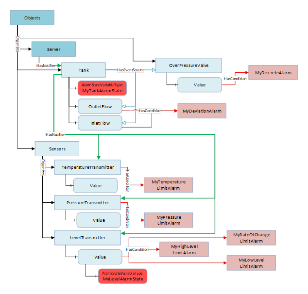
Figure 31 - AlarmSummary Equipment Object Example
All of these sub-objects might have unique alarms associated with them, such as limit alarms on the temperature and levels, maybe rate of change alarm as well as limit alarms on the pressure. Maybe some advanced Alarms that are associated with the tank for an invalid state (in the inlet flow > 0 and the outlet flow is > 0). Maybe a discrete alarm on the pressure release valve, i.e. when it is open it is an alarm. The overall alarm state of the Tank might need to be displayed on a graphic or maybe the LevelTransmitter’s value needs to indicate that there is an alarm associated with the value.
An instance of AlarmStateVariableType can be assigned to any Object or Variable. The instance will provide a summary of the Alarms associated with the parent Variable or Object (the Source of the HasComponent Reference for this instance)
Table 142 – AlarmStateVariableType definition
|
Attribute |
Value |
||||
|
BrowseName |
AlarmStateVariableType |
||||
|
DataType |
AlarmMask |
||||
|
ValueRank |
-1 (-1 = Scalar) |
||||
|
IsAbstract |
False |
||||
|
References |
NodeClass |
BrowseName |
DataType |
TypeDefinition |
Modelling |
|
Subtype of the BaseDataVariableType defined in 10000-5. |
|||||
|
HasProperty |
Variable |
HighestActiveSeverity |
UInt16 |
PropertyType |
Mandatory |
|
HasProperty |
Variable |
HighestUnackSeverity |
UInt16 |
PropertyType |
Mandatory |
|
HasProperty |
Variable |
ActiveCount |
UInt32 |
PropertyType |
Mandatory |
|
HasProperty |
Variable |
UnacknowledgedCount |
UInt32 |
PropertyType |
Mandatory |
|
HasProperty |
Variable |
UnconfirmedCount |
UInt32 |
PropertyType |
Mandatory |
|
HasProperty |
Variable |
Filter |
ContentFilter |
PropertyType |
Mandatory |
|
ConformanceUnits |
|||||
|
A & C Summary |
|||||
HighestActiveSeverity – the highest Severity of any active Alarm.
HighestUnackSeverity – the highest Severity of any Unacknowledged Alarm
ActiveCount – a count of the number of active Alarms
UnacknowledgedCount – a count of the number of Unacknowledged Alarms
UnconfirmedCount – a count of the number of Unconfirmed Alarms. If alarm confirmation is not supported this count shall be zero.
Filter – provides a ContentFilter that can be used to restrict what alarms are processed as part of the AlarmStateVariableType. If no filter is required the ContentFilter can be null.
This OptionSet defines flags indicating the summary of alarm states.
The AlarmMask values are formally defined in Table 143.
Table 143 – AlarmMask values
|
Value |
Bit No. |
Description |
|
Active |
0 |
This bit is set if there are active Alarms |
|
Unacknowledged |
1 |
This bit is set if there are Unacknowledged Alarms |
|
Unconfirmed |
2 |
This bit is set if there are Unconfirmed Alarms |
The AlarmMask representation in the AddressSpace is formally defined in Table 144.
Table 144 – AlarmMask definition
|
Attribute |
Value |
|||||
|
BrowseName |
AlarmMask |
|||||
|
IsAbstract |
False |
|||||
|
References |
NodeClass |
BrowseName |
DataType |
TypeDefinition |
Other |
|
|
Subtype of the UInt16 type defined in 10000-5 |
||||||
|
0:HasProperty |
Variable |
0:OptionSetValues |
0:LocalizedText[] |
0:PropertyType |
|
|
|
ConformanceUnits |
||||||
|
A & C Summary |
||||||
The goal of a well-designed alarm system is to ensure that an Operator is made aware of issues, both critical and non-critical, but is not overwhelmed by alarms/alerts or other messages. When designing an alarm system, criteria are defined for alarm rates and general performance of the system at various levels (Operator station, plant area, overall system etc.). Evaluating the performance of an alarm system with regard to these design criteria requires the collection of alarm metrics. These metrics provide summaries of alarm rates and other alarm related information.
This section defines a standard structure for metrics. This structure can be implemented at multiple levels allowing a Server to collect metrics as needed. For example, an Object of this type might be added to the Server Object providing a summary of the Alarm performance for the entire Server. An instance might also be provided on an Object that includes a HasNotifier hierarchy, such as a tank Object. In this case, it would provide the summary of all of the Alarms that are part of the tank HasNotifier hierarchy.
This ObjectType is used for metric information. The ObjectType is formally defined in Table 145.
Table 145 – AlarmMetricsType Definition
|
Attribute |
Value |
|||||
|
BrowseName |
AlarmMetricsType |
|||||
|
IsAbstract |
False |
|||||
|
References |
NodeClass |
BrowseName |
DataType |
TypeDefinition |
Modelling |
|
|
Subtype of the BaseObjectType defined in 10000-5. |
||||||
|
HasComponent |
Variable |
AlarmCount |
UInt32 |
BaseDataVariableType |
Mandatory |
|
|
HasComponent |
Variable |
StartTime |
UtcTime |
BaseDataVariableType |
Mandatory |
|
|
HasComponent |
Variable |
MaximumActiveState |
Duration |
BaseDataVariableType |
Mandatory |
|
|
HasComponent |
Variable |
MaximumUnAck |
Duration |
BaseDataVariableType |
Mandatory |
|
|
HasComponent |
Variable |
CurrentAlarmRate |
Double |
AlarmRateVariableType |
Mandatory |
|
|
HasComponent |
Variable |
MaximumAlarmRate |
Double |
AlarmRateVariableType |
Mandatory |
|
|
HasComponent |
Variable |
MaximumReAlarmCount |
UInt32 |
BaseDataVariableType |
Mandatory |
|
|
HasComponent |
Variable |
AverageAlarmRate |
Double |
AlarmRateVariableType |
Mandatory |
|
|
HasComponent |
Method |
Reset |
|
|
Mandatory |
|
|
A & C Alarm Metrics |
||||||
An instance of AlarmMetricsType can be added, with a HasComponent reference, to any Object that has its “SubscribeToEvents” bit set within the EventNotifier Attribute. It will collect the Alarm metrics for all Alarm sources assigned to this notifier Object. For example, if Alarm metrics are desired for Tank A Object (see Figure B.5) that is in the HasNotifier hierarchy than an instance of this object would be referenced by the Tank A object. When this object is associated with the Server Object it will report Alarm metrics for the entire Server.
AlarmCount is the total count of Alarms since the last restart of the system or reset of this counter.
StartTime is the time at which the Server started or the time of the last Reset Method invocation, whichever is later.
MaximumActiveState is the maximum time for which an Alarm was in the active state.
MaximumUnAck is the maximum time for which an Alarm was in the unacknowledged state.
CurrentAlarmRate is the sum of Alarms that occurred in the last Rate number of minutes (see 9.3). This sum should not include nuisance Alarms (i.e. chattering alarms). It is updated every Rate number of minutes.
MaximumAlarmRate is the maximum Alarm rate detected since the start of the Server, where the rate is calculated as for CurrentAlarmRate.
MaximumReAlarmCount is the maximum ReAlarmCount for any Alarm.
AverageAlarmRate is the average Alarm rate since the start of the Server or the last invocation of Reset Method, where the rate is calculated as for CurrentAlarmRate.
Reset is a Method that will reset all of the counters, rates or times in this Object
This variable type provides a unit field for the rate for which the Alarm diagnostic applies.
Table 146 – AlarmRateVariableType Definition
|
Attribute |
Value |
|||||
|
BrowseName |
AlarmRateVariableType |
|||||
|
IsAbstract |
False |
|||||
|
ValueRank |
Scalar |
|||||
|
DataType |
Double |
|||||
|
References |
NodeClass |
BrowseName |
DataType |
TypeDefinition |
ModellingRule |
|
|
HasProperty |
Variable |
Rate |
UInt16 |
PropertyType |
Mandatory |
|
|
ConformanceUnits |
||||||
|
A & C Alarm Metrics |
||||||
Rate – is the number of minutes over which the item is calculated.
The Reset Method is used reset all of the counters, rates and time in the Object
Signature
Reset();
Method Result Codes in Table 53 (defined in Call Service)
Table 147 – Suppress result codes
|
Result Code |
Description |
|
Bad_MethodInvalid |
The MethodId provided does not correspond to the ObjectId provided. See 10000-4 for the general description of this result code. |
|
Bad_NodeIdInvalid |
Used to indicate that the specified ObjectId is not valid. See 10000-4 for the general description of this result code. |
Comments
The Reset Method will clear all setting in the diagnostic object and initialize them to zero.
Table 148 specifies the AddressSpace representation for the Reset Method.
Table 148 – Reset Method AddressSpace Definition
|
Attribute |
Value |
||||
|
BrowseName |
Reset |
||||
|
References |
NodeClass |
BrowseName |
DataType |
TypeDefinition |
ModellingRule |
|
|
|
|
|
|
|
|
AlwaysGeneratesEvent |
ObjectType |
AuditUpdateMethodEventType |
Defined in 10000-5 |
||
|
ConformanceUnits |
|||||
|
A & C Alarm Metrics |
|||||
If Auditing is supported, this Method shall generate an Event of AuditConditionMethodEventType for all invocations of the Method.
Annex A (informative)
Recommended localized names
A.1 Recommended state names for TwoState Variables
The recommended state display values for the LocaleId “en” are listed in Table A.1 and the recommended DisplayNames are listed in Table A.2
Table A.1 – Recommended state names for LocaleId “en”
|
ConditionType |
State Variable |
False State Name |
True State Name |
|
ConditionType |
EnabledState |
Disabled |
Enabled |
|
DialogConditionType |
DialogState |
Inactive |
Active |
|
AcknowledgeableConditionType
|
AckedState |
Unacknowledged |
Acknowledged |
|
ConfirmedState |
Unconfirmed |
Confirmed |
|
|
AlarmConditionType |
ActiveState |
Inactive |
Active |
|
SuppressedState |
Unsuppressed |
Suppressed |
|
|
OutOfServiceState |
In Service |
Out of Service |
|
|
SilenceState |
Not Silenced |
Silenced |
|
|
LatchedState |
Unlatched |
Latched |
|
|
NonExclusiveLimitAlarmType |
HighHighState |
HighHigh inactive |
HighHigh active |
|
HighState |
High inactive |
High active |
|
|
LowState |
Low inactive |
Low active |
|
|
LowLowState |
LowLow inactive |
LowLow active |
Table A.2 – Recommended DisplayNames for LocaleId “en”
|
ConditionType |
BrowseName |
DisplayName |
|
Shelved |
Unshelved |
Unshelved |
|
TimedShelved |
TimedShelved |
|
|
OneShotShelved |
OneShotShelved |
|
|
Exclusive |
HighHigh |
HighHigh |
|
High |
High |
|
|
Low |
Low |
|
|
LowLow |
LowLow |
The recommended state display values for the LocaleId “de” are listed in Table A.3 and the recommended DisplayNames are listed in Table A.4.
Table A.3 – Recommended state names for LocaleId “de”
|
ConditionType |
State Variable |
False State Name |
True State Name |
|
ConditionType |
EnabledState |
Ausgeschaltet |
Eingeschaltet |
|
DialogConditionType |
DialogState |
Inaktiv |
Aktiv |
|
AcknowledgeableConditionType
|
AckedState |
Unquittiert |
Quittiert |
|
ConfirmedState |
Unbestätigt |
Bestätigt |
|
|
AlarmConditionType |
ActiveState |
Inaktiv |
Aktiv |
|
SuppressedState |
Nicht unterdrückt |
Unterdrückt |
|
|
OutOfServiceState |
InBetrieb |
AußerBetrieb |
|
|
SilenceState |
Nicht Stumm |
Stumm |
|
|
LatchedState |
Entriegelt |
Verriegelt |
|
|
NonExclusiveLimitAlarmType |
HighHighState |
HighHigh inaktiv |
HighHigh aktiv |
|
HighState |
High inaktiv |
High aktiv |
|
|
LowState |
Low inaktiv |
Low aktiv |
|
|
LowLowState |
LowLow inaktiv |
LowLow aktiv |
Table A.4 – Recommended DisplayNames for LocaleId “de”
|
ConditionType |
BrowseName |
DisplayName |
|
Shelved |
Unshelved |
NichtZurückgestellt |
|
TimedShelved |
BefristetZurückgestellt |
|
|
OneShotShelved |
EinmaligZurückgestellt |
|
|
Exclusive |
HighHigh |
HighHigh |
|
High |
High |
|
|
Low |
Low |
|
|
LowLow |
LowLow |
The recommended state display values for the LocaleId “fr” are listed in Table A.5 and the recommended DisaplayNames are listed inTable A.6.
Table A.5 – Recommended state names for LocaleId “fr”
|
ConditionType |
State Variable |
False State Name |
True State Name |
|
ConditionType |
EnabledState |
Hors Service |
En Service |
|
DialogConditionType |
DialogState |
Inactive |
Active |
|
AcknowledgeableConditionType
|
AckedState |
Non-acquitté |
Acquitté |
|
ConfirmedState |
Non-Confirmé |
Confirmé |
|
|
AlarmConditionType |
ActiveState |
Inactive |
Active |
|
SuppressedState |
Présent |
Supprimé |
|
|
OutOfServiceState |
En Fonction |
Hors Fonction |
|
|
SilenceState |
Non-Muette |
Muette |
|
|
LatchedState |
Déverrouillé |
Verrouillé |
|
|
NonExclusiveLimitAlarmType |
HighHighState |
Très Haute inactive |
Très Haute active |
|
HighState |
Haute inactive |
Haute active |
|
|
LowState |
Basse inactive |
Basse active |
|
|
LowLowState |
Très basse inactive |
Très basse active |
Table A.6 – Recommended DisplayNames for LocaleId “fr”
|
ConditionType |
BrowseName |
DisplayName |
|
Shelved |
Unshelved |
Surveillée |
|
TimedShelved |
MiseDeCotéTemporelle |
|
|
OneShotShelved |
MiseDeCotéUnique |
|
|
Exclusive |
HighHigh |
TrèsHaute |
|
High |
Haute |
|
|
Low |
Basse |
|
|
LowLow |
TrèsBasse |
A.2 Recommended dialog response options
The recommended Dialog response option names in different locales are listed in Table A.7.
Table A.7 – Recommended dialog response options
|
Locale “en” |
Locale “de” |
Locale “fr” |
|
Ok |
OK |
Ok |
|
Cancel |
Abbrechen |
Annuler |
|
Yes |
Ja |
Oui |
|
No |
Nein |
Non |
|
Abort |
Abbrechen |
Abandonner |
|
Retry |
Wiederholen |
Réessayer |
|
Ignore |
Ignorieren |
Ignorer |
|
Next |
Nächster |
Prochain |
|
Previous |
Vorheriger |
Precedent |
Annex B (informative)
Examples
B.1 Examples for Event sequences from Condition instances
The following examples show the Event flow for typical Alarm situations. The tables list the value of state Variables for each Event Notification.
B.1.2 Server maintains current state only
This example is for Servers that do not support previous states and therefore do not create and maintain Branches of a single Condition.
Figure B.1 shows an Alarm as it becomes active and then inactive and also the acknowledgement and confirmation cycles. Table B.1 lists the values of the state Variables. All Events are coming from the same Condition instance and therefore have the same ConditionId.
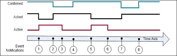
Figure B.1 – Single state example
Table B.1 – Example of a Condition that only keeps the latest state
|
EventId |
BranchId |
Active |
Acked |
Confirmed |
Retain |
Description |
|
-*) |
NULL |
False |
True |
True |
False |
Initial state of Condition. |
|
1 |
NULL |
True |
False |
True |
True |
Alarm goes active. |
|
2 |
NULL |
True |
True |
False |
True |
Condition acknowledged Confirm required |
|
3 |
NULL |
False |
True |
False |
True |
Alarm goes inactive. |
|
4 |
NULL |
False |
True |
True |
False |
Condition confirmed |
|
5 |
NULL |
True |
False |
True |
True |
Alarm goes active. |
|
6 |
NULL |
False |
False |
True |
True |
Alarm goes inactive. |
|
7 |
NULL |
False |
True |
False |
True |
Condition acknowledged, Confirm required. |
|
8 |
NULL |
False |
True |
True |
False |
Condition confirmed. |
|
*) The first row is included to illustrate the initial state of the Condition. This state will not be reported by an Event. |
||||||
B.1.3 Server maintains previous states
This example is for Servers that are able to maintain previous states of a Condition and therefore create and maintain Branches of a single Condition.
Figure B.2 illustrates the use of branches by a Server requiring acknowledgement of all transitions into Active state, not just the most recent transition. In this example no acknowledgement is required on a transition into an inactive state. Table B.2 lists the values of the state Variables. All Events are coming from the same Condition instance and have therefore the same ConditionId.
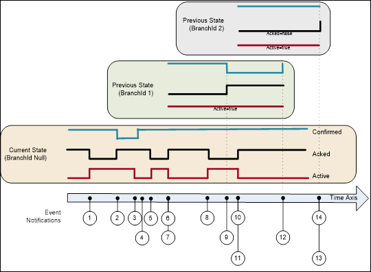
Figure B.2 – Previous state example
Table B.2 – Example of a Condition that maintains previous states via branches
|
EventId |
BranchId |
Active |
Acked |
Confirmed |
Retain |
Description |
|
a) |
NULL |
False |
True |
True |
False |
Initial state of Condition. |
|
1 |
NULL |
True |
False |
True |
True |
Alarm goes active. |
|
2 |
NULL |
True |
True |
True |
True |
Condition acknowledged requires Confirm |
|
3 |
NULL |
False |
True |
False |
True |
Alarm goes inactive. |
|
4 |
NULL |
False |
True |
True |
False |
Confirmed |
|
5 |
NULL |
True |
False |
True |
True |
Alarm goes active. |
|
6 |
NULL |
False |
True |
True |
True |
Alarm goes inactive. |
|
7 |
1 |
True |
False |
True |
True b) |
Prior state needs acknowledgment. Branch #1 created. |
|
8 |
NULL |
True |
False |
True |
True |
Alarm goes active again. |
|
9 |
1 |
True |
True |
False |
True |
Prior state acknowledged, Confirm required. |
|
10 |
NULL |
False |
True |
True |
True b) |
Alarm goes inactive again. |
|
11 |
2 |
True |
False |
True |
True |
Prior state needs acknowledgment. Branch #2 created. |
|
12 |
1 |
True |
True |
True |
False |
Prior state confirmed. Branch #1 deleted. |
|
13 |
2 |
True |
True |
True |
False |
Prior state acknowledged, Auto Confirmed by system Branch #2 deleted. c) |
|
14 |
NULL |
False |
True |
True |
False |
No longer of interest. |
|
a) The first row is included to illustrate the initial state of the Condition. This state will not be reported by an Event. Notes on specific situations shown with this example: If the current state of the Condition is acknowledged then the Acked flag is set and the new state is reported (Event #2). If the Condition state changes before it can be acknowledged (Event #6) then a branch state is reported (Event #7). Timestamps for the Events #6 and #7 is identical. The branch state can be updated several times (Events #9) before it is cleared (Event #12). A single Condition can have many branch states active (Events #11) b) It is recommended as in this table to leave Retain=True as long as there exist previous states (branches). c) The system Auto confirms this event, since a confirmation is that the operator has taken some action. The confirmation of the previous state (line 12) indicates that the operator has taken an action and this transition does not require a separate confirmation. |
||||||
B.1.4 Server current-State Model with Suppression
This example adds additional fields to the model illustrated in B.1.2. This example does not use acknowledge or confirm – it assumes that the alarm is automatically acknowledged (and does not support confirm). It does add OutOfServiceState and SuppressedState.
Figure B.3 shows an Alarm as it becomes active, is suppressed or is placed out of service and then inactive. Table B.3 lists the values of the state Variables. All Events are coming from the same Condition instance and therefore have the same ConditionId. The Client subscription includes an event filter that excludes suppressed or out of service conditions (i.e. SuppressedState = True or OutOfServiceState = True). The events shown in green are delivered to the Client. The Retain column indicates the global value of the Retain flag. The “Retain sent” column indicates the overridden value sent in a notification if SupportsFilteredRetain is True. If SupportsFilteredRetain is False the value from the Retain column is sent.
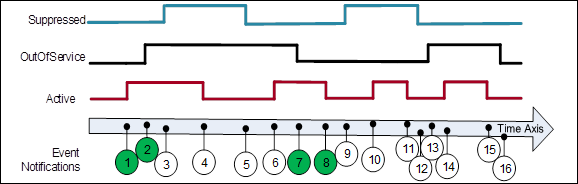
Figure B.3 – SuppressedState and OutOfServiceState example
Table B.3 – Example of a Condition that is Suppressed / OutOfService
|
EventId |
Active |
Suppressed State |
OutOf Service State |
Retain |
Retain sent |
Event Deliver with Filter |
Description |
|
-*) |
False |
False |
False |
False |
False |
- |
Initial state of Condition. |
|
1 |
True |
False |
False |
True |
True |
Yes |
Alarm goes active. |
|
2 |
True |
False |
True |
True |
False |
Yes |
Placed OutOfService |
|
3 |
True |
True |
True |
True |
False |
No |
Alarm Suppressed; No event since OutOfService |
|
4 |
False |
True |
True |
False |
False |
No |
Alarm goes inactive; No event since OutOfService |
|
5 |
False |
False |
True |
False |
False |
No |
Alarm not Suppressed; No event since not active |
|
6 |
True |
False |
True |
True |
False |
No |
Alarm goes active; No event since OutOfService |
|
7 |
True |
False |
False |
True |
True |
Yes |
Alarm no longer OutOfService; Event generated |
|
8 |
False |
False |
False |
False |
False |
Yes |
Alarm goes inactive |
|
9 |
False |
True |
False |
False |
False |
No |
Alarm Suppressed; No event since not active |
|
10 |
True |
True |
False |
True |
False |
No |
Alarm goes active; No event since Suppressed |
|
11 |
False |
True |
False |
False |
False |
No |
Alarm goes inactive; No event since Suppressed |
|
12 |
False |
False |
False |
False |
False |
No |
Alarm no longer Suppressed |
|
13 |
False |
False |
True |
False |
False |
No |
Placed OutOfService |
|
14 |
True |
False |
True |
True |
False |
No |
Alarm goes active; No event since OutOfService |
|
15 |
False |
False |
True |
False |
False |
No |
Alarm goes inactive; No event since OutOfService |
|
16 |
False |
False |
False |
False |
False |
No |
Alarm no longer OutOfService |
This behaviour occurs when the implementation supports SupportsFilteredRetain flag subscription.
B.1.5 Example for On-Delay, Off Delay and ReAlarmTime
This example illustrates how on-delay, off-delay and alarm dead bands can be used to reduce the number of alarms that are generated / reported (see 5.8). It also illustrates how ReAlarmTime is used to bring an alarm back up to an active state (see Figure B.4).
Some process values may have sudden jumps that are very brief and do not constitute an alarm. For example, a motor on start draws a large current, but quickly come back down. This is a normal motor current load, and should not be alarmed, but a sustained current load is a problem and should be alarmed, by configuring a OnDelay time, the momentary spike will not generate an alarm, since the value has to be above the alarm threshold for the duration of OnDelay.
An AlarmDeadband is used to keep a noise signal from generating multiple Alarm activations a signal once it crosses an alarm limit will not return to norm unless it drops below the limit by the amount of the deadband specified. In the example the process value is jumping up and down around the limit, but the alarm just remains in the same active or acknowledged state. The Alarm can have a deadband for each limit (High vs HighHigh) and these deadbands can be different.
The OffDelay can also be used, much as the OnDelay, except it will keep a Value in alarm even if it drops below a limit, but only very briefly. Again, this setting is used to limit the number of alarms that occur in a system.
The ReAlarmTime is used to ensure that actions are taken to correct the issue that generated an alarm. Some alarms are configured to generate a new alarm if they have been in an active state for the ReAlarmTime period. The Alarm, goes back to an Unacknowledged state, as if it had just occurred.
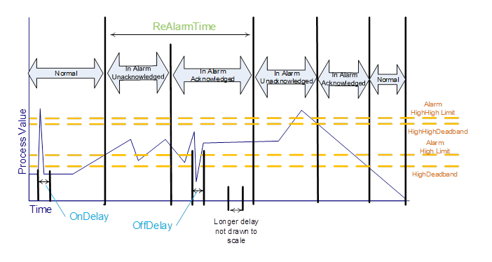
Figure B.4 - Alarm example - On Delay, Off Delay, ReAlarmTime
This Clause provides additional examples for the use of HasNotifier, HasEventSource and HasCondition References to expose the organization of areas and sources with their associated Conditions. This hierarchy is additional to a hierarchy provided with Organizes and Aggregates References.
Figure B.5 illustrates the use of the HasCondition Reference with Condition instances.
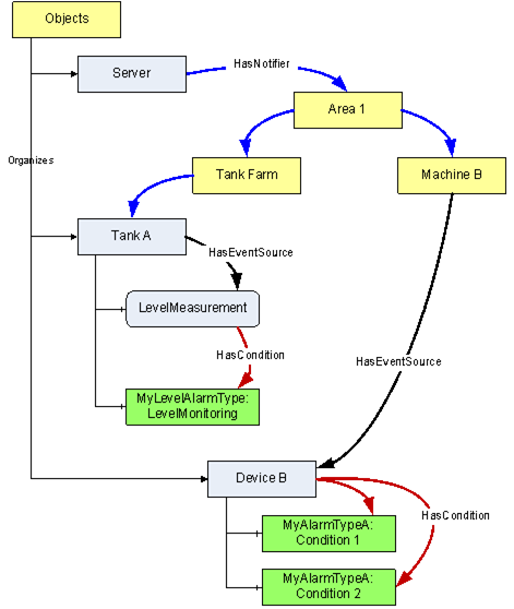
Figure B.5 – HasCondition used with Condition instances
In systems where Conditions are not available as instances, the ConditionSource can reference the ConditionTypes instead. This is illustrated with the example in Figure B.6.
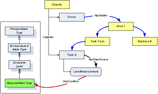
Figure B.6 – HasCondition reference to a Condition type
Figure B.7 provides an example where the HasCondition Reference is already defined in the Type system. The Reference can point to a Condition Type or to an instance. Both variants are shown in this example. A Reference to a Condition Type in the Type system will result in a Reference to the same Type Node in the instance.
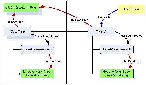
Figure B.7 – HasCondition used with an instance declaration
Annex C
(informative)
Mapping to EEMUA
Table C.1 lists EEMUA terms and how OPC UA terms map to them.
Table C.1 – EEMUA Terms
|
EEMUA Term |
OPC UA Term |
EEMUA Definition |
|
Accepted |
Acknowledged = True |
An Alarm is accepted when the Operator has indicated awareness of its presence. In OPC UA this can be accomplished with the Acknowledge Method. |
|
Active Alarm |
Active = True |
An Alarm Condition which is on (i.e. limit has been exceeded and Condition continues to exist). |
|
Alarm Message |
Message Property (defined in 10000-5.) |
Test information presented to the Operator that describes the Alarm Condition. |
|
Alarm Priority |
Severity Property (defined in 10000-5.) |
The ranking of Alarms by severity and response time. |
|
Alert |
- |
A lower priority Notification than an Alarm that has no serious consequence if ignored or missed. In some Industries also referred to as a Prompt or Warning”. No direct mapping! In UA the concept of Alerts can be accomplished by the use of severity. E.g., Alarms that have a severity below 50 may be considered as Alerts. |
|
Cleared |
Active = False |
An Alarm state that indicates the Condition has returned to normal. |
|
Disable |
Enabled = False |
An Alarm is disabled when the system is configured such that the Alarm will not be generated even though the base Alarm Condition is present. |
|
Prompt |
Dialog |
A request from the control system that the Operator perform some process action that the system cannot perform or that requires Operator authority to perform. |
|
Raised |
Active = True |
An Alarm is Raised or initiated when the Condition creating the Alarm has occurred. |
|
Release |
OneShotShelving |
A ‘release’ is a facility that can be applied to a standing (UA = active) Alarm in a similar way to which Shelving is applied. A released Alarm is temporarily removed from the Alarm list and put on the shelf. There is no indication to the Operator when the Alarm clears, but it is taken off the shelf. Hence, when the Alarm is raised again it appears on the Alarm list in the normal way. |
|
Reset |
Retain = False |
An Alarm is Reset when it is in a state that can be removed from the Display list. OPC UA includes Retain flag which as part of its definition states: “when a Client receives an Event with the Retain flag set to False, the Client should consider this as a Condition/Branch that is no longer of interest, in the case of a “current Alarm display” the Condition/Branch would be removed from the display” |
|
Shelving |
Shelving |
Shelving is a facility where the Operator is able to temporarily prevent an Alarm from being displayed to the Operator when it is causing the Operator a nuisance. A Shelved Alarm will be removed from the list and will not re-annunciate until un-shelved. |
|
Standing |
Active = True |
An Alarm is Standing whilst the Condition persists (Raised and Standing are often used interchangeably). |
|
Suppress |
Suppress |
An Alarm is suppressed when logical criteria are applied to determine that the Alarm should not occur, even though the base Alarm Condition (e.g. Alarm setting exceeded) is present. |
|
Unaccepted |
Acknowledged = False |
An Alarm is accepted when the Operator has indicated awareness of its presence. It is unaccepted until this has been done. |
|
|
|
|
Annex D(informative)
Mapping from OPC A&E to OPC UA A & C
D.1 Overview
Serving as a bridge between COM and OPC UA components, the Alarms and Events proxy and wrapper enable existing A&E COM Clients and Servers to connect to UA Alarms and Conditions components.
Simply stated, there are two aspects to the migration strategy. The first aspect enables a UA Alarms and Conditions Client to connect to an existing Alarms and Events COM Server via a UA Server wrapper. This wrapper is notated from this point forward as the A&E COM UA Wrapper. The second aspect enables an existing Alarms and Events COM Client to connect to a UA Alarms and Conditions Server via a COM proxy. This proxy is notated from this point forward as the A&E COM UA Proxy.
An Alarms and Events COM Client is notated from this point forward as A&E COM Client.
A UA Alarms and Conditions Server is notated from this point forward as UA A & C Server.
The mappings describe generic A&E COM interoperability components. It is recommended that vendors use this mapping if they develop their own components, however, some applications may benefit from vendor specific mappings.
D.2 Alarms and Events COM UA wrapper
Event Areas in the A&E COM Server are represented in the A&E COM UA Wrapper as Objects with a TypeDefinition of BaseObjectType. The EventNotifier Attribute for these Objects always has the SubscribeToEvents flag set to True.
The root Area is represented by an Object with a BrowseName that depends on the UA Server. It is always the target of a HasNotifier Reference from the Server Node. The root Area allows multiple A&E COM Servers to be wrapped within a single UA Server.
The Area hierarchy is discovered with the BrowseOPCAreas and the GetQualifiedAreaName Methods. The Area name returned by BrowseOPCAreas is used as the BrowseName and DisplayName for each Area Node. The QualifiedAreaName is used to construct the NodeId. The NamespaceURI qualifying the NodeId and BrowseName is a unique URI assigned to the combination of machine and COM Server.
Each Area is the target of HasNotifier Reference from its parent Area. It may be the source of one or more HasNotifier References to its child Areas. It may also be a source of a HasEventSource Reference to any sources in the Area.
The A&E COM Server may not support filtering by Areas. If this is the case then no Area Nodes are shown in the UA Server address space. Some implementations could use the AREAS Attribute to provide filtering by Areas within the A&E COM UA Wrapper.
Event Sources in the A&E COM Server are represented in the A&E COM UA Wrapper as Objects with a TypeDefinition of BaseObjectType. If the A&E COM Server supports source filtering then the SubscribeToEvents flag is True and the Source is a target of a HasNotifier Reference. If source filtering is not supported the SubscribeToEvents flag is False and the Source is a target of a HasEventSource Reference.
The Sources are discovered by calling BrowseOPCAreas and the GetQualifiedSourceName Methods. The Source name returned by BrowseOPCAreas is used as the BrowseName and DisplayName. The QualifiedSourceName is used to construct the NodeId. Event Source Nodes are always targets of a HasEventSource Reference from an Area.
Event Categories in the A&E COM Server are represented in the UA Server as ObjectTypes which are subtypes of BaseEventType. The BrowseName and DisplayName of the ObjectType Node for Simple and Tracking Event Types are constructed by appending the text ‘EventType’ to the Description of the Event Category. For Condition Event Types the text ‘AlarmType’ is appended to the Condition Name.
These ObjectType Nodes have a super type which depends on the A&E Event Type, the Event Category Description and the Condition Name; however, the best mapping requires knowledge of the semantics associated with the Event Categories and Condition Names. If an A&E COM UA Wrapper does not know these semantics then Simple Event Types are subtypes of BaseEventType, Tracking Event Types are subtypes of AuditEventType and Condition Event Types are subtypes of the AlarmType. Table D.1 defines mappings for a set of “well known” Category description and Condition Names to a standard super type.
Table D.1 – Mapping from standard Event categories to OPC UA Event types
|
COM A&E Event Type |
Category Description |
Condition Name |
OPC UA EventType |
|
Simple |
--- |
--- |
BaseEventType |
|
Simple |
Device Failure |
--- |
DeviceFailureEventType |
|
Simple |
System Message |
--- |
SystemEventType |
|
Tracking |
--- |
--- |
AuditEventType |
|
Condition |
--- |
--- |
AlarmType |
|
Condition |
Level |
--- |
LimitAlarmType |
|
Condition |
Level |
PVLEVEL |
ExclusiveLevelAlarmType |
|
Condition |
Level |
SPLEVEL |
ExclusiveLevelAlarmType |
|
Condition |
Level |
HI HI |
NonExclusiveLevelAlarmType |
|
Condition |
Level |
HI |
NonExclusiveLevelAlarmType |
|
Condition |
Level |
LO |
NonExclusiveLevelAlarmType |
|
Condition |
Level |
LO LO |
NonExclusiveLevelAlarmType |
|
Condition |
Deviation |
--- |
NonExclusiveDeviationAlarmType |
|
Condition |
Discrete |
--- |
DiscreteAlarmType |
|
Condition |
Discrete |
CFN |
OffNormalAlarmType |
|
Condition |
Discrete |
TRIP |
TripAlarmType |
There is no generic mapping defined for A&E COM sub-Conditions. If an Event Category is mapped to a LimitAlarmType then the sub Condition name in the Event are be used to set the state of a suitable State Variable. For example, if the sub-Condition name is “HI HI” then that means the HighHigh state for the LimitAlarmType is active
For Condition Event Types the Event Category is also used to define subtypes of BaseConditionClassType.
Figure D.1 illustrates how ObjectType Nodes created from the Event Categories and Condition Names are placed in the standard OPC UA HasNotifier hierarchy.
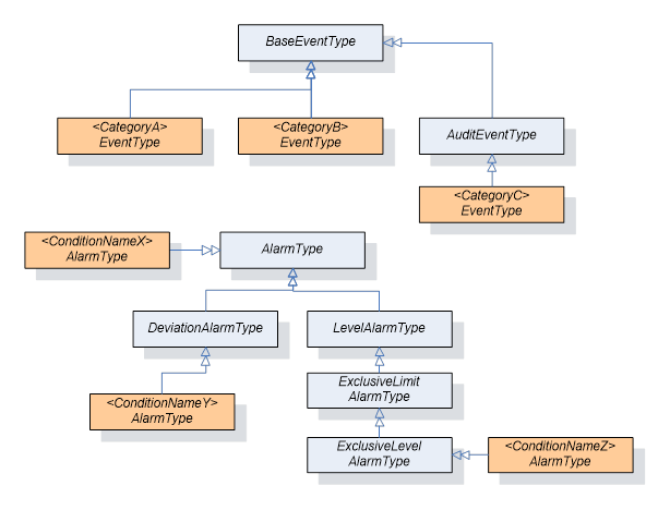
Figure D.1 – The type model of a wrapped COM AE server
Event Attributes in the A&E COM Server are represented in the UA Server as Variables which are targets of HasProperty References from the ObjectTypes which represent the Event Categories. The BrowseName and DisplayName are the description for the Event Attribute. The data type of the Event Attribute is used to set DataType and ValueRank. The NodeId is constructed from the EventCategoryId, ConditionName and the AttributeId.
The A&E COM UA Wrapper creates a Subscription with the COM AE Server the first time a MonitoredItem is created for the Server Object or one of the Nodes representing Areas. The Area filter is set based on the Node being monitored. No other filters are specified.
If all MonitoredItems for an Area are disabled then the Subscription will be deactivated.
The Subscription is deleted when the last MonitoredItem for the Node is deleted.
When filtering by Area the A&E COM UA Wrapper needs to add two Area filters: one based on the QualifiedAreaName which forms the NodeId and one with the text ‘/*’ appended to it. This ensures that Events from sub areas are correctly reported by the COM AE Server.
A simple A&E COM UA Wrapper will always request all Attributes for all Event Categories when creating the Subscription. A more sophisticated wrapper may look at the EventFilter to determine which Attributes are actually used and only request those.
Table D.2 lists how the fields in the ONEVENTSTRUCT that are used by the A&E COM UA Wrapper are mapped to UA BaseEventType Variables.
Table D.2 – Mapping from ONEVENTSTRUCT fields to UA BaseEventType Variables
|
UA Event Variable |
ONEVENTSTRUCT Field |
Notes |
|
EventId |
szSource szConditionName ftTime ftActiveTime dwCookie |
A ByteString constructed by appending the fields together. |
|
EventType |
dwEventType dwEventCategory szConditionName |
The NodeId for the corresponding ObjectType Node. The szConditionName maybe omitted by some implementations. |
|
SourceNode |
szSource |
The NodeId of the corresponding Source Object Node. |
|
SourceName |
szSource |
- |
|
Time |
ftTime |
- |
|
ReceiveTime |
- |
Set when the Notification is received by the wrapper. |
|
LocalTime |
- |
Set based on the clock of the machine running the wrapper. |
|
Message |
szMessage |
Locale is the default locale for the COM AE Server. |
|
Severity |
dwSeverity |
- |
Table D.3 lists how the fields in the ONEVENTSTRUCT that are used by the A&E COM UA Wrapper are mapped to UA AuditEventType Variables.
Table D.3 – Mapping from ONEVENTSTRUCT fields to UA AuditEventType Variables
|
UA Event Variable |
ONEVENTSTRUCT Field |
Notes |
|
ActionTimeStamp |
ftTime |
Only set for tracking Events. |
|
Status |
- |
Always set to True. |
|
ServerId |
- |
Set to the COM AE Server NamespaceURI |
|
ClientAuditEntryId |
- |
Not set. |
|
ClientUserId |
szActorID |
- |
Table D.4 lists how the fields in the ONEVENTSTRUCT that are used by the A&E COM UA Wrapper are mapped to UA AlarmType Variables.
Table D.4 – Mapping from ONEVENTSTRUCT fields to UA AlarmType Variables
|
UA Event Variable |
ONEVENTSTRUCT Field |
Notes |
|
ConditionClassId |
dwEventType |
Set to the NodeId of the ConditionClassType for the Event Category of a Condition Event Type. Set to the NodeId of BaseConditionClassType Node for non-Condition Event Types. |
|
ConditionClassName |
dwEventType |
Set to the BrowseName of the ConditionClassType for the Event Category of Condition Event Type. To set “BaseConditionClass" non-Condition Event Types. |
|
ConditionName |
szConditionName |
- |
|
BranchId |
- |
Always set to NULL. |
|
Retain |
wNewState |
Set to True if the OPC_CONDITION_ACKED bit is not set or OPC_CONDITION_ACTIVE bit is set. |
|
EnabledState |
wNewState |
Set to "Enabled" or "Disabled" |
|
EnabledState.Id |
wNewState |
Set to True if OPC_CONDITION_ENABLED is set |
|
EnabledState. EffectiveDisplayName |
wNewState |
A string constructed from the bits in the wNewState flag. The following rules are applied in order to select the string: "Disabled" if OPC_CONDITION_ENABLED is not set. "Unacknowledged" if OPC_CONDITION_ACKED is not set. "Active" if OPC_CONDITION_ACKED is set. "Enabled" if OPC_CONDITION_ENABLED is set. |
|
Quality |
wQuality |
The COM DA Quality converted to a UA StatusCode. |
|
Severity |
dwSeverity |
Set based on the last Event received for the Condition instance. Set to the current value if the last Event is not available. |
|
Comment |
- |
The value of the ACK_COMMENT Attribute |
|
ClientUserId |
szActorID |
- |
|
AckedState |
wNewState |
Set to "Acknowledged" or "Unacknowledged " |
|
AckedState.Id |
wNewState |
Set to True if OPC_CONDITION_ACKED is set |
|
ActiveState |
wNewState |
Set to "Active" or "Inactive" |
|
ActiveState.Id |
wNewState |
Set to True if OPC_CONDITION_ACTIVE is set |
|
ActiveState.TransitionTime |
ftActiveTime |
This time is set when the ActiveState transitions from False to True. Note: Additional logic applies to exclusive limit alarms, in that the LimitState.TransitionTime also needs to be set, but this is set each time a limit is crossed (multiple limits might exist). For the initial transition to True the ftActiveTime is used for both LimitState.TransitionTime and ActiveState.TransitionTime. For subsequent transition the ActiveState.Transition time does not change, but the LimitState.TransitionTime will be updated with the new ftActiveTime. For example, if an alarm has Hi and HiHi limits, when the Hi limit is crossed and the alarm goes active the ftActiveTime is used for both times, but when the HiHi limit is later crossed, the ftActiveTime is only be used for the LimitState.TransitionTime. Note: The ftActiveTime is part of the key for identifying the unique event in the A&E server and needs to be saved for processing any commands back to the A&E Server. |
|
|
|
|
The A & C Condition Model defines other optional Variables which are not needed in the A&E COM UA Wrapper. Any additional fields associated with Event Attributes are also reported.
Condition instances do not appear in the UA Server address space. Conditions can be acknowledged by passing the EventId to the Acknowledge Method defined on the AcknowledgeableConditionType.
Conditions cannot be enabled or disabled via the COM A&E Wrapper.
The COM A&E Wrapper does not store the state of Conditions. When ConditionRefresh is called the Refresh Method is called on all COM AE Subscriptions associated with the ConditionRefresh call. The wrapper needs to wait until it receives the call back with the bLastRefresh flag set to True in the OnEvent call before it can tell the UA Client that the Refresh has completed.
D.3 Alarms and Events COM UA proxy
As illustrated in the figure below, the A&E COM UA Proxy is a COM Server combined with a UA Client. It maps the Alarms and Conditions address space of UA A & C Server into the appropriate COM Alarms and Event Objects.
Subclauses D.3.2 through D.3.9 identify the design guidelines and constraints used to develop the A&E COM UA Proxy provided by the OPC Foundation. In order to maintain a high degree of consistency and interoperability, it is strongly recommended that vendors, who choose to implement their own version of the A&E COM UA Proxy, follow these same guidelines and constraints.
The A&E COM Client simply needs to address how to connect to the UA A & C Server. Connectivity approaches include the one where A&E COM Clients connect to a UA A & C Server with a CLSID just as if the target Server were an A&E COM Server. However, the CLSID can be considered virtual since it is defined to connect to intermediary components that ultimately connect to the UA A & C Server. Using this approach, the A&E COM Client calls co-create instance with a virtual CLSID as described above. This connects to the A&E COM UA Proxy components. The A&E COM UA Proxy then establishes a secure channel and session with the UA A & C Server. As a result, the A&E COM Client gets a COM Event Server interface pointer.
The A&E COM UA Proxy reads the UA A & C Server status from the Server Object Variable Node. Status enumeration values that are returned in ServerStatusDataType structure can be mapped 1 for 1 to the A&E COM Server status values with the exception of UA A & C Server status values Unknown and Communication Fault. These both map to the A&E COM Server status value of Failed.
The VendorInfo string of the A&E COM Server status is mapped from ManufacturerName.
Since all Alarms and Conditions Events belong to a subtype of BaseEventType, the A&E COM UA Proxy maps the subtype as received from the UA A & C Server to one of the three A&E Event types: Simple, Tracking and Condition. Figure D.2 shows the mapping as follows:
· Those A & C Events which are of subtype AuditEventType are marked as A&E Event type Tracking.
· Those A & C Events which are ConditionType are marked as A&E Event type Condition.
· Those A & C Events which are of any subtype except AuditEventType or ConditionType are marked as A&E Event type Simple.
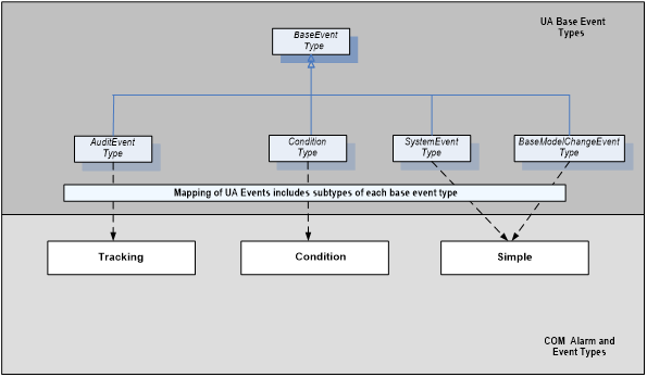
Figure D.2 – Mapping UA Event Types to COM A&E Event Types
Note that the Event type mapping described above also applies to the children of each subtype.
Each A&E Event type (e.g. Simple, Tracking, Condition) has an associated set of Event categories which are intended to define groupings of A&E Events. For example, Level and Deviation are possible Event categories of the Condition Event type for an A&E COM Server. However, since A & C does not explicitly support Event categories, the A&E COM UA Proxy uses A & C Event types to return A&E Event categories to the A&E COM Client. The A&E COM UA Proxy builds the collection of supported categories by traversing the type definitions in the address space of the UA A & C Server. Figure D.3 shows the mapping as follows:
· A&E Tracking categories consist of the set of all Event types defined in the hierarchy of subtypes of AuditEventType and TransitionEventType, including AuditEventType itself and TransitionEventType itself.
· A&E Condition categories consist of the set of all Event types defined in the hierarchy of subtypes of ConditionType, including ConditionType itself.
· A&E Simple categories consist of the set of Event types defined in the hierarchy of subtypes of BaseEventType excluding AuditEventType and ConditionType and their respective subtypes.
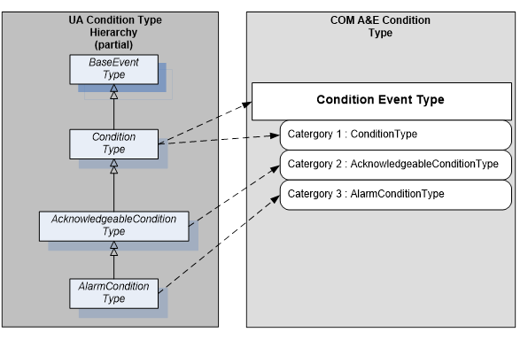
Figure D.3 – Example mapping of UA Event Types to COM A&E categories
Category name is derived from the display name Attribute of the Node type as discovered in the type hierarchy of the UA A & C Server.
Category description is derived from the description Attribute of the Node type as discovered in the type hierarchy of the UA A & C Server.
The A&E COM UA Proxy assigns Category IDs.
D.3.5 Event Category attribute mapping
The collection of Attributes associated with any given A&E Event is encapsulated within the ONEVENTSTRUCT. Therefore, the A&E COM UA Proxy populates the Attribute fields within the ONEVENTSTRUCT using corresponding values from UA Event Notifications either directly (e.g., Source, Time, Severity) or indirectly (e.g., OPC COM Event category determined by way of the UA Event type). Table D.5 lists the Attributes currently defined in the ONEVENTSTRUCT in the leftmost column. The rightmost column of Table D.5 indicates how the A&E COM UA proxy defines that Attribute.
Table D.5 – Event category attribute mapping table
|
A&E ONEVENTSTRUCT “attribute” |
A&E COM UA Proxy Mapping |
|
The following items are present for all A&E event types |
|
|
szSource |
UA BaseEventType Property: SourceName |
|
ftTime |
UA BaseEventType Property: Time |
|
szMessage |
UA BaseEventType Property: Message |
|
dwEventType |
See Clause D.3.3 |
|
dwEventCategory |
See Clause D.3.4 |
|
dwSeverity |
UA BaseEventType Property: Severity |
|
dwNumEventAttrs |
Calculated within A&E COM UA Proxy |
|
pEventAttributes |
Constructed within A&E COM UA Proxy |
|
The following items are present only for A&E Condition-Related Events |
|
|
szConditionName |
UA ConditionType Property: ConditionName |
|
szSubConditionName |
UA ActiveState Property: EffectiveDisplayName |
|
wChangeMask |
Calculated within Alarms and Events COM UA proxy |
|
wNewState: OPC_CONDITION_ACTIVE |
A & C AlarmConditionType Property: ActiveState Note that events mapped as non-Condition Events and those that do not derive from AlarmConditionType are set to ACTIVE by default. |
|
wNewState: OPC_CONDITION_ENABLED |
A & C ConditionType Property: EnabledState Note, Events mapped as non-Condition Events are set to ENABLED (state bit mask = 0x1) by default. |
|
wNewState: OPC_CONDITION_ACKED |
A & C AcknowledgeableConditionType Property: AckedState Note that A & C Events mapped as non-Condition Events or which do not derive from AcknowledgeableConditionType are set to UNACKNOWLEDGED and AckRequired = False by default. |
|
wQuality |
A & C ConditionType Property: Quality Note that Events mapped as non-Condition Events are set to OPC_QUALITY_GOOD by default.
In general, the Severity field of the StatusCode is used to map COM status codes OPC_QUALITY_BAD, OPC_QUALITY_GOOD and OPC_QUALITY_UNCERTAIN. When possible, specific status' are mapped directly. These include (UA => COM):
Bad status codes Bad_ConfigurationError => OPC_QUALITY_CONFIG_ERROR Bad_NotConnected => OPC_QUALITY_NOT_CONNECTED Bad_DeviceFailure => OPC_QUALITY_DEVICE_FAILURE Bad_SensorFailure => OPC_QUALITY_SENSOR_FAILURE Bad_NoCommunication => OPC_QUALITY_COMM_FAILURE Bad_OutOfService => OPC_QUALITY_OUT_OF_SERVICE
Uncertain status codes Uncertain_NoCommunicationLastUsableValue => OPC_QUALITY_LAST_USABLE Uncertain_LastUsableValue => OPC_QUALITY_LAST_USABLE Uncertain_SensorNotAccurate => OPC_QUALITY_SENSOR_CAL Uncertain_EngineeringUnitsExceeded => OPC_QUALITY_EGU_EXCEEDED Uncertain_SubNormal => OPC_QUALITY_SUB_NORMAL
Good status codes Good_LocalOverride => OPC_QUALITY_LOCAL_OVERRIDE |
|
bAckRequired |
If the ACKNOWLEDGED bit (OPC_CONDITION_ACKED) is set then the Ack Required Boolean is set to False, otherwise the Ack Required Boolean is set to True. If the Event is not of type AcknowledgeableConditionType or subtype then the AckRequired Boolean is set to False. |
|
ftActiveTime |
If the Event is of type AlarmConditionType or subtype and a transition from ActiveState of False to ActiveState to True is being processed then the TransitionTime Property of ActiveState is used. If the Event is not of type AlarmConditionType or subtype then this field is set to current time. Note: Additional logic applies to exclusive limit alarms, This value should be mapped to the LimitState.TransitionTime. |
|
dwCookie |
Generated by the A&E COM UA Proxy. These unique Condition Event cookies are not associated with any related identifier from the address space of the UA A & C Server. |
|
The following is used only for A&E tracking events and for A&E condition-relate events which are acknowledgement notifications |
|
|
szActorID |
|
|
Vendor specific Attributes – ALL |
|
|
ACK Comment |
|
|
AREAS |
All A&E Events are assumed to support the "Areas" Attribute. However, no Attribute or Property of an A & C Event is available which provides this value. Therefore, the A&E COM UA Proxy initializes the value of the Areas Attribute based on the MonitoredItem producing the Event. If the A&E COM Client has applied no area filtering to a Subscription, the corresponding A & C Subscription will contain just one MonitoredItem – that of the UA A & C Server Object. Events forwarded to the A&E COM Client on behalf of this Subscription will carry an Areas Attribute value of empty string. If the A&E COM Client has applied an area filter to a Subscription then the related UA A & C Subscription will contain one or more MonitoredItems for each notifier Node identified by the area string(s). Events forwarded to the A&E COM Client on behalf of such a Subscription will carry an areas Attribute whose value is the relative path to the notifier which produced the Event (i.e., the fully qualified area name). |
|
Vendor specific Attributes – based on category |
|
|
SubtypeProperty1 |
All the UA A & C subtype Properties that are not part of the standard set exposed by BaseEventType or ConditionType |
|
SubtypePropertyn |
|
Condition Event instance records are stored locally within the A&E COM UA Proxy. Each record holds ONEVENTSTRUCT data for each EventSource/Condition instance. When the Condition instance transitions to the state INACTIVE|ACKED, where AckRequired = True or simply INACTIVE, where AckRequired = False, the local Condition record is deleted. When a Condition Event is received from the UA A & C Server and a record for this Event (identified by source/Condition pair) already exists in the proxy Condition Event store, the existing record is simply updated to reflect the new state or other change to the Condition, setting the change mask accordingly and producing an OnEvent callback to any subscribing Clients. In the case where the Client application acknowledges an Event which is currently unacknowledged (AckRequired = True), the UA A & C Server Acknowledge Method associated with the Condition is called and the subsequent Event produced by the UA A & C Server indicating the transition to acknowledged will result in an update to the current state of the local Condition record as well as an OnEvent Notification to any subscribing Clients.
The A&E COM UA Proxy maintains the mapping of Attributes on an Event category basis. An Event category inherits its Attributes from the Properties defined on all supertypes in the UA Event Type hierarchy. New Attributes are added for any Properties defined on the direct UA Event type to A&E category mapping. The A&E COM UA Proxy adds two Attributes to each category: AckComment and Areas. Figure D.4 shows an example of this mapping.
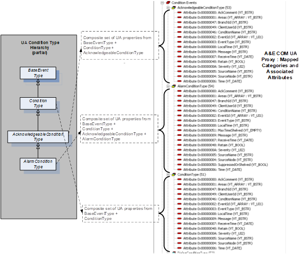
Figure D.4 – Example mapping of UA Event Types to A&E categories with attributes
Events of any subtype of ConditionType are designated COM Condition Events and are subject to additional processing due to the stateful nature of Condition Events. COM Condition Events transition between states composed of the triplet ENABLED|ACTIVE|ACKNOWLEDGED. In UA A & C, Event subtypes of ConditionType only carry a value which can be mapped to ENABLED (DISABLED) and optionally, depending on further sub typing, may carry additional information which can be mapped to ACTIVE (INACTIVE) or ACKNOWLEDGED (UNACKNOWLEDGED). Condition Event processing proceeds as described in Table D.5 (see A&E ONEVENTSTRUCT “Attribute” rows: OPC_CONDITION_ACTIVE, OPC_CONDITION_ENABLED and OPC_CONDITION_ACKED).
A&E COM browsing yields a hierarchy of areas and sources. Areas can contain both sources and other areas in tree fashion where areas are the branches and sources are the leaves. The A&E COM UA Proxy relies on the "HasNotifier" Reference to assemble a hierarchy of branches/areas such that each Object Node which contains a HasNotifier Reference and whose EventNotifier Attribute is set to SubscribeToEvents is considered an area. The root for the HasNotifier hierarchy is the Server Object. Starting at the Server Object, HasNotifier References are followed and each HasNotifier target whose EventNotifier Attribute is set to SubscribeToEvents becomes a nested COM area within the hierarchy.
Note that the HasNotifier target can also be a HasNotifier source. Further, any Node which is a HasEventSource source and whose EventNotifier Attribute is set to SubscribeToEvents is also considered a COM Area. The target Node of any HasEventSource Reference is considered an A&E COM “source” or leaf in the A&E COM browse tree.
In general, Nodes which are the source Nodes of the HasEventSource Reference and/or are the source Nodes of the HasNotifier Reference are always A&ECOM Areas. Nodes which are the target Nodes of the HasEventSource Reference are always A&E COM Sources. Note however that targets of HasEventSource which cannot be found by following the HasNotifier References from the Server Object are ignored.
Given the above logic, the A&E COM UA Proxy browsing will have the following limitations: Only those Nodes in the UA A & C Server’s address space which are connected by the HasNotifier Reference (with exception of those contained within the top level Objects folder) are considered for area designation. Only those Nodes in the UA A & C Server’s address space which are connected by the HasEventSource Reference (with exception of those contained within the top level Objects folder) are considered for area or source designation. To be an area, a Node shall contain a HasNotifier Reference and its EventNotifier Attribute shall be set to SubscribeToEvents. To be a source, a Node shall be the target Node of a HasEventSource Reference and shall have been found by following HasNotifier References from the Server Object.
D.3.8.1 Qualified name syntax
From the root of any sub tree in the address space of the UA A & C Server, the A&E COM Client may request the list of areas and/or sources contained within that level. The resultant list of area names or source names will consist of the set of browse names belonging to those Nodes which meet the criteria for area or source designation as described above. These names are "short" names meaning that they are not fully qualified. The A&E COM Client may request the fully qualified representation of any of the short area or source names. In the case of sources, the fully qualified source name returned to the A&E COM Client will be the string encoded value of the NodeId as defined in 10000-6 (e.g., “ns=10;i=859“). In the case of areas, the fully qualified area name returned to the COM Client will be the relative path to the notifier Node as defined in 10000-4 (e.g., “/6:Boiler1/6:Pipe100X/1:Input/2:Measurement“). Relative path indices refer to the namespace table described below.
D.3.8.2 Namespace table
UA Server Namespace table indices may vary over time. This represents a problem for those A&E COM Clients which cache and reuse fully qualified area names. One solution to this problem would be to use a qualified name syntax which includes the complete URIs for all referenced table indices. This however would result in fully qualified area names which are unwieldy and impractical for use by A&E COM Clients. As an alternative, the A&E COM UA Proxy will maintain an internal copy of the UA A & C Server's namespace table together with the locally cached endpoint description. The A&E COM UA Proxy will evaluate the UA A & C Server’s namespace table at connect time against the cached copy and automatically handle any re-mapping of indices if required. The A&E COM Client can continue to present cached fully qualified area names for filter purposes and the A&E COM UA Proxy will ensure these names continue to reference the same notifier Node even if the Server's namespace table changes over time.
To implement the relative path, the A&E COM UA Proxy maintains a stack of INode interfaces of all the Nodes browsed leading to the current level. When the A&E COM Client calls GetQualifiedAreaName, the A&E COM UA Proxy first validates that the area name provided is a valid area at the current level. Then looping through the stack, the A&E COM UA Proxy builds the relative path. Using the browse name of each Node, the A&E COM UA Proxy constructs the translated name as follows:
QualifiedName translatedName = new QualifiedName(Name,(ushort) ServerMappingTable[NamespaceIndex]) where
Name – the unqualified browse name of the Node
NamespaceIndex – the Server index
the ServerMappingTable provides the Client namespace index that corresponds to the Server index.
A ‘/’ is appended to the translated name and the A&E COM UA Proxy continues to loop through the stack until the relative path is fully constructed.
D.3.9.1 General
The A&E COM UA Proxy supports all of the defined A&E COM filter criteria.
D.3.9.2 Filter by Event, category or severity
These filter types are implemented using simple numeric comparisons. For Event filters, the received Event shall match the Event type(s) specified by the filter. For Category filters, the received Event’s category (as mapped from UA Event type) shall match the category or categories specified by the filter. For severity filters, the received Event severity shall be within the range specified by the Subscription filter.
D.3.9.3 Filter by source
In the case of source filters, the UA A & C Server is free to provide any appropriate, Server-specific value for SourceName. There is no expectation that source Nodes discovered via browsing can be matched to the SourceName Property of the Event returned by the UA A & C Server using string comparisons. Further, the A&E COM Client may receive Events from sources which are not discoverable by following only HasNotifier and/or HasEventSource References. Thus, source filters will only apply if the source string can be matched to the SourceName Property of an Event as received from the target UA A & C Server. Source filter logic will use the pattern matching rules documented in the A&E COM specification, including the use of wildcard characters.
D.3.9.4 Filter by area
The A&E COM UA Proxy implements Area filtering by adjusting the set of MonitoredItems associated with a Subscription. In the simple case where the Client selects no area filter, the A&E COM UA Proxy will create a UA Subscription which contains just one MonitoredItem, the Server Object. In doing so, the A&E COM UA Proxy will receive Events from the entire Server address space – that is, all Areas. The A&E COM Client will discover the areas associated with the UA Server address space by browsing. The A&E COM Client will use GetQualifiedAreaName as usual in order to obtain area strings which can be used as filters. When the A&E COM Client applies one or more of these area strings to the COM Subscription filter, the A&E COM UA Proxy will create MonitoredItems for each notifier Node identified by the area string(s). Recall that the fully qualified area name is in fact the namespace qualified relative path to the associated notifier Node.
The A&E COM UA Proxy calls the TranslateBrowsePathsToNodeIds Service to get the Node ids of the fully qualified area names in the filter. The Node ids are then added as MonitoredItems to the UA Subscription maintained by the A&E COM UA Proxy. The A&E COM UA Proxy also maintains a reference count for each of the areas added, to handle the case of multiple A&E COM Subscription applying the same area filter. When the A&E COM Subscriptions are removed or when the area name is removed from the filter, the ref count on the MonitoredItem corresponding to the area name is decremented. When the ref count goes to zero, the MonitoredItem is removed from the UA Subscription.
As with source filter strings, area filter strings can contain wildcard characters. Area filter strings which contain wildcard characters require more processing by the A&E COM UA Proxy. When the A&E COM Client specifies an area filter string containing wildcard characters, the A&E COM UA Proxy will scan the relative path for path elements that are completely specified. The partial path containing just those segments which are fully specified represents the root of the notifier sub tree of interest. From this sub tree root Node, the A&E COM UA Proxy will collect the list of notifier Nodes below this point. The relative path associated with each of the collected notifier Nodes in the sub tree will be matched against the Client supplied relative path containing the wildcard character. A MonitoredItem is created for each notifier Node in the sub tree whose relative path matches that of the supplied relative path using established pattern matching rules. An area filter string which contains wildcard characters may result in multiple MonitoredItems added to the UA Subscription. By contrast, an area filter string made up of fully specified path segments and no wildcard characters will result in one MonitoredItem added to the UA Subscription. So, the steps involved are:
1) Check if the filter string contains any of these wild card characters, '*', '?', '#', '[', ']', '!', '-'.
2) Scan the string for path elements that are completely specified by retrieving the substring up to the last occurrence of the ‘/’ character.
3) Obtain the NodeId for this path using TranslateBrowsePathsToNodeIds
4) Browse the Node for all notifiers below it.
5) Using the ComUtils.Match() function match the browse names of these notifiers against the Client supplied string containing the wild card character.
6) Add the Node ids of the notifiers that match as MonitoredItems to the UA Subscription.
Annex E – IEC 62682 Mapping
This section provides a description of how the IEC 62682 information model can be mapped to OPC UA. It highlights term differences, concepts and other functionality. IEC 62682 provides additional information about managing and limiting alarms not covered by this specification.
Note: ISA 18.2 is not discussed by this mapping, but IEC 62682 and ISA 18.2 are related and most definitions in ISA 18.2 correspond to the definitions in IEC 62682.
IEC 62682 defines a large number of terms that are covered by the OPC UA model but not used in the text. These IEC 62682 terms are listed below and include a description, mapping or relationship to OPC UA Alarms and Events:
|
IEC 62682 |
OPC UA Mapping / Related Concept |
IEC 62682 Definition |
|
OPC UA Application of |
||
|
absolute alarm |
ExclusiveDeviationAlarmType NonExclusiveDeviationAlarmType |
An alarm generated when the alarm set point is exceeded. |
|
Both OPC UA models expose a set point and process the Alarm as an absolute Alarm requires, the only difference is the interaction between relative states (High, HighHigh...) |
||
|
adaptive alarm |
|
Alarm for which the setpoint is changed by an algorithm (e.g., rate based). |
|
In OPC UA adaptive alarming may be part of a vendor specific alarm application, but it would or could make use of a number of standard Alarm functions described in this specification. OPC UA provides limit, rate of change and deviation alarming. Vendors can easily develop algorithms to adjust any of the limits that are exposed. |
||
|
adjustable alarm / operator-set alarm |
ExclusiveLimitAlarmType NonExclusiveLimitAlarmType |
An alarm for which the set point can be changed manually by the Operator. |
|
Both OPC UA models allow Alarm limits to be writeable and allow for an Operator to change the limit. For all changes to limits an audit event should be generated tracking the change. |
||
|
advanced alarming |
|
A collection of techniques that can help manage annunciations during specific situations. |
|
In OPC UA advanced alarming may be part of a vendor specific alarm application, but it would or could make use of a number of standard Alarm functions described in this specification, such as adaptive setting of a setpoint for deviation Alarm. It might also require the definition of new Alarm sub-types. |
||
|
Annunciation / Alarm Annunciation |
Retain |
A function of the alarm system is to call the attention of the Operator to an alarm. |
|
OPC UA provides an Alarm model that includes concepts such as re-alarming, Alarm silence and Alarm delays, but it is up to the Client application to make use of these features to generate both audible and visual annunciation to the Operator. OPC UA does not provide visual indication but it does provide priority information on which the client can be configured to provide the appropriate visual display. A key concept for alarm display is the concept of Alarm states and a Retain bit (see Annex B for more details). |
||
|
alarm attribute |
Various Alarm Properties |
The setting for an alarm within the process control system. |
|
OPC UA defines a number of Properties that reflect what would be termed alarm attributes in IEC 62682 such as Alarm setpoint which maps to the setpoint property in an ExclusiveDeviationAlarmType. |
||
|
alarm class |
ConditionClass, ConditionSubClass |
A group of alarms with a common set of alarm management requirements (e.g., testing, training, monitoring, and audit requirements). |
|
OPC UA provides ConditionClasses, but also provides other groupings, like ConditionSubClass OPC UA also specifies a number of predefined classes, but it is expected that vendors, other standards group or even end users will define their own extensions to these classes. The OPC concepts allow Alarms to be categorized as needed. |
||
|
alarm Deadband |
ExclusiveDeviationAlarmType NonExclusiveDeviationAlarmType |
A change in signal from the alarm setpoint necessary for the alarm to return to normal. |
|
In OPC UA, an alarm Deadband is optionally provided for all limit based alarms. It provides the same functionality as described in IEC 62682 |
||
|
filtering(alarm) |
Event Subscription |
A function which selects alarm records to be displayed according to a given element of the alarm record. |
|
In OPC UA Alarms are received by a Client according to the specific filter requested by the Client. The filtering can be very robust or very simple according to the needs of the client. It is up to the Client application to generate and provide the appropriate filter to the server. OPC UA’s Alarm model is a subscription based model, not a push model that is configured on a server. The choice of filter is a client’s responsibility. |
||
|
alarm flood |
Alarm diagnostics |
A condition during which the Alarm rate is greater than the Operator can effectively manage - (e.g., more than 10 Alarms per 10 minutes). |
|
OPC UA does not define Alarm flooding but it does provide the capability to collect diagnostics that would allow an engineer to review overall Alarm performance. |
||
|
alarm group |
alarm group |
A set of alarms with common association (e.g., process unit, process area, equipment set, or service). Alarm groups are primarily used for display purposes. |
|
OPC UA allows the definition of Alarm groups and the assignment of Alarms to these groups. In addition. OPC UA allows Alarms to also be part of a category. OPC UA also allows Alarms to be organized as a HasNotifier hierarchy (see clause 6). Groups, categories and hierarchies can be used for filtering or restricting Alarms that are being displayed. |
||
|
alarm history |
historical events |
long term repository for alarm records. |
|
10000-11 describes historical Events. |
||
|
alarm log |
|
short term repository for alarm records. |
|
This part does not specify repositories for Alarms. Alarm logging is a Client function. |
||
|
alarm management alarm system management |
|
collection of processes and practices for determining, documenting, designing, operating, monitoring, and maintaining alarm systems. |
|
OPC UA provides an infrastructure to allow vendors and Operators to provide Alarm management, as such it should be an integral part of an alarm management system. |
||
|
alarm message |
Events |
text string displayed with the alarm indication that provides additional information to the Operator (e.g., Operator action). |
|
OPC UA provides an Event structure that includes many different pieces of information (see 10000-5 for additional details). Clients can subscribe for as much of this information as desired and display this as an Alarm message. All typical fields that would be associated with an Alarm message are available. In addition, OPC UA provides significant additional information. |
||
|
alarm priority |
Priority |
relative importance assigned to an alarm within the alarm system to indicate the urgency of response (e.g., seriousness of consequences and allowable response time) |
|
OPC UA provides a Priority Variable as part of the Alarm Object that provides the same functionality |
||
|
alarm rate |
Alarm diagnostics |
the number of alarm annunciation, per Operator, in a specific time interval. |
|
OPC UA provides diagnostics allowing the collection of Alarm rate information at any level in the system. |
||
|
Record (Alarm) |
Events, Event filtering |
a set of information which documents an alarm state change. |
|
In OPC UA all Alarms are generated as an Event and the Client can select the fields that are to be included in the Events. This selection can be customized for each AlarmConditionType, which allows a customized Alarm record to be generated. |
||
|
alarm setpoint, alarm limit, alarm trip point |
Limit Alarms, Discrete Alarms |
the threshold value of a process variable or discrete state that triggers the alarm indication. |
|
OPC UA supports Alarm limits and setpoints for multiple Alarm types, including limit Alarms and discrete Alarms. |
||
|
Sorting (alarm) |
|
a function which orders alarm records to be displayed according to a given element of alarm record. |
|
OPC UA does not provide Alarm sorting as part of an event subscription. Multiple filtering options are provided, but the Client is required to perform any ordering of Alarms. |
||
|
alarm summary, alarm list |
|
a display that lists alarm annunciations with selected information (e.g., date, time, priority, and alarm type). |
|
In OPC UA Alarm summaries and Alarm lists are Client functionality and are not specified. Extensive filtering capabilities are provided by the Server to allow easier implementation of Alarm summaries or lists by a Client. |
||
|
Alert |
|
An audible and/or visible means of indicating to the Operator an equipment or process condition that can require evaluation when time allows. |
|
Alerts are items that should be attended to, but are not as urgent as Alarms. OPC UA does not differentiate between Alarms and alerts, but it does provide a full range of priorities for Alarms. It is up to the end users to determine what range of priorities are considered an alert vs an Alarm etc. |
||
|
allowable response time |
|
The maximum time between the annunciation of the alarm and when the Operator takes corrective action to avoid the consequence. |
|
OPC UA does not provide any specific fields for allowable response time, but it does track the times at which an Alarm occurs and when any actions are taken on the Alarm. |
||
|
Annunciator |
|
device or group of devices that call attention to changes in process conditions |
|
OPC UA does not define annunciators, this is Client functionality that can be implemented using OPC UA |
||
|
Audit |
|
comprehensive assessment that includes the evaluation of alarm system performance and the effectiveness of the work practices used to administer the alarm system. |
|
OPC UA does provide a number of features that can facilitate an audit, including diagnostics and audit events. Do not confuse OPC Audit Event with the IEC audit concept. |
||
|
bad-measurement alarm |
|
an alarm generated when the signal for a process measurement is outside the expected range (e.g., 3.8 mA for a 4 mA to 20 mA signal). |
|
A bad measurement Alarm is not defined in OPC UA, but limit Alarms are defined and they could be used directly to represent a bad-measurement Alarm. Alternatively, limit Alarms could be further subtyped to allow easier filtering on bad-measurement Alarms if desired. |
||
|
bit-pattern alarm |
Discrete alarm |
an alarm that is generated when a pattern of digital signals matches a predetermined pattern. |
|
In OPC UA a bit pattern Alarm can be mapped to a DiscreteAlarmType. |
||
|
calculated alarm |
|
An alarm generated from a calculated value instead of a direct process measurement. |
|
In OPC UA any of the defined Alarm types can be applied to calculated values or to process values. |
||
|
call-out alarm |
|
alarm that notifies and informs an Operator by means other than, or in addition to, a console display (e.g., pager or telephone) |
|
OPC UA does not specify call-out alarms, since this is client functionality. OPC UA does provide the ability to categorize or group an Alarm such that it could be easily identified as requiring a different type of annunciation. |
||
|
chattering alarm |
OnDelay, OffDelay |
alarm that repeatedly transitions between the alarm state and the normal state in a short period of time. |
|
The OPC UA features of OnDelay and OffDelay can be used to help control chattering Alarms. |
||
|
Classification |
ConditionClasses |
the process of separating alarms into alarm classes based on common requirements (e.g. testing, training, monitoring, and auditing requirements). |
|
OPC defines a number of extensible ConditionClasses that can be used for this purpose. |
||
|
controller-output alarm |
|
alarm generated from the output signal of a control algorithm (e.g., PID controller) instead of a direct process measurement. |
|
OPC UA does not provide an Alarm type for controller-output alarm, but a type could be created or an existing type could be used, depending on the requirements. |
||
|
dynamic alarming |
|
An automatic modification of alarm attributes based on process state or conditions. |
|
OPC UA does not define dynamic alarming behaviour, but it allows programmatic access to limits, set points or other parameters that would be required for a dynamic alarming solution. |
||
|
enforcement |
|
enhanced alarming technique that can verify and restore alarm attributes in the control system to the values in the master alarm database. |
|
OPC UA does not provide enforcement, but it enables enforcement by providing an information model that includes default setting for Alarm types as well as original settings for dynamic Alarms. These features can be used by a Client application to provide enforcement. |
||
|
fleeting alarm |
Suppression, Shelving |
An alarm that transitions between an active alarm state and an inactive alarm state in a short period of time. |
|
OPC UA provides Alarm Suppression and Shelving which an Operator might use to control fleeting Alarms. |
||
|
first-out alarm first-up alarm |
FirstInGroup FirstInGroupFlag |
An alarm determined (i.e., by first-out logic) to be the first, in a multiple-alarm scenario. |
|
OPC UA can support first-up/first-out Alarms as part of the Alarm information model, including definition of the group of Alarms. |
||
|
instrument diagnostic alarm |
InstrumentDiagnosticAlarmType |
An alarm generated by a field device to indicate a fault (e.g., sensor failure). |
|
OPC UA provides support for InstrumentDiagnostic Alarms that can be used to represent a failed sensor or an instrument diagnostic. |
||
|
monitoring |
Alarm Diagnostics |
measurement and reporting of quantitative (objective) aspects of alarm system performance. |
|
OPC UA provides diagnostic collection capabilities that can be used to measure and reports quantitative information related to alarm system performance. |
||
|
nuisance alarm |
Alarm Diagnostics
|
An alarm that annunciates excessively, unnecessarily, or does not return to normal after the Operator response is taken. EXAMPLE: Chattering alarm, fleeting alarm, or stale alarm. |
|
The OPC UA model provides Alarm Diagnostics for tracking the information needed to identify if an Alarm is a nuisance Alarm (i.e. has been in an Alarm state excessively or does not return to normal). |
||
|
plant state plant mode |
StateMachines |
defined set of operational conditions for a process plant. |
|
OPC UA provides an example StateMachine (see Annex F) that can be customized or adapted to provide process information. This StateMachine could also be used to affect alarming. |
||
|
process area |
Event Hierarchies Object References (Part 5) |
physical, geographical or logical grouping of resources determined by the site. |
|
OPC UA provides multiple manners in which an information model can be displayed, this includes grouping objects into process areas or any other desired grouping. This is an inherent part of the OPC UA information model. |
||
|
re-alarming alarm, re-triggering alarm |
ReAlarmTime ReAlarmRepeatCount |
alarm that is automatically re-annunciated to the Operator under certain conditions. |
|
OPC UA supports re-alarming as part of its base AlarmConditionType. |
||
|
recipe-driven alarm |
StateMachines Alarm Limits |
alarm with setpoints that depend on the recipe that is currently being executed. |
|
OPC UA provides support for adjustable Alarm limits. It also provides support for programs and other functionality that could be used to drive recipes. Annex F provides an example of a StateMachine and how it could be used to adjust Alarm settings. |
||
|
Reset |
LatchedState / Reset |
Operator action that unlatches a latched alarm. |
|
OPC UA provides an optional StateMachine to indicate an Alarm is capable of being latched and is in a latched state. It also provides a Reset Method for clearing the latched state. |
||
|
safety related alarm safety alarm |
SafetyConditionClassType |
an alarm that is classified as critical to process safety for the protection of human life or the environment. |
|
OPC UA defines a safety ConditionClass for grouping safety related alarms. |
||
|
stale alarm |
Alarm Diagnostics |
alarm that remains annunciated for an extended period of time (e.g., 24 hours). |
|
OPC UA Alarm Diagnostics can track the length of time an Alarm is active. |
||
|
state-based alarm - mode-based alarms |
StateMachine |
alarm that has attributes modified or is suppressed based on operating states or process conditions. |
|
OPC UA can provide a system state StateMachine to support process, device or system states (see Annex F). With this StateMachine Servers can adjust Alarm attributes or just Suppress or Disable Alarms based on the StateMachine. The StateMachine can be applied at multiple levels in the system. |
||
|
statistical alarm |
StatisticalConditionClassType |
alarm generated based on statistical processing of a process variable or variables. |
|
OPC UA provides an Alarm Condition class that any of the existing AlarmConditionTypes can be assigned to. This allows any Alarm types, such as limit Alarms, to be generated by statistical analysis. |
||
|
Suppress |
SuppressedOrShelved |
Any mechanism to prevent the indication of the alarm to the Operator when the base alarm condition is present (i.e., shelving, suppressed by design, out-of-service). |
|
OPC UA provides a flag SuppressedOrShelved that matches this functionality. |
||
|
suppressed by design |
SuppressedState |
alarm annunciation to the Operator prevented based on plant state or other conditions. |
|
OPC UA provides a SuppressedState that matches this functionality. |
||
|
system diagnostic alarm |
SystemDiagnosticAlarmType |
alarm generated by the control system to indicate a fault within the system hardware, software or components. |
|
OPC UA defines a system diagnostic Alarm that can be used to represent faults with system hardware, software or components. |
||
|
|
Disable/Enable |
|
|
OPC UA supports enable / Disable of Alarms, which was supported in older version of 18.2 and IEC 62682, but these options are no longer supported and used in either 18.2 or IEC 62682. Servers that wish to be compliant to 18.2 and IEC 62682 should not use Disable / Enable methods defined in this specification. |
The following terms in IEC 62682 match the terms/concepts defined in the OPC UA specification and do not need any addition mapping or discussion:
· Acknowledge
· Active
· Alarm
· Alarm OffDelay
· Alarm OnDelay
· Alarm Type
· Deviation Alarm
· Discrepancy Alarm
· Event
· Highly Managed Alarm
· LatchingAlarm
· OutofService
· Rateofchange alarms
· Return to normal
· Shelve
· Silence
· Unacknowledged
E.3 Alarm records & State Indications
OPC UA provides all of the items listed as both required and recommended as part of its alarm definitions, but it is up to the client to subscribe for the information. In OPC UA the Client controls what alarm information is requested and obtained from the Server. The Server does not define visual aspects of the alarm system, but does provide priority information from which the visual aspect can be set on the client side.
OPC UA also supports all of the states described in IEC 62682. This includes tracking the process states, system states and individual alarm states. OPC UA also provides a StateMachine model that can be used in conjunction with an alarm system to alter alarm behaviour based on the state of a system or process. For example, during start-up or shutdown of a process or a system some alarms might be suppressed.
The behaviour of an OPC UA alarm system also mimics that
required by IEC 62682. All behaviour described in IEC 62682 can easily be
mapped to functionality define in OPC UA Alarm & Conditions.
Annex F System State (Informative)
The state of alarms is affected by the state of the process, equipment, system or plant. For example, when a tank is taken out of service, the level alarms associated with the tank would be no longer used, until the tank is returned to service. This section describes a StateMachine that can be deployed as part of a system designed and used to reflect the current state of the system, process, equipment or item. Customized version of this model can be implemented for any system, this sample is just an illustration.
The current state from the StateMachine is applied to all items in the HasNotifier hierarchy below the object with which the StateMachine is associated. The SystemState StateMachine can be used to automatically disable, enable, suppress or un-suppress Alarms related to the Object (with in the hierarchy of alarms from the given object). The StateMachine can also be used by advanced alarming software to adjust the setpoint, limits or other items related to the Alarms in the hierarchy.
Optionally, multiple SystemState StateMachines can be deployed.
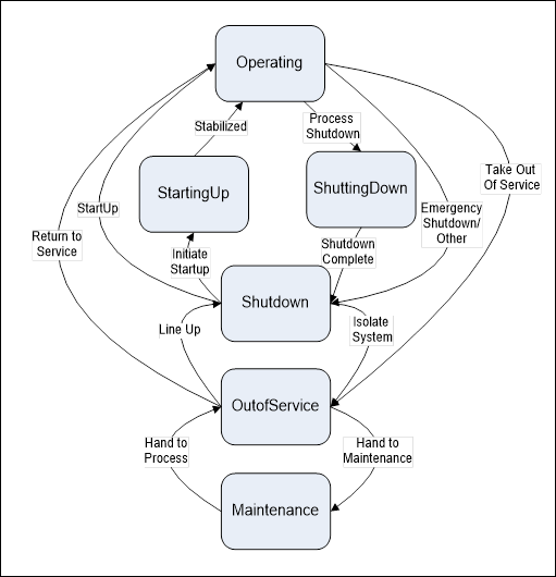
Figure F.1 – SystemState transitions
F.2 SystemStateStateMachineType
The SystemStateStateMachineType includes a hierarchy of sub-states. It supports multiple transitions between Operating, StartingUp, ShuttingDown, Shutdown, OutOfService and Maintenance.
The state machine is illustrated in Figure F.2 and formally defined in Table F.1.
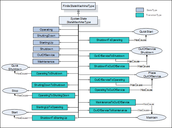
Figure F.2 – SystemStateStateMachineType Model
Table F.1 – SystemStateStateMachineType definition
|
Attribute |
Value |
||||
|
BrowseName |
SystemStateStateMachineType |
||||
|
IsAbstract |
False |
||||
|
References |
Node Class |
BrowseName |
DataType |
TypeDefinition |
Modelling Rule |
|
Subtype of the FiniteStateMachineType defined in 10000-16 |
|||||
|
|
|
|
|
|
|
|
HasComponent |
Object |
Operating |
|
StateType |
|
|
HasComponent |
Object |
ShuttingDown |
|
StateType |
|
|
HasComponent |
Object |
StartingUp |
|
StateType |
|
|
HasComponent |
Object |
Shutdown |
|
StateType |
|
|
HasComponent |
Object |
OutOfService |
|
StateType |
|
|
HasComponent |
Object |
Maintenance |
|
StateType |
|
|
|
|
|
|
|
|
|
HasComponent |
Object |
ShutdownToOperating |
|
TransitionType |
|
|
HasComponent |
Object |
OperatingToShutdown |
|
TransitionType |
|
|
HasComponent |
Object |
ShuttingdownToShutdown |
|
TransitionType |
|
|
HasComponent |
Object |
OperatingToShuttingdown |
|
TransitionType |
|
|
HasComponent |
Object |
StartingUpToOperating |
|
TransitionType |
|
|
HasComponent |
Object |
ShutdownToStartingUp |
|
TransitionType |
|
|
HasComponent |
Object |
OutOfServiceToShutdown |
|
TransitionType |
|
|
HasComponent |
Object |
ShutdownToOutOfService |
|
TransitionType |
|
|
HasComponent |
Object |
OutOfServiceToOperating |
|
TransitionType |
|
|
HasComponent |
Object |
OperatingToOutOfService |
|
TransitionType |
|
|
HasComponent |
Object |
MaintenanceToOutOfService |
|
TransitionType |
|
|
HasComponent |
Object |
OutOfServiceToMaintenance |
|
TransitionType |
|
|
|
|
|
|
|
|
|
HasComponent |
Method |
Start |
Defined in Clause XXX |
Optional |
|
|
HasComponent |
Method |
Maintain |
Defined in Clause XXX |
Optional |
|
|
HasComponent |
Method |
Stop |
Defined in Clause XXX |
Optional |
|
|
HasComponent |
Method |
PlaceOutOfService |
Defined in Clause XXX |
Optional |
|
|
HasComponent |
Method |
QuickShutdown |
Defined in Clause XXX |
Optional |
|
|
HasComponent |
Method |
QuickStart |
Defined in Clause XXX |
Optional |
|
|
HasComponent |
Method |
OutOfServiceShutdown |
Defined in Clause XXX |
Optional |
|
The actual selection of States and Transitions would depend on the deployment of the StateMachine. If the StateMachine were being applied to a tank or other part of a process it might have a different set of States then if it was applied to a meter or instrument. The meter may only have Operating, OutOfService and Maintenance, while the tank may have all of the described States and Transitions. The transitions are defined in Table F.2.
The StateMachine supports six possible states including: Operating, ShuttingDown, StartingUp, Shutdown, OutOfService, Maintenance. It supports 12 possible Transitions and 7 possible Methods.
Table F.2 – SystemStateStateMachineType additional references
|
SourceBrowsePath |
References |
IsForward |
TargetBrowsePath |
|
ShutdownToOperating |
FromState |
True |
Shutdown |
|
|
ToState |
True |
Operating |
|
|
HasCause |
True |
QuickStart |
|
OperatingToShutdown |
FromState |
True |
Operating |
|
|
ToState |
True |
Shutdown |
|
|
HasCause |
True |
QuickShutdown |
|
ShuttingDownToShutdown |
FromState |
True |
ShuttingDown |
|
|
ToState |
True |
Shutdown |
|
OperatingToShuttingDown |
FromState |
True |
Operating |
|
|
ToState |
True |
ShuttingDown |
|
|
HasCause |
True |
Stop |
|
StartingUpToOperating |
FromState |
True |
StartingUp |
|
|
ToState |
True |
Operating |
|
ShutdownToStartingUp |
FromState |
True |
Shutdown |
|
|
ToState |
True |
StartingUp |
|
|
HasCause |
True |
Start |
|
OutOfServiceToShutdown |
FromState |
True |
OutOfService |
|
|
ToState |
True |
Shutdown |
|
|
HasCause |
True |
OutOfServiceShutdown |
|
ShutdownToOutOfService |
FromState |
True |
Shutdown |
|
|
ToState |
True |
OutOfService |
|
|
HasCause |
True |
OutOfServiceShutdown |
|
OutOfServiceToOperating |
FromState |
True |
OutOfService |
|
|
ToState |
True |
Operating |
|
|
HasCause |
True |
PlaceOutOfService |
|
OperatingToOutOfService |
FromState |
True |
Operating |
|
|
ToState |
True |
OutOfService |
|
|
HasCause |
True |
PlaceOutOfService |
|
MaintenanceToOutOfService |
FromState |
True |
Maintenance |
|
|
ToState |
True |
OutOfService |
|
|
HasCause |
True |
Maintain |
|
OutOfServiceToMaintenance |
FromState |
True |
OutOfService |
|
|
ToState |
True |
Maintenance |
|
|
HasCause |
True |
Maintain |
The component Variables of the SystemStateStateMachineType have additional Attributes defined inTable 149.
Table 149 – SystemStateStateMachineType Attribute values for child Nodes
|
BrowsePath |
Value Attribute |
||
|
1 |
||
|
2 |
||
|
3 |
||
|
4 |
||
|
5 |
||
|
6 |
||
|
41 |
||
|
14 |
||
|
24 |
||
|
12 |
||
|
31 |
||
|
42 |
||
|
54 |
||
|
45 |
||
|
51 |
||
|
15 |
||
|
65 |
||
|
56 |
The system can always generate additional HasCause References, such as internal code. No HasEffect References are defined, but an implementation might define HasEffect References (such as HasEffectDisable) for disabling or enabling Alarms, suppressing Alarms or adjusting setpoints or limits of Alarms. The targets of the reference might be an individual Alarm or portion of a plant or piece of equipment. See section 7 for a list of HasEffect References that could be used.
___________